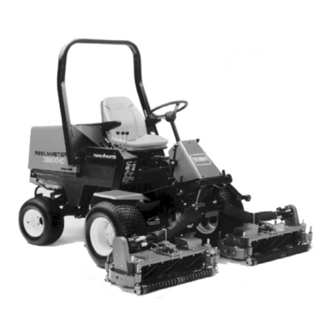
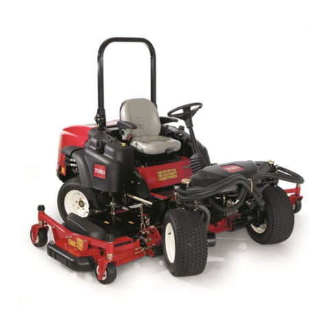
Toro Greensmaster 3150 04358 User manual

FormNo.3398-668RevA
Greensmaster®31502-Wheel
DriveTractionUnit
ModelNo.04358—SerialNo.316000001andUp
Registeratwww.Toro.com.
OriginalInstructions(EN)*3398-668*A

ThisproductcomplieswithallrelevantEuropeandirectives;
fordetails,pleaseseetheseparateproductspecicDeclaration
ofConformity(DOC)sheet.
WARNING
CALIFORNIA
Proposition65Warning
Thisproductcontainsachemicalorchemicals
knowntotheStateofCaliforniatocausecancer,
birthdefects,orreproductiveharm.
Theengineexhaustfromthisproduct
containschemicalsknowntotheStateof
Californiatocausecancer,birthdefects,
orotherreproductiveharm.
ThissparkignitionsystemcomplieswithCanadianICES-002.
ItisaviolationofCaliforniaPublicResourceCode
Section4442or4443touseoroperatetheengineonany
forest-covered,brush-covered,orgrass-coveredlandunless
theengineisequippedwithasparkarrester,asdenedin
Section4442,maintainedineffectiveworkingorderorthe
engineisconstructed,equipped,andmaintainedforthe
preventionofre.
Introduction
Thismachineisaride-on,reel-bladelawnmowerintended
tobeusedbyprofessional,hiredoperatorsincommercial
applications.Itisprimarilydesignedforcuttinggrasson
well-maintainedlawnsinparks,golfcourses,sportselds,
andoncommercialgrounds.Itisnotdesignedforcutting
brush,mowinggrassandothergrowthalongsidehighways,
orforagriculturaluses.
Readthisinformationcarefullytolearnhowtooperateand
maintainyourproductproperlyandtoavoidinjuryand
productdamage.Youareresponsibleforoperatingthe
productproperlyandsafely.
YoumaycontactTorodirectlyatwww.Toro.comforproduct
andaccessoryinformation,helpndingadealer,ortoregister
yourproduct.
Wheneveryouneedservice,genuineToroparts,oradditional
information,contactanAuthorizedServiceDealerorToro
CustomerServiceandhavethemodelandserialnumbersof
yourproductready.Figure1identiesthelocationofthe
modelandserialnumbersontheproduct.Writethenumbers
inthespaceprovided.
Figure1
1.Modelandserialnumberlocation
ModelNo.
SerialNo.
Thismanualidentiespotentialhazardsandhassafety
messagesidentiedbythesafety-alertsymbol(Figure2),
whichsignalsahazardthatmaycauseseriousinjuryordeath
ifyoudonotfollowtherecommendedprecautions.
Figure2
1.Safety-alertsymbol
Thismanualalsouses2wordstohighlightinformation.
Importantcallsattentiontospecialmechanicalinformation
andNoteemphasizesgeneralinformationworthyofspecial
attention.
©2015—TheToro®Company
8111LyndaleAvenueSouth
Bloomington,MN554202
Contactusatwww.Toro.com.
PrintedintheUSA
AllRightsReserved

Contents
Safety...........................................................................4
SafeOperatingPractices...........................................4
ToroMowerSafety..................................................5
SoundPowerLevel..................................................7
SoundPressureLevel...............................................7
VibrationLevel......................................................7
SafetyandInstructionalDecals.................................8
Setup...........................................................................12
1ActivatingandChargingtheBattery........................13
2InstallingtheBattery............................................14
3InstallingtheRollover-ProtectionSystem
(ROPS).............................................................14
4InstallingtheCuttingUnits....................................15
5AddingRearBallastandWeightKit........................16
6InstallingCEDecals.............................................17
7InstallingtheCEGuardKit...................................17
8ReducingtheTirePressure....................................17
9BurnishingtheBrakes...........................................17
ProductOverview.........................................................18
Controls...............................................................18
Specications........................................................20
Attachments/Accessories........................................20
Operation....................................................................21
ThinkSafetyFirst...................................................21
CheckingtheEngineOil..........................................21
FillingtheFuelTank...............................................21
CheckingtheHydraulic-FluidLevel..........................22
CheckingtheTirePressure......................................23
CheckingtheTorqueoftheWheelNuts.....................23
BreakingintheMachine..........................................23
StartingtheEngine.................................................24
CheckingtheSafety-InterlockSystem........................24
CheckingtheLeakDetector.....................................25
SettingtheReelSpeed.............................................26
PreparingtheMachineforMowing...........................26
Mowing................................................................27
InspectingandCleaningafterMowing.......................28
TransportingtheMachine........................................28
LoadingtheMachine..............................................29
TowingtheMachine...............................................29
Maintenance.................................................................30
RecommendedMaintenanceSchedule(s)......................30
DailyMaintenanceChecklist....................................31
ServiceIntervalChart.............................................32
PremaintenanceProcedures........................................32
RemovingtheSeatAssembly....................................32
JackingtheMachine................................................32
Lubrication...............................................................33
GreasingtheMachine.............................................33
EngineMaintenance..................................................35
ServicingtheAirCleaner.........................................35
ChangingtheEngineOilandFilter...........................35
AdjustingtheThrottleLever....................................36
AdjustingtheChokeControl....................................36
AdjustingtheEngineSpeed.....................................37
ReplacingtheSparkPlugs........................................37
FuelSystemMaintenance...........................................38
ReplacingtheFuelFilter..........................................38
InspectingtheFuelLinesandConnections.................38
ElectricalSystemMaintenance....................................38
ServicingtheBattery...............................................38
ServicingtheFuses.................................................39
DriveSystemMaintenance.........................................39
AdjustingtheTransmissionforNeutral.....................39
AdjustingtheTransportSpeed.................................40
AdjustingtheMowingSpeed....................................40
BrakeMaintenance....................................................41
AdjustingtheBrakes...............................................41
ControlsSystemMaintenance.....................................41
AdjustingtheCuttingUnitLift/Drop........................41
AdjustingtheLiftCylinders.....................................42
HydraulicSystemMaintenance....................................42
ChangingtheHydraulicFluidandFilter.....................42
CheckingtheHydraulicLinesandHoses....................43
CuttingUnitMaintenance...........................................43
BacklappingtheCuttingUnits..................................43
Storage........................................................................44
3

Safety
Thismachinehasbeendesignedinaccordancewith
ENISO5395:2013andANSIB71.4-2012andmeets
thesestandardswhen19.5kg(43lb)ofballastandthe
appropriatewheelweightkitareadded.Complianceto
ENISO5395:2013alsorequiresadditionaldecalsanda
guardkitasdescribedin6InstallingCEDecals(page
17)and7InstallingtheCEGuardKit(page17).
Improperuseormaintenancebytheoperatororowner
canresultininjury.Toreducethepotentialforinjury,
complywiththesesafetyinstructionsandalwayspay
attentiontothesafetyalertsymbol(Figure2),which
meansCaution,Warning,orDanger—personalsafety
instruction.Failuretocomplywiththeinstructionmay
resultinpersonalinjuryordeath.
SafeOperatingPractices
Training
•ReadtheOperator'sManualandothertrainingmaterial.If
theoperator(s)ormechanic(s)cannotreadthemanualitis
theowner'sresponsibilitytoexplainthismaterialtothem.
•Becomefamiliarwiththesafeoperationoftheequipment,
operatorcontrols,andsafetysigns.
•Alloperatorsandmechanicsshouldbetrained.The
ownerisresponsiblefortrainingtheusers.
•Neverletchildrenoruntrainedpeopleoperateorservice
theequipment.Localregulationsmayrestricttheageof
theoperator.
•Theowner/usercanpreventandisresponsiblefor
accidentsorinjuriesoccurringtopeopleorproperty.
Preparation
•Evaluatetheterraintodeterminewhataccessoriesand
attachmentsareneededtoproperlyandsafelyperform
thejob.Useonlyaccessoriesandattachmentsapproved
bythemanufacturer.
•Wearappropriateclothingincludingsubstantial,
slip-resistantfootwear,safetyglasses,andhearing
protection.Tiebacklonghair.Donotwearjewelry.
•Inspecttheareawhereyouwillusetheequipmentand
removeallobjectsthatcouldbethrownbythemachine,
suchasrocks,toys,andwire.
•Checkthatoperatorpresencecontrols,safetyswitches,
andshieldsareattachedandfunctioningproperly.Donot
operatethemachineunlesstheyarefunctioningproperly.
Operation
•Donotoperatetheengineinaconnedspacewhere
dangerouscarbonmonoxideandotherexhaustgasses
cancollect.
•Operatethemachineonlyingoodlight,keepingaway
fromholesandhiddenhazards.
•Besurealldrivesareinneutralandparkingbrakeis
engagedbeforestartingengine.Startengineonlyfrom
theoperator'sposition.Useseatbeltsifprovided.
•Slowdownanduseextracareonhillsides.Besureto
travelintherecommendeddirectiononhillsides.Turf
conditionscanaffectthemachine'sstability.Usecaution
whileoperatingneardrop-offs.
•Slowdownandusecautionwhenmakingturnsandwhen
changingdirectionsonslopes.
•Neveroperatewithoutguardssecurelyinplace.Besure
allinterlocksareattached,adjusted,andfunctioning
properly.
•Donotchangetheenginegovernorsettingoroverspeed
theengine.
•Stopthemachineonlevelground,lowerthecuttingunits,
disengagethedrives,engagetheparkingbrake,andshut
offtheenginebeforeleavingtheoperator'spositionfor
anyreason,includingemptyingthegrassbaskets.
•Stopandinspectthemachineafterstrikingobjectsorif
anabnormalvibrationoccurs.Makenecessaryrepairs
beforeresumingoperations.
•Keephandsandfeetawayfromthecuttingunits.
•Lookbehindanddownbeforebackinguptobesureof
aclearpath.
•Nevercarrypassengersandkeeppetsandbystanders
away.
•Slowdownandusecautionwhenmakingturnsand
crossingroadsandsidewalks.Stopthereelsifnot
mowing.
•Donotoperatethemachinewhentired,ill,orunderthe
inuenceofalcoholordrugs.
•Lightningcancausesevereinjuryordeath.Iflightning
isseenorthunderisheardinthearea,donotoperate
themachine;seekshelter.
•Usecarewhenloadingorunloadingthemachineintoa
trailerortruck.
•Usecarewhenapproachingblindcorners,shrubs,trees,
orotherobjectsthatmayobscurevision.
RolloverProtectionSystem(ROPS)-
UseandMaintenance
•TheROPSisanintegralandeffectivesafetydevice.Use
theseatbeltwhenoperatingthemachine.
•Ensurethatyoucanreleasetheseatbeltquicklyinthe
eventofanemergency.
•Checkcarefullyforoverheadclearances(i.e.branches,
doorways,electricalwires)beforedrivingunderany
objectsanddonotcontactthem.
4


•KeeptheROPSinsafeoperatingconditionby
periodicallythoroughlyinspectingfordamageand
keepingallmountingfastenerstight.
•ReplaceadamagedROPS.Donotrepairorrevise.
•DonotremovetheROPS.
•AnyalterationstoaROPSmustbeapprovedbythe
manufacturer.
SafeHandlingofFuels
•Toavoidpersonalinjuryorpropertydamage,use
extremecareinhandlinggasoline.Gasolineisextremely
ammableandthevaporsareexplosive.
•Extinguishallcigarettes,cigars,pipes,andothersources
ofignition.
•Useonlyanapprovedfuelcontainer.
•Neverremovefuelcaporaddfuelwiththeengine
running.
•Allowenginetocoolbeforerefueling.
•Neverrefuelthemachineindoors.
•Neverstorethemachineorfuelcontainerwherethereis
anopename,spark,orpilotlight,suchasonawater
heateroronotherappliances.
•Neverllcontainersinsideavehicleoronatruckor
trailerbedwithaplasticliner.Alwaysplacecontainerson
thegroundawayfromyourvehiclebeforelling.
•Removeequipmentfromthetruckortrailerandrefuelit
ontheground.Ifthisisnotpossible,thenrefuelsuch
equipmentwithaportablecontainerratherthanfroma
fueldispensernozzle.
•Keepthenozzleincontactwiththerimofthefueltank
orcontaineropeningatalltimesuntilfuelingiscomplete.
•Donotuseanozzle-lock-opendevice.
•Ifyouspillfuelonclothing,changeclothingimmediately.
•Neveroverllthefueltank.Replacethefuelcapand
tightenitsecurely.
•Wipeupanyspills.
MaintenanceandStorage
•Parkthemachineonlevelground,disengagethedrives,
lowerthecuttingunits,settheparkingbrake,stopthe
engine,removethekey,anddisconnectsparkplugwire(s).
Waitforallmovementtostopbeforeadjusting,cleaning,
orrepairingthemachine.
•Cleangrassanddebrisfromcuttingunits,drives,mufers,
andtheenginetohelppreventres.Cleanupoilorfuel
spills.
•Lettheenginecoolbeforestoringanddonotstorethe
machinenearames.
•Shutoffthefuelwhilestoringortransportingthe
machine.Donotstorefuelnearamesordrainthefuel
tankindoors.
•Neverallowuntrainedpersonneltoservicethemachine.
•Usejackstandstosupportcomponentswhenrequired.
•Carefullyreleasepressurefromcomponentswithstored
energy.
•Disconnectthebatteryandremovethesparkplugwire(s)
beforemakinganyrepairs.Disconnectthenegative
terminalrstandthepositivelast.Connectthepositive
terminalrstandthenegativeterminallast.
•Usecareandweargloveswhencheckingthereels.
•Keephandsandfeetawayfrommovingparts.Ifpossible,
donotmakeadjustmentswiththeenginerunning.
•Chargebatteriesinanopen,well-ventilatedarea,away
fromsparkandames.Unplugthechargerbefore
connectingordisconnectingitfromthebattery.Wear
protectiveclothinganduseinsulatedtools.
•Keepallpartsingoodworkingconditionandallhardware
andhydraulicttingstightened.Replaceallwornor
damageddecals.
Hauling
•Usecarewhenloadingorunloadingthemachineintoa
trailerortruck.
•Usefullwidthrampsforloadingmachineintotraileror
truck.
•Tiethemachinedownsecurelyusingstraps,chains,cable,
orropes.Bothfrontandrearstrapsshouldbedirected
downandoutwardfromthemachine.
ToroMowerSafety
ThefollowinglistcontainssafetyinformationspecictoToro
productsorothersafetyinformationthatyoumustknowthat
isnotincludedintheANSIstandards.
Thisproductiscapableofamputatinghandsandfeetand
ofthrowingobjects.Alwaysfollowallsafetyinstructionsto
avoidseriousinjuryordeath.
Useofthisproductforpurposesotherthanitsintendeduse
couldprovedangeroustouserandbystanders.
Operation
•Knowhowtostoptheenginequickly.
•Checkthesafetyinterlockswitchesdailyforproper
operation.
•Beforeattemptingtostarttheengine,disengageallblade
attachmentclutches,shiftintoneutral,andengagethe
parkingbrake.
•Usingthemachinedemandsattention.Topreventloss
ofcontrol:
–Donotdriveclosetosandtraps,ditches,creeks,or
otherhazards.
–Reducespeedwhenmakingsharpturns.Avoid
suddenstopsandstarts.
–Thismachineisnotdesignedorequippedforon-road
useandisa“slow-movingvehicle.”Ifyoumustcross
5

ortravelonapublicroad,youshouldbeawareofand
complywithlocalregulations,suchasrequiredlights,
slow-movingvehiclesigns,andreectors.
–Watchoutfortrafcwhennearorcrossingroads.
Alwaysyieldtheright-of-way.
–Applytheservicebrakeswhengoingdownhillto
keepforwardspeedslowandtomaintaincontrolof
themachine.
•Thegrassbasketsmustbeinplaceduringoperation
ofthereelsorthatchersformaximumsafety.Shutthe
engineoffbeforeemptyingthebaskets.
•Raisethecuttingunitswhendrivingfromoneworkarea
toanother.
•Donottouchtheengine,mufer,orexhaustpipewhile
theengineisrunningorsoonafterithasstoppedbecause
theseareascouldbehotenoughtocauseburns.
•Stayclearoftherotatingscreenatthesideoftheengine
topreventdirectcontactwithyourbodyorclothing.
•Ifacuttingunitstrikesasolidobjectorvibrates
abnormally,stopimmediately,turntheengineoff,waitfor
allmotiontostop,andinspectthemachinefordamage.
Repairorreplaceadamagedreelorbedknifebefore
continuingoperation.
•Beforegettingofftheseat,movethefunctionalcontrol
levertoNEUTRAL,raisethecuttingunits,andwaitforthe
reelstostopspinning.Settheparkingbrake.Stopthe
engineandremovethekeyfromtheignitionswitch.
•Traverseslopescarefully.Donotstartorstopsuddenly
whentravelinguphillordownhill.
•Theoperatormustbeskilledandtrainedinhowtodrive
onhillsides.Failuretousecautiononslopesorhillsmay
causelossofcontrolandcausethemachinetotiporroll,
possiblyresultinginpersonalinjuryordeath.
•Iftheenginestallsorlosesheadwayandcannotmakeit
tothetopofaslope,donotturnthemachinearound.
Alwaysbackslowly,straightdowntheslope.
•Whenapersonoranimalappearsunexpectedlyinor
nearthemowingarea,stopmowing.Carelessoperation,
combinedwithterrainangles,ricochets,orimproperly
positionedguardscanleadtothrown-objectinjuries.Do
notresumemowinguntiltheareaiscleared.
MaintenanceandStorage
•Ensurethatallhydrauliclineconnectorsaretightandthat
allhydraulichosesandlinesareingoodconditionbefore
applyingpressuretothesystem.
•Keepyourbodyandhandsawayfrompin-holeleaksor
nozzlesthatejecthydraulicuidunderhighpressure.
Usepaperorcardboard,notyourhands,tosearchfor
leaks.Hydraulicuidescapingunderpressurecanhave
sufcientforcetopenetratetheskinandcauseserious
injury.
•Beforedisconnectingorperforminganyworkonthe
hydraulicsystem,allpressureinthesystemmustbe
relievedbystoppingtheengineandloweringthecutting
unitsandattachmentstotheground.
•Checkallfuellinesfortightnessandwearonaregular
basis.Tightenorrepairthemasneeded.
•Iftheenginemustberunningtoperformamaintenance
adjustment,keephands,feet,clothing,andanypartsof
thebodyawayfromthecuttingunits,attachments,and
anymovingparts,especiallythescreenatthesideofthe
engine.Keepeveryoneaway.
•Donotoverspeedtheenginebychanginggovernor
settings.Toensuresafetyandaccuracy,havean
AuthorizedToroDistributorcheckthemaximumengine
speedwithatachometer..
•Theenginemustbeshutoffbeforecheckingtheoilor
addingoiltothecrankcase.
•Ifmajorrepairsareeverneededorifassistanceisdesired,
contactanAuthorizedToroDistributor.
•Toensureoptimumperformanceandcontinuedsafety
certicationofthemachine,useonlygenuineToro
replacementpartsandaccessories.Replacementparts
andaccessoriesmadebyothermanufacturerscouldbe
dangerous,andsuchusecouldvoidtheproductwarranty.
6

SoundPowerLevel
Thisunithasaguaranteedsoundpowerlevelof95dBA,
whichincludesanUncertaintyValue(K)of1dBA.
Soundpowerlevelwasdeterminedaccordingtothe
proceduresoutlinedinISO11094.
SoundPressureLevel
Thisunithasasoundpressurelevelattheoperator’searof82
dBA,whichincludesanUncertaintyValue(K)of1dBA.
Soundpressurelevelwasdeterminedaccordingtothe
proceduresoutlinedinENISO5395:2013.
VibrationLevel
Hand-Arm
Measuredvibrationlevelforrighthand=0.97m/s2
Measuredvibrationlevelforlefthand=1.11m/s2
UncertaintyValue(K)=0.5m/s2
Measuredvaluesweredeterminedaccordingtotheprocedures
outlinedinENISO5395:2013.
WholeBody
Measuredvibrationlevel=0.40m/s2
UncertaintyValue(K)=0.5m/s2
Measuredvaluesweredeterminedaccordingtotheprocedures
outlinedinENISO5395:2013.
7

SafetyandInstructionalDecals
Safetydecalsandinstructionsareeasilyvisibletotheoperatorandarelocatednearanyareaofpotential
danger.Replaceanydecalthatisdamagedorlost.
121–9566
000000
000000
000000
000000
000000
000000
000000
000000
000
000
00
00
00
00
000
000
000
000
000
000
000
000
000
000
000
000
000
000
000
000
0000000000
0000000000
0000000000
0000000000
0000000000
0000000000
0000000000
0000000000
0000000000
0000000000
0000000000
0000000000
0000000000
0000000000
0000000000
0000000000
0000000000
0000000000
0000000000
0000000000
0000000000
0000000000
0000000000
0000000000
0000000000
0000000000
0000000000
0000000000
0000000000
0000000000
0000000000
0000000000
0000000000
0000000000
0000000000
000000
000000
000000
000000
000000
000000
000000
000000
000000
000000
000000
000
000
000
000
000
131–2007
1.ReadtheOperator’sManual.7.Continuousvariablesetting
2.Failure/malfunction(Leakdetectoralarmtest)8.Fast
3.Off9.Frontandrearlights
4.Choke10.Off
5.On11.Frontlights
6.Slow
93-6686
1.Hydraulicuid
2.ReadtheOperator'sManual.
117–2718
8

93–9051
1.ReadtheOperator'sManual.
105–8306
1.Forwardmachinespeeds3.Slow-useformowing
2.Fast-usefortransport4.Neutral-usefor
backlapping.
93-8062
1.Tolocktheparkingbrake,
pressthebrakepedaland
theparkingbrakelock.
3.Parkingbrakelock
2.Tounlocktheparking
brake,pressthebrake
pedal.
133-2338
1.Warning—readthe
Operator’sManual,do
notoperatethismachine
unlessyouaretrained.
4.Tippinghazard—slow
machinebeforeturning,
donotturnathighspeeds.
2.Warning—wearhearing
protection.
5.Thrownobject
hazard—keepbystanders
asafedistancefromthe
machine.
3.Cutting/dismemberment
hazardofhandorfoot,
mowerblade—stayaway
frommovingparts;keep
allguardsandshieldsin
place.
6.Warning—locktheparking
brake,stoptheengine
andremovetheignition
keybeforeleavingthe
machine.
9

133-2339
1.Warning—readthe
Operator’sManual,do
notoperatethismachine
unlessyouaretrained.
4.Tippinghazard—donot
driveacrossordown
slopesgreaterthan15
degrees.
2.Warning—wearhearing
protection.
5.Thrownobject
hazard—keepbystanders
asafedistancefromthe
machine.
3.Cutting/dismemberment
hazardofhandorfoot,
mowerblade—stayaway
frommovingparts;keep
allguardsandshieldsin
place.
6.Warning—locktheparking
brake,stoptheengine
andremovetheignition
keybeforeleavingthe
machine.
104–7729
1.Warning—readthe
instructionsbefore
servicingorperforming
maintenance.
2.Cutting/dismemberment
hazard;handorfoot—stop
theengineandwaitfor
movingpartstostop.
BatterySymbols
Someorallofthesesymbolsareonyourbattery.
1.Explosionhazard6.Keepbystandersasafe
distancefromthebattery.
2.Nore,opename,or
smoking.
7.Weareyeprotection;
explosivegasescan
causeblindnessandother
injuries
3.Causticliquid/chemical
burnhazard
8.Batteryacidcancause
blindnessorsevereburns.
4.Weareyeprotection9.Flusheyesimmediately
withwaterandgetmedical
helpfast.
5.ReadtheOperator's
Manual.
10.Containslead;donot
discard.
115-8156
1.Reelheight3.8Bladecuttingunit5.14Bladecuttingunit7.Fast
2.5Bladecuttingunit4.11Bladecuttingunit6.Reelspeed8.Slow
10

105–8305
1.Lowerandengagethe
reels.
4.On
2.Raiseanddisengagethe
reels.
5.Engine—start
3.Engine—stop
115-8226
1.Tippinghazard—readtheOperator'smanual;alwayswear
aseatbeltwhenoperating,donotremovetherollover
protectionsystem(ROPS).
11

Setup
LooseParts
Usethechartbelowtoverifythatallpartshavebeenshipped.
ProcedureDescriptionQty.Use
1Nopartsrequired–Activateandchargethebattery.
Carriagebolt(5/16x3/4inch)2
2Nut(5/16inch)2Installthebattery.
Bolt(1/2x1.75inches)2
Bolt(1/2x1.5inches)6
Washer1
3Nut(1/2inch)8
Installtherolloverprotectionsystem
(ROPS).
Bolt(#10x5/8inch)1
Jamnut(#10)1
Cuttingunit3
4Grassbasket3
Installthecuttingunits.
RearWeightKit,PartNo.100-6441
(purchaseseparately)1
19.5kg(43lb)ofcalciumchloride
(purchaseseparately)1
5RearWeightKit,PartNo.99-1645
(purchaseseparatelyifyouhavea
3-WheelDriveKitinstalled)
1
Addtherearballastandweightkit.
Warningdecal(PartNo.133-2339)1
6Productionyeardecal1InstallEUdecals,ifrequired.
7CEGuardKit,Model04440(purchase
separately)1InstalltheCEguardkit,ifrequired.
8Nopartsrequired–Reducethetirepressure.
9Nopartsrequired–Burnishthebrakes.
MediaandAdditionalParts
DescriptionQty.Use
Operator’sManual1
Engineowner’smanual1
Operatortrainingmaterial1
Readthisinformationbeforeoperatingthemachine.
PartsCatalog1Identifyandorderserviceparts.
Pre-deliveryInspectionSheet1
Noiseratingcerticate1
CerticateofQuality1
DeclarationofConformity1
Emissionswarranty1
Readthiscomplianceinformation.
Ignitionkeys2Startthemachine.
12

1
ActivatingandChargingthe
Battery
NoPartsRequired
Procedure
Useonlyelectrolyte(1.265specicgravity)tollbattery
initially.
WARNING
CALIFORNIA
Proposition65Warning
Batteryposts,terminals,andrelated
accessoriescontainleadandleadcompounds,
chemicalsknowntotheStateofCalifornia
tocausecancerandreproductiveharm.
Washhandsafterhandling.
1.Removethewingnuts,washers,andbatteryclampand
liftoutthebattery.
Important:Donotaddelectrolytewhilethe
batteryisinthemachine.Youcouldspillit,
causingcorrosion.
2.Cleanthetopofthebatteryandremovetheventcaps
(Figure3).
Figure3
3.Carefullylleachcellwithelectrolyteuntiltheplates
arecoveredwithabout6mm(1/4inch)ofuid(Figure
4).
Figure4
1.Electrolyte
4.Allowapproximately20to30minutesforthe
electrolytetosoakintotheplates.Fillasnecessaryto
bringtheelectrolytetowithinabout6mm(1/4inch)
ofthebottomofthellwell(Figure4).
5.Connecta2to4Abatterychargertothebatteryposts.
Chargethebatteryforatleast2hoursat4Aorforat
least4hoursat2Auntilthespecicgravityis1.250
orhigherandthetemperatureisatleast16°C(60°F)
withallcellsgassingfreely.
WARNING
Chargingthebatteryproducesgassesthatcan
explode.
Neversmokenearthebatteryandkeepsparks
andamesawayfromthebattery.
Important:Ifyoudonotchargethebatteryforat
leastthetimespeciedabove,youmayreducethe
lifeofthebattery.
6.Whenthebatteryischarged,disconnectthecharger
fromtheelectricaloutletandbatteryposts.
Note:Afterthebatteryhasbeenactivated,add
onlydistilledwatertoreplacenormalloss,although
maintenance-freebatteriesshouldnotrequirewater
undernormaloperatingconditions.
WARNING
Batteryterminalsormetaltoolscouldshort
againstmetaltractorcomponents,causing
sparks.Sparkscancausethebatterygassesto
explode,resultinginpersonalinjury.
•Whenremovingorinstallingthebattery,
donotallowthebatteryterminalstotouch
anymetalpartsofthetractor.
•Donotallowmetaltoolstoshortbetween
thebatteryterminalsandmetalpartsof
thetractor.
13

Important:Failuretocorrectlyactivatethe
batterymayresultinbatterygassingand/or
prematurebatteryfailure.
7.Installtheventcaps.
2
InstallingtheBattery
Partsneededforthisprocedure:
2Carriagebolt(5/16x3/4inch)
2Nut(5/16inch)
Procedure
1.Mountthebatterywiththebatteryterminalstoward
thefrontofthemachine.
2.Connectthepositivebatterycable(red)fromthe
startersolenoidtothepositivepost(+)ofthebattery
(Figure5).Secureitwithacarriageboltandnut.Make
surethatthecablewillcleartheseat,intherear-most
position,whichcouldcausewearordamagetothe
cable.
WARNING
Batteryterminalsormetaltoolscouldshort
againstmetaltractorcomponentscausing
sparks.Sparkscancausethebatterygassesto
explode,resultinginpersonalinjury.
•Whenremovingorinstallingthebattery,
donotallowthebatteryterminalstotouch
anymetalpartsofthetractor.
•Donotallowmetaltoolstoshortbetween
thebatteryterminalsandmetalpartsof
thetractor.
Figure5
1.Negative(-)3.Batteryclamp
2.Positive(+)4.Wingnut
3.Connecttheblackgroundcable(fromtheenginebase)
tothenegative(-)postofthebattery.Secureitwitha
carriageboltandnut.
WARNING
Incorrectbatterycableroutingcoulddamage
thetractorandcablescausingsparks.Sparks
cancausethebatterygassestoexplode,
resultinginpersonalinjury.
•Alwaysdisconnectthenegative(black)
batterycablebeforedisconnectingthe
positive(red)cable.
•Alwaysconnectthepositive(red)battery
cablebeforeconnectingthenegative
(black)cable.
4.Coatbothterminalswithpetroleumjelly.
5.Installthebatteryclampandwashersandsecurethem
withwingnuts(Figure5).
6.Placetheterminalcoveroverthepositive(+)battery
post.
14

3
Installingthe
Rollover-ProtectionSystem
(ROPS)
Partsneededforthisprocedure:
2Bolt(1/2x1.75inches)
6Bolt(1/2x1.5inches)
1Washer
8Nut(1/2inch)
Procedure
1.Removethescrews,nuts,andwashersupportingthe
jackpadontherightsideofthemachine.
2.Lowertherollbar(Figure6)ontothemounting
brackets,aligningthemountingholes.
3.Securetheleftsideoftherollbartothemounting
bracketwith4bolts(1/2x1.5inch)andlocknuts
(Figure6).
Note:Torquethefastenersto91to115N∙m(67to
85ft-lb).
4.Securetherightsideoftherollbarandthepreviously
removedjackpadtothemountingbracketwith2bolts
(1/2x1.5inches),2bolts(1/2x1.75inches),1washer,
andlocknutsasillustratedinFigure6.
Important:Ensurethatyouinstallthewasherin
thecorrectlocationasillustratedinFigure6.
Note:Torquethefastenersto91to115N∙m(67to
85ft-lb).
WARNING
Failuretoweartheseatbeltwhileoperatingthe
vehiclecanresultinyoubeingthrownfromtheseat
andcrushedduringarolloveraccident.
Alwaysusetheseatbelt.
Figure6
1.Jackpad4.Washer
2.Bolt(1/2x1.75inch)5.Rollbar
3.Bolt(1/2x1.5inch)6.Seatbelt
4
InstallingtheCuttingUnits
ForModels04610,04611,04616,04618,
04619,04624,04652,04654,and04656
Partsneededforthisprocedure:
1Bolt(#10x5/8inch)
1Jamnut(#10)
3Cuttingunit
3Grassbasket
Procedure
Important:Donotraisethesuspensiontothetransport
positionwhenthereelmotorsareintheholdersonthe
machineframe.Damagetothemotorsorhosescould
result.
Note:Whensharpening,settingtheheightofcutor
performingothermaintenanceproceduresonthecutting
units,storethecuttingunitreelmotorsinthesupporttubes
onthefrontoftheframeandsideofthemachinetoprevent
damagingthehoses.
15

1.Removethecuttingunitsfromthecartons.Assemble
andadjustthemaslistedinthecuttingunitOperator's
Manual.
2.Slidethecuttingunitunderthepullframewhilesliding
thelifthookontotheliftarm(Figure7).
Figure7
1.Liftarm2.Lifthook
3.Slidethesleevebackontheballjointreceiverandhook
thereceiverontothecuttingunitballstud.Releasethe
sleevesoitslidesoverthestudandlockstheassemblies
together(Figure8).
G020794
Figure8
1.Pullframe3.Ballstud
2.Pullarm
4.Mountthebasketsonthepullframes,loosenthe
jamnutsonthepullarms,andadjusttheballsockets
untilthereis6to13mm(1/4to1/2inch)clearance
betweenthelipofthebasketandthereelblades.
Note:Thispreventsthebasketfromtippingthe
cuttingunitforward,causingtheliftrollertocomeoff
oftheliftarmwhileinthemowingoperation.
Ensurethatthebasketlipisequidistantfromthereel
bladesallacrosseachreel.Ifthebasketistoocloseto
thereel,itispossibleforthereeltocontactthebasket
whenthecuttingunitisraisedofforloweredtothe
ground.
5.Alignthesocketsintheballjointssotheopensideof
thesocketiscenteredtowardtheballstud,andtighten
thejamnutstosecurethesocketsinposition(Figure9).
G020795
Figure9
1.Pullarm3.Balljoint
2.Jamnut
6.Ensurethatthereisapproximately13mm(1/2inch)
ofthreadsexposedoneachreeldrivemotormounting
bolt(Figure10).
Figure10
1.Drivemotor2.Mountingbolts
7.Coatthesplineshaftofthemotorwithcleangrease.
8.Installthemotorbyrotatingthemotorclockwiseso
thatthemotorangesclearthestuds,thenrotatethe
motorcounterclockwiseuntiltheangesareencircling
thestuds.
9.Tightenthemountingbolts(Figure10).
16

5
AddingRearBallastand
WeightKit
Partsneededforthisprocedure:
1RearWeightKit,PartNo.100-6441(purchase
separately)
119.5kg(43lb)ofcalciumchloride(purchase
separately)
1RearWeightKit,PartNo.99-1645(purchase
separatelyifyouhavea3-WheelDriveKitinstalled)
Procedure
ThisunitcomplieswiththeANSIB71.4-2012andENISO
5395:2013Standardswhenyouequipitwithrearweightkit
100-6441andadd19.5kg(43lb)ofcalciumchlorideballast
totherearwheel.Ifyouinstalla3-WheelDriveKit,useRear
WeightKit,partno.99-1645,insteadofpartno.100-6441.
Important:Ifapunctureoccursinatirewithcalcium
chloride,removetheunitfromtheturfareaasquickly
aspossible.Topreventpossibledamagetotheturf,
immediatelysoaktheaffectedareawithwater.
6
InstallingCEDecals
EUOnly
Partsneededforthisprocedure:
1Warningdecal(PartNo.133-2339)
1Productionyeardecal
Procedure
IfthismachinewillbeusedintheEU,afxthewarning
decal(PartNo.133-2339)overthewarningdecal(PartNo.
133-2338).Applytheproductionyeardecalnexttothe
regulatorydecal.
7
InstallingtheCEGuardKit
EUOnly
Partsneededforthisprocedure:
1CEGuardKit,Model04440(purchaseseparately)
Procedure
ThisunitcomplieswiththeENISO5395:2013Standard
whenyouequipitwiththeCEGuardKit(Model04440).
8
ReducingtheTirePressure
NoPartsRequired
Procedure
Thetiresareover-inatedatthefactoryforshipping
purposes.Reducethepressuretotheproperlevelsbefore
startingthemachine.RefertoCheckingtheTirePressure
(page23).
9
BurnishingtheBrakes
NoPartsRequired
Procedure
Firmlyapplythebrakesanddrivethemachineatmowing
speeduntilthebrakesarehot,asindicatedbytheirsmell.
Youmayneedtoadjustthebrakesafterbreak-in;referto
AdjustingtheBrakes(page41).
17

ProductOverview
Controls
BrakePedal
Pressthebrakepedal(Figure11)tostopthemachineby
actuatingthedrum-typebrakelocatedateachtractionwheel.
ParkingBrakeTab
Tosettheparkingbrake,pressthebrakepedal,thenpressthe
parking-braketab(Figure11)tolockthebrakes.Disengage
thetabbypressingthebrakepedal.Locktheparkingbrake
beforeyouleavethemachine.
Figure11
1.Tractionpedal3.Parking-braketab
2.Brakepedal
TractionPedal
Thetractionpedal(Figure11)has3functions:tomakethe
machinemoveforward,tomoveitbackward,andtostopthe
machine.Pressthetopofthepedaltomoveforwardandthe
bottomofthepedaltomovebackwardortoassistinstopping
whenmovingforward.Also,allowthepedaltomovetothe
NEUTRALpositiontostopthemachine.Donotresttheheel
ofyourfootonreversewhenoperatingforward(Figure12).
Figure12
ThrottleLever
Thethrottlelever(Figure13)givestheoperatortheabilityto
controlthespeedoftheengine.Movingthethrottlelever
towardtheFASTpositionincreasestheenginespeed;moving
thethrottlelevertowardtheSLOWpositionwilldecreasethe
enginespeed,butwillnotstoptheengine.
Figure13
1.Throttlelever4.Leak-detectortestswitch
2.Chokecontrol5.Hourmeter
3.Light-switchposition
Choke
Tostartacoldengine,closethecarburetorchokebymoving
thechokecontrol(Figure13)forwardtotheCLOSED
position.Aftertheenginestarts,regulatethechoketokeep
theenginerunningsmoothly.Assoonaspossible,openthe
chokebypullingitrearwardtotheOPENposition.Awarm
enginerequireslittleornochoking.
Leak-DetectorTestSwitch
Usetheswitch(Figure13)tochecktheoperationoftheleak
detectoralarmandtimedelay.
HourMeter
Thehourmeter(locatedontheleftcontrolpanel)indicates
thetotalhoursthemachinehasoperated.Itstartstofunction
wheneverthekeyswitchisrotatedtoOn.
18

Seat-AdjustmentLever
Thislever,ontheleftsideoftheseat(Figure14),allowsa10
cm(4inch)forwardandrearwardadjustmentoftheseat.
Figure14
1.Seat-adjustmentlever
Raise/LowerMowControl
Movingthecontrol(Figure15)forwardduringoperation
lowersthecuttingunitsandstartsthereels.Pullbackthe
controltostopthereelsandraisethecuttingunits.During
operationpullbackonthecontrolmomentarilyandreleaseit,
ifyouneedtostopthereels;startthereelsagainbymoving
thecontrolforward.
Figure15
1.Functional-controllever3.Raise/lowermowcontrol
2.Ignitionswitch
Functional-ControlLever
Thefunctional-controllever(Figure15)providestwotraction
selectionsplusaNEUTRALposition.Youcanshiftfrommow
totransportortransporttomow(nottoneutral)whilethe
machineisinmotion;nodamagewillresult.
•REARposition—neutralandbacklapping
•MIDDLEposition—usedformowingoperation
•FRONTposition—usedfortransportoperation
IgnitionSwitch
Insertthekeyintotheignitionswitch(Figure15)andturnit
clockwiseasfaraspossibletotheSTARTpositiontostartthe
engine.Releasethekeyassoonastheenginestarts;thekey
willmovetotheONposition.Turnthekeycounterclockwise
totheOFFpositiontostoptheengine.
Steering-WheelLockingLever
Rotatethelever(Figure16)forwardtoloosentheadjustment,
raiseorlowersteeringwheelforoperatorcomfort,then,
rotatetheleverrearwardtotightentheadjustment.
Figure16
1.Steering-wheellockinglever
Steering-ArmLockingKnob
Loosentheknob(Figure17)untiltheshoulderontheknob
clearsthenotchesinthesteeringarm.Raiseorlowerthe
steeringarmtothedesiredheightwhilealigningtheshoulder
oftheknobwiththenotchinthesteeringarm.Tightenthe
knobtolocktheadjustment.
Figure17
1.Steering-armlockingknob
19

Fuel-ShutoffValve
Closethefuel-shutoffvalve(Figure18),underthefueltank,
whenstoringortransportingthemachineonatruckortrailer.
Figure18
1.Fuel-shutoff(underthefueltank)
BacklapLever
Usethebacklaplever(Figure19)inconjunctionwiththe
lowermow/raisecontrolleverforbacklappingthereels.
Figure19
1.Backlaplever2.Reel-speedcontrol
Reel-SpeedControl
Usethereel-speedcontrol(Figure19)toadjustthespeedof
thereels.
Specications
Note:Specicationsanddesignaresubjecttochange
withoutnotice.
OverallWidth(w/reels)177cm(69-3/4inches)
OverallLength229cm(90inches)
OverallHeight189cm(74-1/2inches)
OverallWeightw/11-blade
cuttingunits
583kg(1,374lb)
NetWeight(dry)493kg(1,087lb)
WidthofCut150cm(59inches)
WheelTread126cm(49-1/2inches)
WheelBase119cm(46-7/8inches)
MowSpeed(adjustable)3to8km/h(2to5mph)
approximately
TransportSpeed13km/h(8.0mph)
approximately
ReverseSpeed4km/h(2.5mph)
ReelSpeed(at2,850rpm
enginespeed)
1,845rpmapproximately
Attachments/Accessories
AselectionofToroapprovedattachmentsandaccessoriesis
availableforusewiththemachinetoenhanceandexpand
itscapabilities.ContactyourAuthorizedServiceDealeror
Distributororgotowww .Toro.comforalistofallapproved
attachmentsandaccessories.
Tobestprotectyourinvestmentandmaintainoptimal
performanceofyourToroequipment,countonTorogenuine
parts.Whenitcomestoreliability,Torodeliversreplacement
partsdesignedtotheexactengineeringspecicationofour
equipment.Forpeaceofmind,insistonTorogenuineparts.
20
Table of contents
Other Toro Lawn Mower manuals

Toro
Toro e-cycler 20360 User manual

Toro
Toro Recycler 20372 User manual

Toro
Toro REELMASTER 5010 Series User manual

Toro
Toro TITAN ZX 4800 User manual

Toro
Toro 73547 Wheel Horse 520Lxi User manual

Toro
Toro 30184 ProLine User manual

Toro
Toro 30881 User manual

Toro
Toro Super Recycler User manual

Toro
Toro E-Z Vac 79346 User manual

Toro
Toro 22291 User manual
Popular Lawn Mower manuals by other brands

Surtek
Surtek Podadora 1302720 manual

Scag Power Equipment
Scag Power Equipment ST 12B Technical manual

Kellfri
Kellfri 35-VKMATV150HXL Operator's manual

Texas Andreas Petersen
Texas Andreas Petersen 90061191 user manual

Electrolux
Electrolux Automower G2 Quick installation guide

Westwood
Westwood F Series Operator's manual