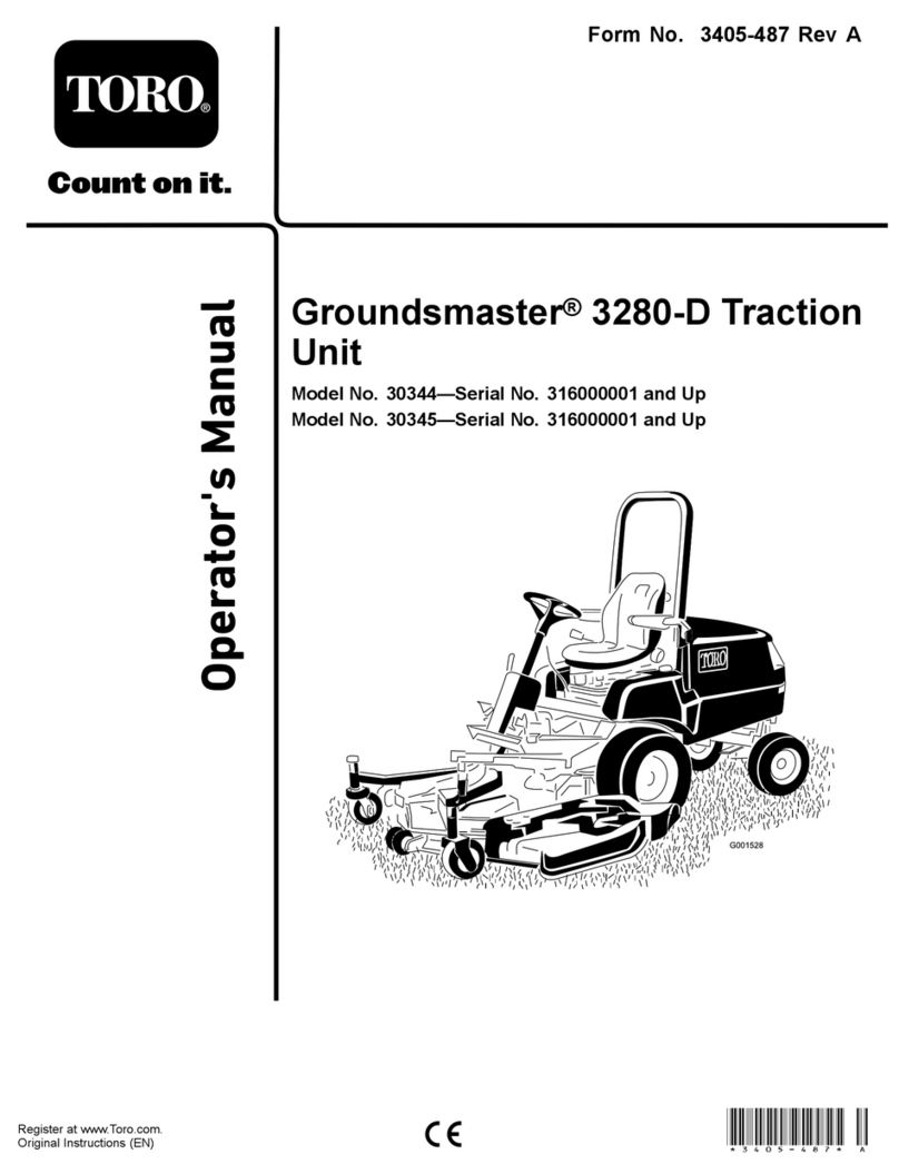
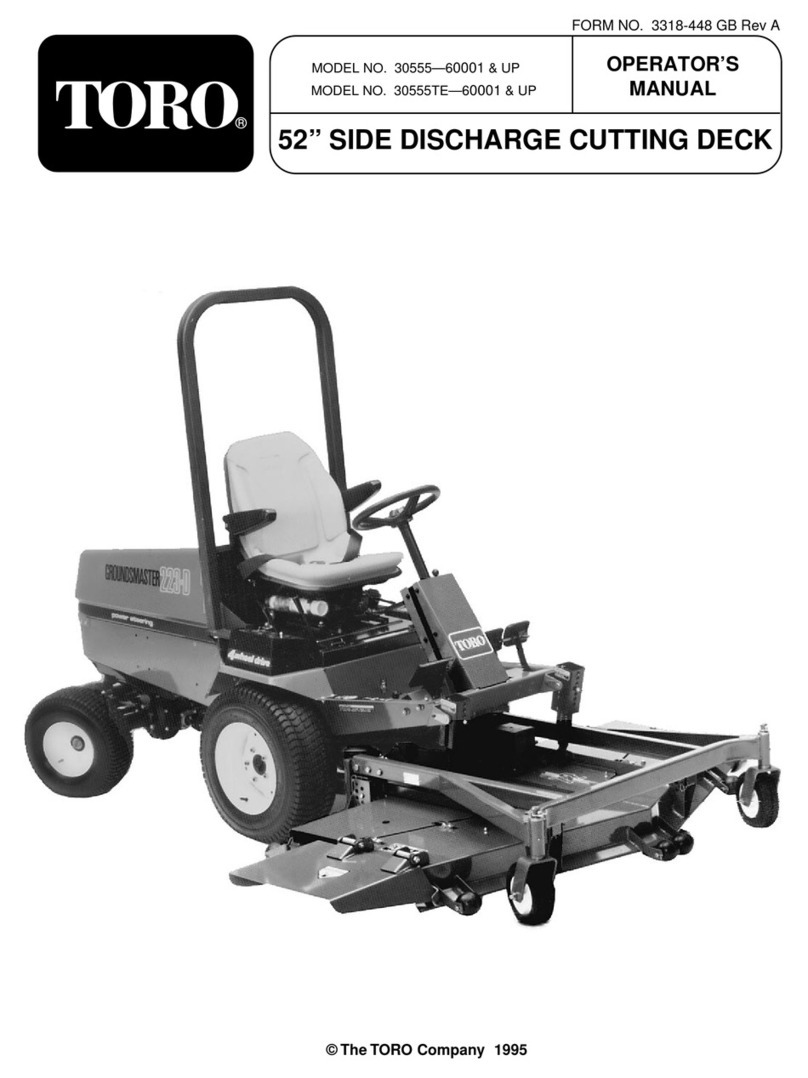
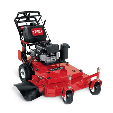
Toro Greensmaster Fixed Head Walk Behind Series User manual
Other Toro Lawn Mower manuals

Toro
Toro 30446 User manual
Toro
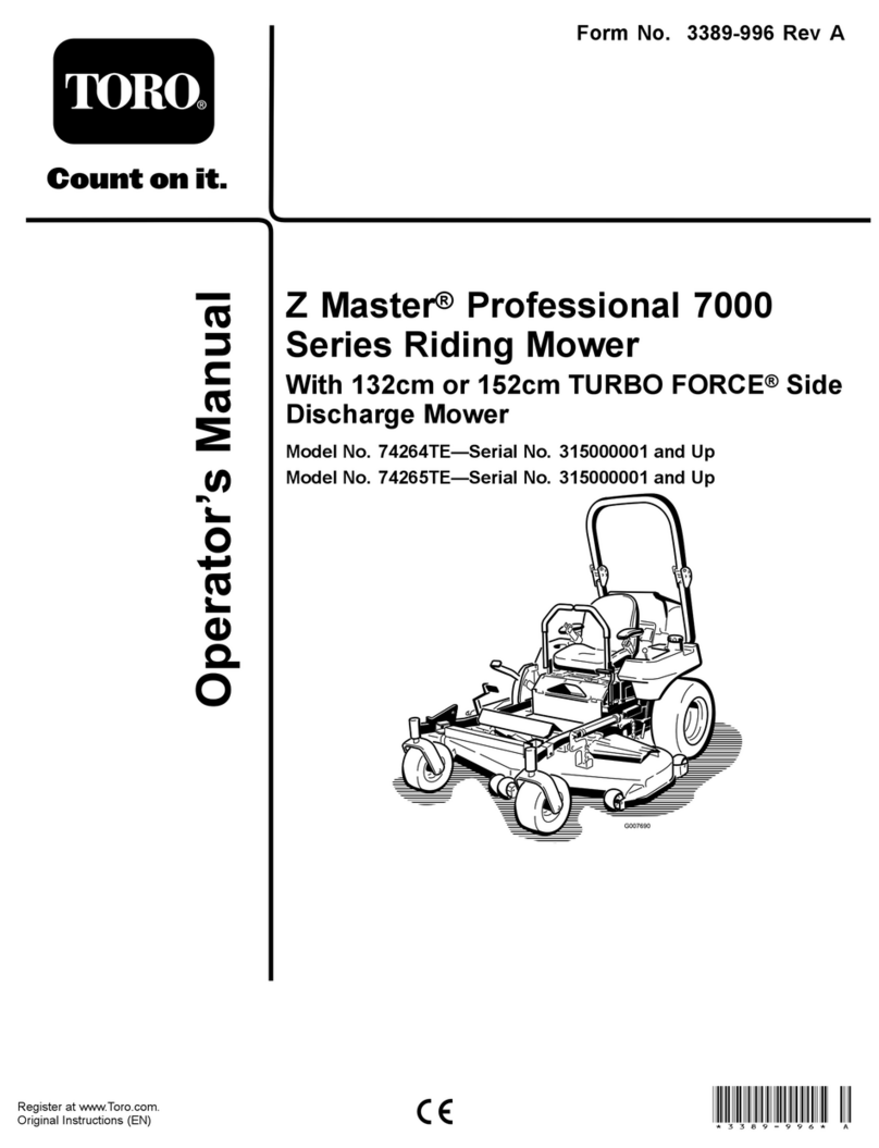
Toro Z Master Professional 7000 Series User manual
Toro
Toro 74256 User manual
Toro
Toro TimeCutter 6000 User manual
Toro
Toro Reelmaster 5 Blade User manual
Toro
Toro Z500 Series Z Master Manual
Toro
Toro 20833 User manual

Toro
Toro GrandStand 78596 User manual
Toro
Toro 30672 User manual
Toro
Toro Z Master 74919TE User manual
Popular Lawn Mower manuals by other brands

DEWEZE
DEWEZE ATM-725 Operation and service manual

Weed Eater
Weed Eater 180083 owner's manual

Husqvarna
Husqvarna Poulan Pro PP185A42 Operator's manual

Better Outdoor Products
Better Outdoor Products Quick Series Operator's manual

Cub Cadet
Cub Cadet 23HP Z-Force 60 Operator's and service manual

MTD
MTD 795, 792, 791, 790 Operator's manual
