Toro Reelmaster 5510-D User manual

FormNo.3417-925RevB
Reelmaster®5410-Dor5510-D
TractionUnit
ModelNo.03606—SerialNo.401334001andUp
ModelNo.03607—SerialNo.401334001andUp
Registeratwww.Toro.com.
OriginalInstructions(EN)*3417-925*B

ThisproductcomplieswithallrelevantEuropean
directives.Fordetails,pleaseseetheseparate
productspecicDeclarationofConformity(DOC)
sheet.
WARNING
CALIFORNIA
Proposition65Warning
Thisproductcontainsachemical
orchemicalsknowntotheStateof
Californiatocausecancer,birthdefects,
orreproductiveharm.
Dieselengineexhaustandsomeofits
constituentsareknowntotheStateof
Californiatocausecancer,birthdefects,
andotherreproductiveharm.
ItisaviolationofCaliforniaPublicResourceCode
Section4442or4443touseoroperatetheengineon
anyforest-covered,brush-covered,orgrass-covered
landunlesstheengineisequippedwithaspark
arrester,asdenedinSection4442,maintainedin
effectiveworkingorderortheengineisconstructed,
equipped,andmaintainedforthepreventionofre.
Theenclosedengineowner’smanualissupplied
forinformationregardingtheUSEnvironmental
ProtectionAgency(EPA)andtheCaliforniaEmission
ControlRegulationofemissionsystems,maintenance,
andwarranty.Replacementsmaybeorderedthrough
theenginemanufacturer.
Introduction
Thismachineisaride-on,reel-bladelawnmower
intendedtobeusedbyprofessional,hiredoperators
incommercialapplications.Itisprimarilydesigned
forcuttinggrassonwell-maintainedlawnsingolf
courses,parks,sportselds,andoncommercial
grounds.Itisnotdesignedforcuttingbrush,mowing
grassandothergrowthalongsidehighways,orfor
agriculturaluses.
Readthisinformationcarefullytolearnhowtooperate
andmaintainyourproductproperlyandtoavoid
injuryandproductdamage.Youareresponsiblefor
operatingtheproductproperlyandsafely.
Important:Tomaximizesafety,performance,
andproperoperationofthismachine,youmust
carefullyreadandfullyunderstandthecontents
ofthisOperator’sManual.Failuretofollow
theseoperatinginstructionsortoreceiveproper
trainingmayresultininjury.Formoreinformation
onsafeoperatingpractices,includingsafetytips
andtrainingmaterials,gotowww.Toro.com.
YoumaycontactTorodirectlyatwww.T oro.com
forproductsafetyandoperationtrainingmaterials,
accessoryinformation,helpndingadealer,orto
registeryourproduct.
Wheneveryouneedservice,genuineToroparts,or
additionalinformation,contactanAuthorizedService
DealerorT oroCustomerServiceandhavethemodel
andserialnumbersofyourproductready.Themodel
andserialnumbersareonaplatemountedonthe
leftsideoftheframeunderthefootrest.Writethe
numbersinthespaceprovided.
ModelNo.
SerialNo.
Thismanualidentiespotentialhazardsandhas
safetymessagesidentiedbythesafety-alertsymbol
(Figure1),whichsignalsahazardthatmaycause
seriousinjuryordeathifyoudonotfollowthe
recommendedprecautions.
g000502
Figure1
1.Safety-alertsymbol
Thismanualuses2wordstohighlightinformation.
Importantcallsattentiontospecialmechanical
informationandNoteemphasizesgeneralinformation
worthyofspecialattention.
©2017—TheToro®Company
8111LyndaleAvenueSouth
Bloomington,MN554202
Contactusatwww.Toro.com.
PrintedintheUSA
AllRightsReserved

Contents
Safety.......................................................................4
GeneralSafety...................................................4
EngineEmissionCertication.............................4
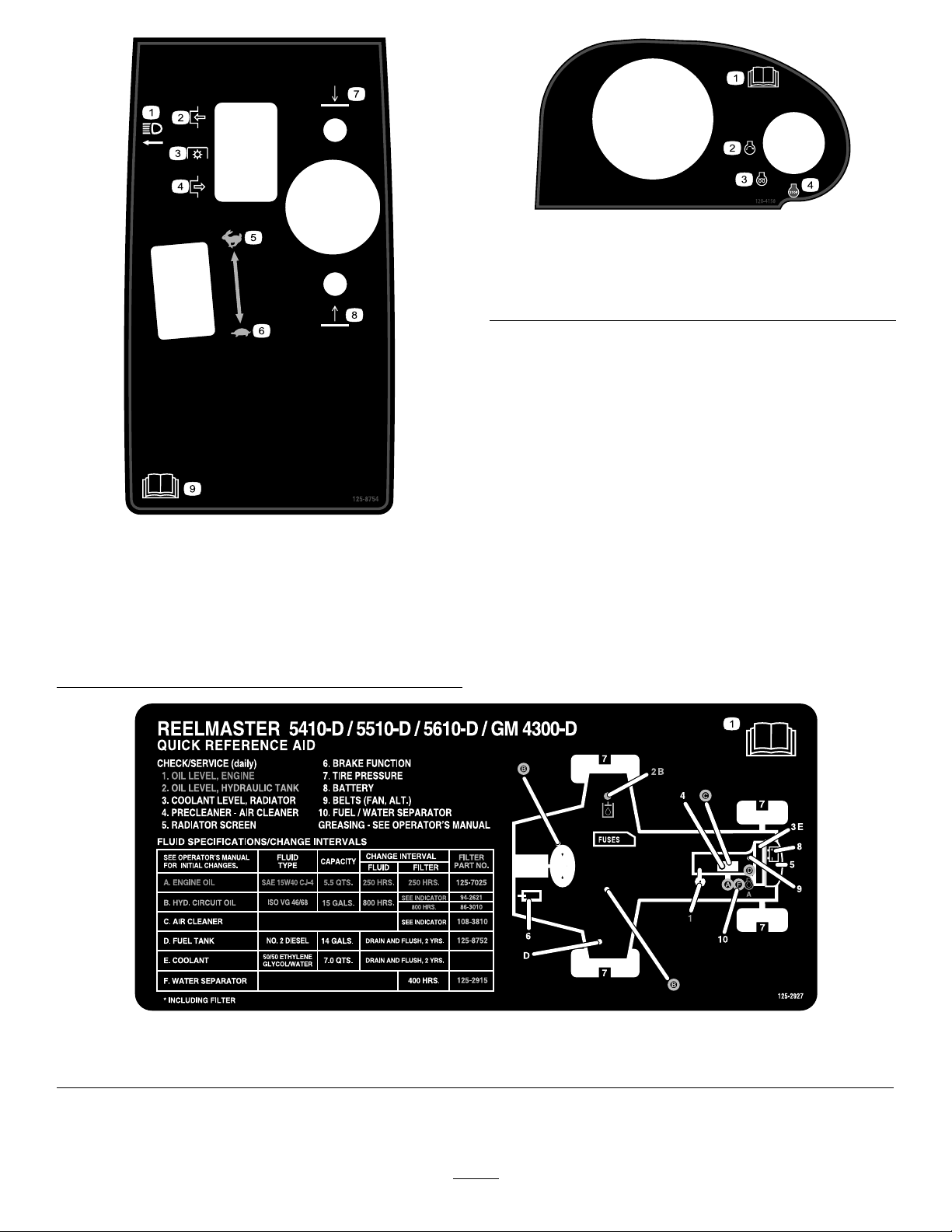
SafetyandInstructionalDecals..........................5
Setup........................................................................9
1AdjustingtheTirePressure............................10
2AdjustingtheControl-ArmPosition.................10
3InstallingtheCuttingUnits...............................11
4AdjustingtheTurf-Compensation
Spring...........................................................14
5UsingtheCutting-UnitKickstand....................15
6ReplacingtheWarningDecalforCE
Compliance...................................................15
ProductOverview...................................................16
Controls...........................................................16
Specications..................................................23
Attachments/Accessories.................................23
Operation................................................................24
BeforeOperationSafety...................................24
FillingtheFuelTank..........................................24
CheckingtheEngine-OilLevel..........................25
CheckingtheCoolingSystem...........................26
CheckingtheHydraulicFluid............................26
CheckingtheReel-to-BedknifeContact............27
CheckingtheT orqueoftheWheel
Nuts..............................................................27
BurnishingtheBrakes.......................................27
DuringOperationSafety...................................28
StartingandShuttingofftheEngine..................29
CuttingGrasswiththeMachine........................29
DieselParticulateFilterRegeneration...............30
AdjustingtheLift-ArmCounterbalance.............42
AdjustingtheLift-ArmTurnaround
Position.........................................................42
PushingorT owingtheMachine........................43
HaulingtheMachine.........................................43
JackingPoints..................................................44
UnderstandingtheDiagnosticLight..................44
CheckingtheInterlockSwitches.......................45
AfterOperationSafety......................................46
HaulingtheMachine.........................................46
Hydraulic-ValveSolenoidFunctions.................46
OperatingTips.................................................46
Maintenance...........................................................47
RecommendedMaintenanceSchedule(s)...........47
DailyMaintenanceChecklist.............................48
ServiceIntervalChart.......................................49
Pre-MaintenanceProcedures..............................49
Pre-MaintenanceSafety...................................49
Lubrication..........................................................49
GreasingtheBearingsandBushings................49
EngineMaintenance...........................................51
EngineSafety...................................................51
ServicingtheAirCleaner..................................51
ServicingtheEngineOil....................................53
ServicingtheDiesel-OxidationCatalyst
(DOC)andtheSootFilter..............................54
FuelSystemMaintenance...................................55
ServicingtheWaterSeparator.........................55
ServicingtheEngineFuelFilter........................55
CheckingtheFuelLinesand
Connections..................................................56
FuelPick-upTubeScreen.................................56
ElectricalSystemMaintenance...........................56
ElectricalSystemSafety...................................56
ServicingtheBattery.........................................56
CheckingtheFuses..........................................57
DriveSystemMaintenance..................................58
AdjustingtheTractionDriveforNeutral.............58
AdjustingtheRearWheelToe-in.......................59
CoolingSystemMaintenance..............................59
CoolingSystemSafety.....................................59
RemovingDebrisfromtheCooling
System..........................................................59
BrakeMaintenance.............................................60
AdjustingtheParkingBrakes............................60
AdjustingtheParking-BrakeLatch....................61
BeltMaintenance................................................61
ServicingtheAlternatorBelt.............................61
HydraulicSystemMaintenance...........................62
HydraulicSystemSafety...................................62
ChangingtheHydraulicFluid............................62
ReplacingtheHydraulicFilters.........................63
CheckingtheHydraulicLinesand
Hoses............................................................63
Hydraulic-SystemT estPorts.............................64
CuttingUnitSystemMaintenance........................65
CuttingUnitSafety............................................65
BacklappingtheCuttingUnits...........................65
Storage...................................................................66
PreparingtheTractionUnit...............................66
PreparingtheEngine........................................66
3

Safety
Thismachinehasbeendesignedtomeetorexceed
ENISO5395:2013(whenappropriatedecalsare
applied)andANSIB71.4-2017.
GeneralSafety
Thisproductiscapableofamputatinghandsand
feetandofthrowingobjects.Alwaysfollowallsafety
instructionstoavoidseriouspersonalinjury.
Usingthisproductforpurposesotherthanitsintended
usecouldprovedangeroustoyouandbystanders.
•Readandunderstandthecontentsofthis
Operator’sManualbeforestartingtheengine.
•Donotputyourhandsorfeetnearmoving
componentsofthemachine.
•Donotoperatethemachinewithoutallguards
andothersafetyprotectivedevicesinplaceand
workingonthemachine.
•Useyourfullattentionwhileoperatingthe
machine.Donotengageinanyactivitythat
causesdistraction;otherwise,injuryorproperty
damagemayoccur.
•Keepclearofanydischargeopening.Keep
bystandersandpetsasafedistanceawayfrom
themachine.
•Keepchildrenoutoftheoperatingarea.Never
allowchildrentooperatethemachine.
•Stopthemachineandshutofftheenginebefore
servicing,fueling,oruncloggingthemachine.
Improperlyusingormaintainingthismachinecan
resultininjury.Toreducethepotentialforinjury,
complywiththesesafetyinstructionsandalwayspay
attentiontothesafety-alertsymbol,whichmeans
Caution,Warning,orDanger—personalsafety
instruction.Failuretocomplywiththeseinstructions
mayresultinpersonalinjuryordeath.
Youcanndadditionalsafetyinformationwhere
neededthroughoutthisOperator’sManual.
EngineEmission
Certication
TheengineinthismachineisEPATier4Finaland
stage3bcompliant.
4

SafetyandInstructionalDecals
Safetydecalsandinstructionsareeasilyvisibletotheoperatorandarelocatednearanyarea
ofpotentialdanger.Replaceanydecalthatisdamagedormissing.
decal93-7272
93-7272
1.Cutting/dismembermenthazard,fan—stayawayfrom
movingparts.
decal93-6696
93–6696
1.Storedenergyhazard—readtheOperator'sManual.
decal106-6754
106-6754
1.Warning—donottouchthehotsurface.
2.Cutting/dismembermenthazard,fanandentanglement
hazard,belt—stayawayfrommovingparts.
decal110-0986
110-0986
1.Pressthebrakepedalandparkingbrakepedaltosetthe
parkingbrake.
2.Pressthebrakepedaltoapplythebrake.
3.Pressthetractionpedaltomovethemachineforward.
4.Reelenabledmode
5.Transportmode
decal106-6755
106-6755
1.Enginecoolantunder
pressure.
3.Warning—donottouchthe
hotsurface.
2.Explosionhazard—read
theOperator'sManual.
4.Warning—readthe
Operator'sManual.
decal110-9642
110-9642
1.Storedenergyhazard—readtheOperator'sManual.
2.Movethecotterpintotheholeclosesttotherodbracket
andthenremovetheliftarmandpivotyoke.
5

r:\decal117-0169
117-0169
1.ReadtheOperator'sManual.
2.Powerpoint(10A)
3.Headlights(10A)
4.Power(10A)
5.Enginestart(15A)
6.Optionalairrideseatsuspension(10A)
7.EnginecomputermanagementC(10A)
8.EnginecomputermanagementB(10A)
9.EnginecomputermanagementA(10A)
decal110-8921
110-8921
1.Tractionunitspeed
2.Slow
3.Fast
decal117-2718
117–2718
decal133-2930
133-2930
1.Warning—readtheOperator'sManual;donotoperatethis
machineunlessyouaretrained.
4.Tippinghazard—slowthemachinebeforeturning;donotturn
athighspeeds;driveonlyonslopeswiththecuttingunits
lowered;alwayswearaseatbelt.
2.Warning—wearhearingprotection.5.Warning—donotparkonslopes;locktheparkingbrake,shut
offtheengineandremovetheignitionkeybeforeleavingthe
machine.
3.Thrownobjecthazard—keepbystandersasafedistance
awayfromthemachine.
6.Warning—readtheOperator'sManual;donottowthe
machine.
6

decal133-2931
133-2931
(AfxoverPartNo.133-2930)
Note:Thismachinecomplieswiththeindustrystandardstabilitytestinthestaticlateralandlongitudinaltestswiththemaximum
recommendedslopeindicatedonthedecal.ReviewtheinstructionsforoperatingthemachineonslopesintheOperator’sManualas
wellastheconditionsinwhichyouwouldoperatethemachinetodeterminewhetheryoucanoperatethemachineintheconditions
onthatdayandatthatsite.Changesintheterraincanresultinachangeinslopeoperationforthemachine.Ifpossible,keepthe
cuttingunitsloweredtothegroundwhileoperatingthemachineonslopes.Raisingthecuttingunitswhileoperatingonslopescan
causethemachinetobecomeunstable.
1.Warning—readtheOperator'sManual;donotoperatethis
machineunlessyouaretrained.
4.Tippinghazard—donotdriveacrossordownslopesgreater
than15degrees;onlydriveonslopeswiththecuttingunits
lowered;alwayswearaseatbelt
2.Warning—wearhearingprotection.5.Warning—donotparkonslopes;engagetheparkingbrake,
shutofftheengine,andremovetheignitionkeybeforeleaving
themachine.
3.Thrownobjecthazard—keepbystandersasafedistance
awayfromthemachine
6.Warning—readtheOperator'sManual;donottowthe
machine.
decalbatterysymbols
BatterySymbols
Someorallofthesesymbolsareonyourbattery.
1.Explosionhazard6.Keepbystandersasafe
distancefromthebattery.
2.Nore,opename,or
smoking
7.Weareyeprotection;
explosivegasescan
causeblindnessandother
injuries.
3.Causticliquid/chemical
burnhazard
8.Batteryacidcancause
blindnessorsevereburns.
4.Weareyeprotection.9.Flusheyesimmediately
withwaterandgetmedical
helpfast.
5.ReadtheOperator's
Manual.
10.Containslead;donot
discard
decal93-6689
93–6689
1.Danger—noriders.
7

decal125-8754
125–8754
1.Headlights6.Slow
2.Engage7.Lowerthecuttingunits
3.Powertake-off(PTO)8.Raisethecuttingunits
4.Disengage9.ReadtheOperator’s
Manual.
5.Fast
decal120-4158
120–4158
1.ReadtheOperator’s
Manual.
3.Engine—preheat
2.Engine—start4.Engine—stop
decal125-2927
125–2927
1.ReadtheOperator’sManualformaintenanceinformation.
8

Setup
LooseParts
Usethechartbelowtoverifythatallpartshavebeenshipped.
ProcedureDescriptionQty.Use
1Nopartsrequired–Adjustthetirepressure.
2Nopartsrequired–Adjustthecontrol-armposition.
Right,fronthoseguide1
3Left,fronthoseguide1Installthecuttingunits.
4Nopartsrequired–Adjusttheturf-compensationspring.
5Cutting-unitkickstand1Installthecutting-unitkickstand.
6Warningdecal1ReplacethedecalforCEcompliance.
MediaandAdditionalParts
DescriptionQty.Use
Operator'sManual1ReadtheOperator'sManualbeforeoperatingthemachine.
Engineowner’smanual1Readthemanualbeforeoperatingtheengine.
Cuttingperformancepaper1Adjustthecutting-unitbedknifetoreel.
Shim1Adjustthecutting-unitbedknifetoreel.
Note:Determinetheleftandrightsidesofthemachinefromthenormaloperatingposition.
9

1
AdjustingtheTirePressure
NoPartsRequired
Procedure
Thetiresareover-inatedforshipping.Therefore,
releasesomeoftheairtoreducethepressure.
Correctairpressureinthefrontandreartiresis83
to103kPa(12to15psi).
Important:Maintainevenpressureinalltiresto
ensurethatthereisuniformcontactwiththeturf.
2
AdjustingtheControl-Arm
Position
NoPartsRequired
Procedure
Thecontrol-armpositioncanbeadjustedforyour
comfort.
1.Loosenthe2boltssecuringthecontrolarmto
theretainingbracket(Figure2).
g004152
Figure2
1.Controlarm3.Bolt
2.Retainingbrackets
2.Rotatethecontrolarmtothedesiredposition
andtightenthe2bolts.
10

3
InstallingtheCuttingUnits
Partsneededforthisprocedure:
1Right,fronthoseguide
1Left,fronthoseguide
Procedure
1.Removethereelmotorsfromtheshipping
brackets.
Note:Discardtheshippingbrackets.
2.Removethecuttingunitsfromthecartons.
3.Assembleandadjustthecuttingunitsas
describedintheOperator'sManualforthe
cuttingunits.
4.Makesurethatthecounterweight(Figure3)is
installedtotheproperendofeachcuttingunit
asdescribedintheOperator'sManualforthe
cuttingunits.
g003320
Figure3
1.Counterweight
5.Mounttheturf-compensationspringtothesame
sideofthecuttingunitasthereel-drivemotor.
Repositiontheturf-compensationspringas
follows:
Note:Allcuttingunitsareshippedwiththe
turf-compensationspringmountedtotheright
sideofthecuttingunit.
A.Removethe2carriageboltsandnuts
securingtherodbrackettothecutting-unit
tabs(Figure4).
g003949
Figure4
1.Turf-compensationspring3.Springtube
2.Rodbracket
B.Removetheangenutsecuringthe
spring-tubebolttothecarrier-frametab
(Figure4).Removetheassembly.
C.Mountthespring-tubebolttotheopposite
tabonthecarrierframeandsecurewiththe
angenut.
Note:Positiontheboltheadtotheouter
sideofthetabasshowninFigure5.
g003967
Figure5
1.Oppositecarrier-frametab2.Rodbracket
D.Mounttherodbrackettothecutting-unit
tabswiththecarriageboltsandnuts(Figure
5).
Important:Oncuttingunit4(leftfront)
andcuttingunit5(rightfront),usethe
rod-bracket-mountingnutstoinstall
thehoseguidestothefrontofthe
cutting-unittabs(Figure6andFigure7).
Thehoseguidesshouldleantowardthe
centercuttingunit(Figure7andFigure
8).
Note:Wheninstallingorremovingthe
cuttingunits,makesurethatthehairpin
cotterisinstalledinthespring-rodholenext
totherodbracket.Whennotinstallingor
removingthecuttingunits,thehairpincotter
mustbeinstalledintheholeintheendof
therod.
11

g030896
Figure6
1.Cuttingunit15.Cuttingunit5
2.Cuttingunit26.Reelmotor
3.Cuttingunit37.Weight
4.Cuttingunit4
g015160
Figure7
1.Hoseguide(cuttingunit4
shown)
3.Nut
2.Rodbracket
g019284
Figure8
1.Hoseguidesmustleantowardthecentercuttingunit.
6.Lowerallliftarmscompletely.
7.Removethesnapperpinandthecapfromthe
lift-arm-pivotyoke(Figure9).
12

g003975
Figure9
1.Snapperpin2.Cap
8.Forthefrontcuttingunits,slideacuttingunit
undertheliftarmwhileinsertingthecarrier-frame
shaftupintothelift-arm-pivotyoke(Figure10).
g003977
Figure10
1.Liftarm3.Lift-arm-pivotyoke
2.Carrier-frameshaft
9.Usethefollowingprocedureontherearcutting
unitswhentheheightofcutisabove19mm
(3/4inch).
A.Removethelynchpinandwashersecuring
thelift-arm-pivotshafttotheliftarmand
slidethelift-arm-pivotshaftoutofthelift
arm(Figure11).
g003979
Figure11
1.Lynchpinandwasher
B.Insertthelift-armyokeontothecarrier-frame
shaft(Figure10).
C.Insertthelift-armshaftintotheliftarmand
secureitwiththewasherandlynchpin
(Figure11).
10.Insertthecapoverthecarrier-frameshaftand
lift-armyoke.
11.Securethecapandthecarrier-frameshaftto
thelift-armyokewiththesnapperpin(Figure9).
Note:Usetheslotifasteeringcuttingunitis
desiredorusetheholeifthecuttingunitistobe
lockedinposition
12.Securethelift-armchaintothechainbracket
withthesnapperpin(Figure12).
Note:Usethenumberofchainlinksdescribed
intheOperator'sManualforthecuttingunit.
g003948
Figure12
1.Lift-armchain3.Pin
2.Chainbracket
13.Oncuttingunit4(leftfront)andcuttingunit5
(rightfront),insertthereel-motorhosesintothe
respectivehoseguide.
14.Coatthesplineshaftofthereelmotorwithclean
grease.
15.Oilthereel-motorO-ringandinstallitontothe
motorange.
16.Installthemotorbyrotatingitclockwisesothat
themotorangesclearthebolts(Figure13).
13

Note:Rotatethemotorcounterclockwiseuntil
theangesencircletheboltsandthentighten
thebolts.
Important:Makesurethatthereel-motor
hosesarenottwisted,kinked,oratriskof
beingpinched.
g004127
Figure13
1.Reel-drivemotor2.Mountingbolts
4
Adjustingthe
Turf-CompensationSpring
NoPartsRequired
Procedure
Theturf-compensationspringtransfersweightfrom
thefronttotherearroller(Figure14).Thishelps
toreduceawavepatternintheturf,alsoknownas
marcellingorbobbing.
Important:Makespringadjustmentswiththe
cuttingunitmountedtothetractionunit,pointing
straightaheadandloweredtotheground.
1.Makesurethatthehairpincotterisinstalledin
therearholeinthespringrod(Figure14).
g003863
Figure14
1.Turf-compensationspring3.Springrod
2.Hairpincotter4.Hexnuts
2.Tightenthehexnutsonthefrontendofthe
springroduntilthecompressedlengthofthe
springis12.7cm(5inches)for5-inchcutting
unitsor15.9cm(6.25inches)for7-inchcutting
units(Figure14).
Note:Whenoperatingonroughterrain,
decreasethespringlengthby12.7mm(1/2
inch).Thisslightlydecreasestheground
following.
14

5
UsingtheCutting-Unit
Kickstand
Partsneededforthisprocedure:
1Cutting-unitkickstand
Procedure
Wheneveryouneedtotipthecuttingunittoexpose
thebedknife/reel,propuptherearofthecuttingunit
withthekickstandtomakesurethatthenutsonthe
backendofthebedbar-adjustingscrewsarenot
restingontheworksurface(Figure15).
g003985
Figure15
1.Cutting-unitkickstand
Securethekickstandtothechainbracketwiththe
snapperpin(Figure16).
g004144
Figure16
1.Chainbracket3.Cutting-unitkickstand
2.Snapperpin
6
ReplacingtheWarning
DecalforCECompliance
Partsneededforthisprocedure:
1Warningdecal
Procedure
OnmachinesrequiringCECompliance,afxtheCE
warningdecal(PartNo.133-2931)overthestandard
warningdecal(PartNo.133-2930).
15

ProductOverview
g216864
Figure17
1.Enginehood5.Seatadjustments
2.Seat6.Frontcuttingunits
3.Controlarm7.Rearcuttingunits
4.Steeringwheel
Controls
Seat-AdjustingKnobs
Theseat-adjustingleverallowsyoutoadjust
theseatforwardandrearward(Figure18).The
weight-adjustingknobadjuststheseatforyourweight.
Theweightgaugeindicateswhentheseatisadjusted
toyourweight.Theheight-adjustingknobadjuststhe
seatforyourheight.
g003954
Figure18
1.Weightgauge3.Height-adjustingknob
2.Weight-adjustingknob4.Adjustinglever
TractionPedal
Thetractionpedalcontrolstheforwardandreverse
operation(Figure19).Pressthetopofthepedal
tomoveforwardandthebottomtomoverearward.
Groundspeeddependsonhowfaryoupressthe
pedal.Fornoload,maximumgroundspeed,setthe
enginespeedtotheFASTpositionandfullypressthe
pedal.
Tostop,reducefootpressureonthetractionpedal
andallowittoreturntothecenterposition.
g003955
Figure19
1.Tractionpedal4.Brakepedal
2.Mow-speedlimiter5.Parkingbrake
3.Spacers6.Tilt-steeringpedal
Mow-SpeedLimiter
Whenthemow-speedlimiterisippedup,itcontrols
themowspeedandallowsthecuttingunitstobe
engaged(Figure19).Eachspaceradjuststhe
mowingspeedby0.8km/h(0.5mph).Themore
spacersyouhaveonthetopofthebolt,theslowerthe
mowingspeed.T otransportthemachine,ipbackthe
mow-speedlimiterforthemaximumtransportspeed.
BrakePedal
Pressthebrakepedaltostopthemachine(Figure19).
ParkingBrake
Toengagetheparkingbrake,pushdownonthebrake
pedalandpressthetopforwardtolatch(Figure19).
Toreleasetheparkingbrake,pressthebrakepedal
untiltheparking-brakelatchretracts.
16

Tilt-SteeringPedal
Totiltthesteeringwheeltowardyou,pressthefoot
pedaldown,pullthesteeringtowertowardyouto
themostcomfortableposition,andreleasethepedal
(Figure19).
Engine-SpeedSwitch
Theengine-speedswitchhas2modestochangethe
enginespeed(Figure20).Bymomentarilytappingthe
switch,youcanchangetheenginespeedin100rpm
increments.Ifyouholdtheswitchdown,theengine
automaticallymovestoHighorLowidle,depending
onwhichendoftheswitchyoupress.
g021208
Figure20
1.Lowermow/raisecontrol
lever
4.Enable/disableswitch
2.Keyswitch5.Engine-speedswitch
3.InfoCenter6.Headlightswitch
Enable/DisableSwitch
Usetheenable/disableswitchinconjunctionwiththe
lowermow/raisecontrollevertooperatethecutting
units(Figure20).
InfoCenter
TheInfoCenterLCDdisplayshowsinformationabout
yourmachine,suchastheoperatingstatus,various
diagnostics,andotherinformationaboutthemachine
(Figure20).
KeySwitch
Thekeyswitchhas3positions:OFF,ON/RUN,and
START(Figure20).
LowerMow/RaiseControlLever
Thisleverraisesandlowersthecuttingunitsandalso
startsandstopsthecuttingunitswhenthecutting
unitsareenabledintheMOWmode(Figure20).You
cannotlowerthecuttingunitswhenthemow/transport
leverisintheTRANSPORTposition.
HeadlightSwitch
Pivottheswitchdownwardtoturnontheheadlights
(Figure20).
BacklapLevers
Usethebacklapleversinconjunctionwiththelower
mow/raisecontrolleverforbacklappingthereels
(Figure21).
g021209
Figure21
1.Backlaplevers
17

Hydraulic-Filter-Restriction
Indicator
Withtheenginerunningatnormaloperating
temperature,ensurethattheindicatorisinthegreen
zone(Figure22).Whentheindicatorisinthered
zone,changethehydrauliclters.
g004132
Figure22
1.Hydraulic-lter-restrictionindicator
PowerPoint
Thepowerpointisa12Vpowersupplyforelectronic
devices(Figure23).
g004133
Figure23
1.Powerpoint
UsingtheInfoCenterLCDDisplay
TheInfoCenterLCDdisplayshowsinformationabout
yourmachine,suchastheoperatingstatus,various
diagnostics,andotherinformationaboutthemachine
(Figure24).Thereisasplashscreenandmain
informationscreenoftheInfoCenter.Youcanswitch
betweenthesplashscreenandmaininformation
screen,atanytime,bypressinganyoftheInfoCenter
buttonsandthenselectingtheappropriatedirectional
arrow.
g020650
Figure24
1.Indicatorlight3.Middlebutton
2.Rightbutton4.Leftbutton
•LeftButton,MenuAccess/BackButton—Press
thisbuttontoaccesstheInfoCentermenus.
Youcanuseittobackoutofanymenuyouare
currentlyusing.
•MiddleButton—Pressthisbuttontoscrolldown
menus.
•RightButton—Pressthisbuttontoopenamenu
wherearightarrowindicatesadditionalcontent.
Note:Thepurposeofeachbuttonmaychange
dependingonwhatisrequiredatthetime.Each
buttonislabeledwithanicondisplayingitscurrent
function.
18

InfoCenterIconDescription
Hoursremaininguntilservice
Resettheservicehours
SERVICEDUEIndicateswhenscheduledservice
shouldbeperformed
Enginerpm/status—indicatesthe
enginespeed(rpm)
Hourmeter
Infoicon
Fast
Slow
Fuellevel
Stationaryregenerationisrequired.
Theglowplugsareactive.
Raisethecuttingunits.
Lowerthecuttingunits.
Sitintheseat.
ParkingbrakeisOn.
Therangeishigh(transport).
Neutral
Therangeislow(mow).
Engine-coolanttemperature(°Cor
°F)
Temperature(hot)
ThePTOisengaged.
Notallowed
Starttheengine.
Shutofftheengine.
Engine
Keyswitch
Thecuttingunitsarelowering.
Thecuttingunitsareraising.
PINcode
CANbus
InfoCenter
Badorfailed
Bulb
OutputofTECcontrollerorcontrol
wireinharness
Switch
Releasetheswitch.
Changetotheindicatedstate.
Symbolsareoften
combinedtoform
sentences.Some
examplesareshown
below
PutthemachineintoNeutral.
Enginestartisdenied.
Engineshutdown
Enginecoolantistoohot.
Reset-standbyregenerationrequest
Parkedorrecoveryregeneration
request
Aparkedorrecoveryregenerationis
processing.
19

Highexhausttemperature
DPFash-accumulation
notication—RefertoDPFAsh
Accumulation(page31)fordetails.
Sitdownorengagetheparkingbrake
UsingtheMenus
ToaccesstheInfoCentermenusystem,pressthe
menuaccessbuttonwhileatthemainscreen.This
bringsyoutothemainmenu.Refertothefollowing
tablesforasynopsisoftheoptionsavailablefrom
themenus:
MainMenu
MenuItemDescription
FaultsContainsalistoftherecent
machinefaults.Refertothe
ServiceManualorcontactyour
authorizedT orodistributorfor
moreinformationontheFaults
menuandtheinformation
containedthere.
ServiceContainsinformationonthe
machinesuchashoursof
usecountersandothersimilar
numbers.
DiagnosticsDisplaysthestateofeach
machineswitch,sensorand
controloutput.Youcanuse
thistotroubleshootcertain
issuesasitquicklytellsyou
whichmachinecontrolsareon
andwhichareoff.
SettingsAllowsyoutocustomizeand
modifycongurationvariables
ontheInfoCenterdisplay.
AboutListsthemodelnumber,serial
number,andsoftwareversion
ofyourmachine.
Service
MenuItemDescription
HoursListsthetotalnumberofhours
thatthemachine,engineand
PTOhavebeenon,aswell
asthenumberofhoursthe
machinehasbeentransported
andservicedue.
CountsListsnumerouscountsthe
machinehasexperienced.
DPFRegenerationThedieselparticulatelter
regenerationoptionandDPF
submenus
InhibitRegenUsetocontrolreset
regeneration
ParkedRegenUsetoinitiateaparked
regeneration
LastRegenListsthenumberhourssince
thelastreset,parked,or
recoveryregeneration
RecoverRegenUsetoinitiatearecovery
regeneration
Diagnostics
MenuItemDescription
CuttingUnitsIndicatestheinputs,qualiers
andoutputsforraisingand
loweringthecuttingunits.
Hi/LowRangeIndicatestheinputs,qualiers
andoutputsfordrivingin
transportmode.
PTOIndicatestheinputs,qualiers
andoutputsforenablingthe
PTOcircuit.
EngineRunIndicatestheinputs,qualiers
andoutputsforstartingthe
engine.
BacklapIndicatestheinputs,qualiers
andoutputsforoperatingthe
backlapfunction.
Settings
MenuItemDescription
UnitsControlstheunitsusedonthe
InfoCenter.Themenuchoices
areEnglishorMetric
LanguageControlsthelanguageused
ontheInfoCenter*.
LCDBacklightControlsthebrightnessofthe
LCDdisplay.
LCDContrastControlsthecontrastofthe
LCDdisplay.
FrontBacklapReelSpeedControlsthespeedofthefront
reelsinbacklapmode.
RearBacklapReelSpeedControlsthespeedoftherear
reelsinbacklapmode.
ProtectedMenusAllowsapersonauthorized
byyourcompanywiththe
PINcodetoaccessprotected
menus.
AutoIdleControlstheamountoftime
allowedbeforereturningthe
enginetolowidlewhenthe
machineisstationary.
BladeCountControlsthenumberofblades
onthereelforreelspeed.
MowSpeedControlsthegroundspeedfor
determiningthereelspeed.
20
This manual suits for next models
3
Table of contents
Other Toro Lawn Mower manuals

Toro
Toro Recycler 20353 User manual

Toro
Toro 74241 User manual

Toro
Toro TimeCutter ZD Series Manual

Toro
Toro Z Master Commercial 3000 User manual

Toro
Toro 74806 User manual

Toro
Toro Recycler 20349 User manual

Toro
Toro 04022 Greensmaster Flex 21 User manual

Toro
Toro 30253 User manual

Toro
Toro 70089 User manual

Toro
Toro GrandStand HDX 72514 User manual

Toro
Toro 74410 User manual

Toro
Toro Recycler 20998 User manual

Toro
Toro Groundsmaster 4300-D User manual

Toro
Toro 74218 User manual

Toro
Toro LT3340 User manual

Toro
Toro TimeCutter Z4235 74365 User manual

Toro
Toro 30450 User manual

Toro
Toro 20814 User manual

Toro
Toro 8125 User manual

Toro
Toro 20319 User manual