Toro RAKE-O-VAC 07052 User manual

Operator’s Manual
Domestic English (EN)
Form No. 3329–240
66” Rake–O–Vac Sweeper
PTO and Engine Driven
Model No. 07050–220000001 and up
Model No. 07052–220000001 and up

2
All Rights Reserved
Printed in the USA
2002 by The Toro Company
8111 Lyndale Avenue South
Bloomington, MN 55420-1196
CALIFORNIA
Proposition 65 Warning
The engine exhaust from this product contains
chemicals known to the State of California to cause
cancer, birth defects, or other reproductive harm.
Warning
Important The engine in this product is not equipped
with a spark arrester muffler. It is a violation of California
Public Resource Code Section 4442 to use or operate this
engine on any forest-covered, brush-covered, or
grass-covered land as defined in CPRC 4126. Other states
or federal areas may have similar laws.
This spark ignition system complies with Canadian
ICES-002.
Ce système d’allumage par étincelle de véhicule est
conforme à la norme NMB-002 du Canada.
Contents
Page
Introduction 3. . . . . . . . . . . . . . . . . . . . . . . . . . . . . . . .
Safety 3. . . . . . . . . . . . . . . . . . . . . . . . . . . . . . . . . . . . .
Safety and Instruction Decals 5. . . . . . . . . . . . . . . .
Specifications 7. . . . . . . . . . . . . . . . . . . . . . . . . . . . . . .
Dimensions and Weights (approx.) 7. . . . . . . . . . .
Optional Equipment 7. . . . . . . . . . . . . . . . . . . . . . .
Setup 8. . . . . . . . . . . . . . . . . . . . . . . . . . . . . . . . . . . . .
Remove, Activate And Charge Battery 8. . . . . . . .
Install Battery 8. . . . . . . . . . . . . . . . . . . . . . . . . . . .
Mount Sweeper To Prime Mover 9. . . . . . . . . . . . .
Connecting Drive Shaft to Prime Mover PTO Shaft 10
Removing Sweeper From Prime Mover 10. . . . . . . .
Before Operating 11. . . . . . . . . . . . . . . . . . . . . . . . . . . .
Check Engine Oil 11. . . . . . . . . . . . . . . . . . . . . . . . .
Check Clutch Housing Oil 11. . . . . . . . . . . . . . . . . .
Fill Fuel Tank 12. . . . . . . . . . . . . . . . . . . . . . . . . . . .
Check Tire Pressure 12. . . . . . . . . . . . . . . . . . . . . . .
Transport Hooks 13. . . . . . . . . . . . . . . . . . . . . . . . . .
Adjust Reel Support Arm 13. . . . . . . . . . . . . . . . . . .
Adjust Rake Depth 13. . . . . . . . . . . . . . . . . . . . . . . .
Adjust Rubber Flap 14. . . . . . . . . . . . . . . . . . . . . . .
Page
Operation 14. . . . . . . . . . . . . . . . . . . . . . . . . . . . . . . . . .
Controls 14. . . . . . . . . . . . . . . . . . . . . . . . . . . . . . . .
Starting Instructions (Engine Driven) 15. . . . . . . . .
Stopping Instructions 16. . . . . . . . . . . . . . . . . . . . . .
Starting Instructions (PTO Driven) 16. . . . . . . . . . .
Operating Tips 16. . . . . . . . . . . . . . . . . . . . . . . . . . .
Inspection And Cleanup After Operation 16. . . . . . .
Maintenance 17. . . . . . . . . . . . . . . . . . . . . . . . . . . . . . . .
Lubrication 17. . . . . . . . . . . . . . . . . . . . . . . . . . . . . .
Oil Drive Chain 18. . . . . . . . . . . . . . . . . . . . . . . . . .
Oil Sweeper Jack 18. . . . . . . . . . . . . . . . . . . . . . . . .
Changing Engine Oil and Filter 18. . . . . . . . . . . . . .
General Air Cleaner Maintenance 19. . . . . . . . . . . .
Servicing Air Cleaner 19. . . . . . . . . . . . . . . . . . . . . .
Replacing Spark Plugs 19. . . . . . . . . . . . . . . . . . . . .
Removing Debris From Engine 20. . . . . . . . . . . . . .
Replace Fuel Filter 20. . . . . . . . . . . . . . . . . . . . . . . .
Changing Clutch Housing Oil 20. . . . . . . . . . . . . . .
Adjusting Clutch 20. . . . . . . . . . . . . . . . . . . . . . . . . .
Changing Rubber Flap 21. . . . . . . . . . . . . . . . . . . . .
Cleaning Blower Housing 21. . . . . . . . . . . . . . . . . .
Adjusting Belts 22. . . . . . . . . . . . . . . . . . . . . . . . . . .
Adjusting Drive Chain 24. . . . . . . . . . . . . . . . . . . . .
Changing Gear Box Oil 25. . . . . . . . . . . . . . . . . . . .
Gear Box Removal 25. . . . . . . . . . . . . . . . . . . . . . . .
Locking Collar Removal 26. . . . . . . . . . . . . . . . . . .
Pulley Removal 26. . . . . . . . . . . . . . . . . . . . . . . . . .
Flex Tip Reel Removal 26. . . . . . . . . . . . . . . . . . . . .
Thatcher Installation 27. . . . . . . . . . . . . . . . . . . . . . .
Flex Tip Rake Rod Or Finger Plate Replacement 27
Flex Tip Rake Tine Replacement 28. . . . . . . . . . . . .
Brush Half Replacement 28. . . . . . . . . . . . . . . . . . . .
Changing Tires 29. . . . . . . . . . . . . . . . . . . . . . . . . . .
Battery Care 29. . . . . . . . . . . . . . . . . . . . . . . . . . . . .
The Toro General Commercial Products Warranty 32. .
3
Introduction
Read this manual carefully to learn how to operate and
maintain your product properly. The information in this
manual can help you and others avoid injury and product
damage. Although Toro designs and produces safe
products, you are responsible for operating the product
properly and safely.
Whenever you need service, genuine Toro parts, or
additional information, contact an Authorized Service
Dealer or Toro Customer Service and have the model and
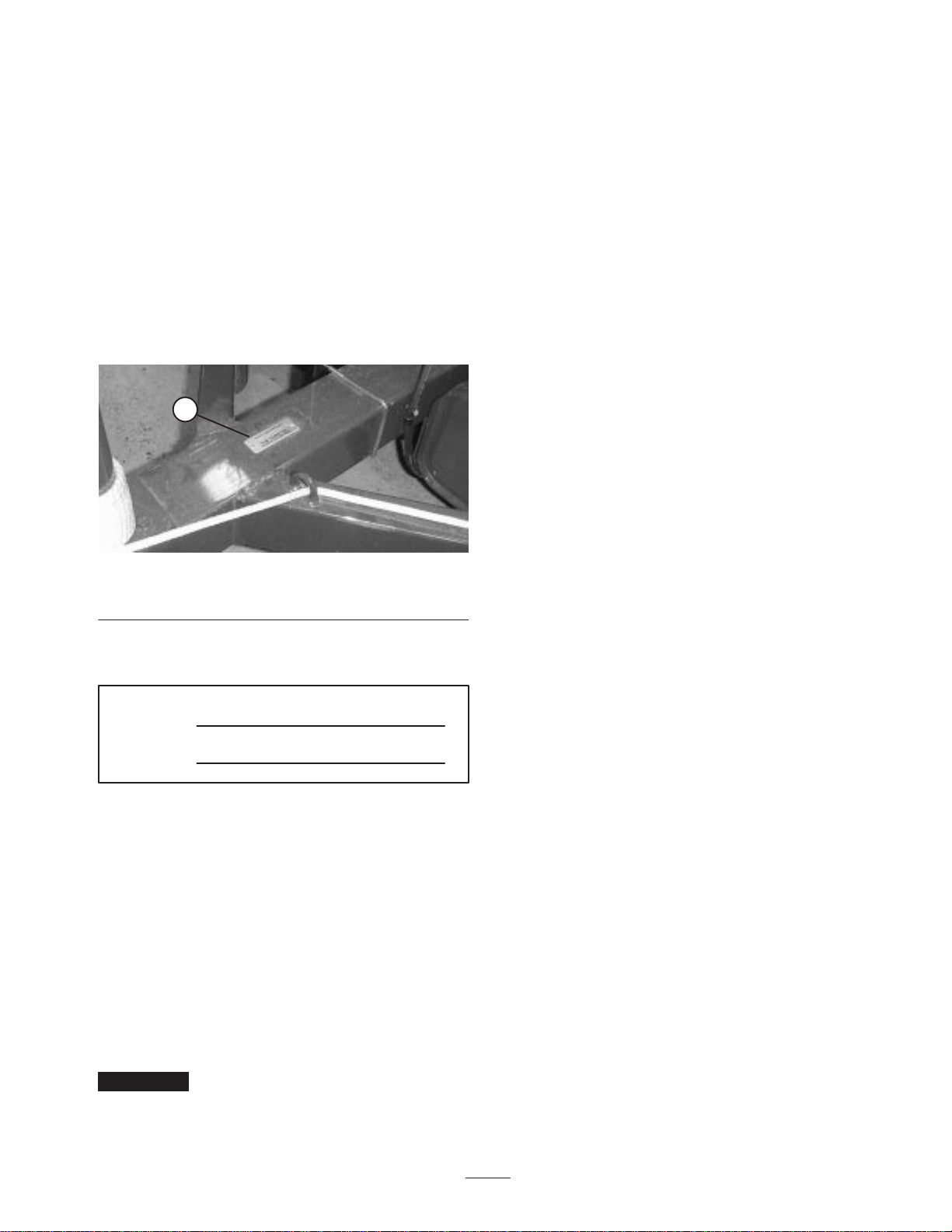
serial numbers of your product ready. Figure 1 illustrates
the location of the model and serial numbers on the
product.
1
Figure 1
1. Model & serial number plate
Write the product model and serial numbers in the space
below:
Model No.
Serial No.
This manual identifies potential hazards and has special
safety messages that help you and others avoid personal
injury and even death. Danger, Warning, and Caution are
signal words used to identify the level of hazard. However,
regardless of the hazard, be extremely careful.
Danger signals an extreme hazard that will cause serious
injury or death if you do not follow the recommended
precautions.
Warning signals a hazard that may cause serious injury or
death if you do not follow the recommended precautions.
Caution signals a hazard that may cause minor or moderate
injury if you do not follow the recommended precautions.
This manual uses two other words to highlight information.
Important calls attention to special mechanical
information and Note: emphasizes general information
worthy of special attention.
Safety
The RAKE–O–VAC was designed and tested to offer
safe service when operated and maintained properly.
Although hazard control and accident prevention
partially are dependent upon the design and
configuration of the machine, these factors are also
dependent upon the awareness, concern, and proper
training of the personnel involved in the operation,
transport, maintenance, and storage of the machine.
Improper use or maintenance of the machine can result
in injury or death. To reduce the potential for injury or
death, comply with the following safety instructions.
Since the Rake–O–Vac must be towed to operate, it is
extremely important that the tow tractor be carefully
selected to assure the best performance and safe operation.
The tow tractor must have the proper wheel base and tread
width and equipped with a roll bar and seat belt to operate
safely on hilly terrain. The normal operating speed is 6 mph
but will vary with terrain and debris being picked up. The
maximum transport speed is 20 mph with slower speeds
required on hilly terrain. Refer to tractor Operator’s Manual
for information or tractor service agency if you have any
question on safe operation.
The brakes of the tow tractor must have the capacity to stop
the Rake–O–Vac with hopper fully loaded and traveling at
the maximum recommended transport speed.
The power take–off drive of the Rake–O–Vac requires a
tractor with operating speeds of 540 rpm and output power
of 20 hp or higher. Do not exceed the 540 rpm speed.
The Rake–O–Vac must comply with local road
requirements, if transported on public roads. A
Slow–moving vehicle sign has been provided. Signal lights
and brakes are not provided and may be required in some
areas.
Before Operating
•Operate the machine only after reading and
understanding the contents of this manual. A
replacement manual is available by sending complete
model and serial number to:
The Toro Company
8111 Lyndale Avenue South
Bloomington, Minnesota 55420–1196.
•Never allow children to operate the machine or adults to
operate it without proper instructions.
•Become familiar with the controls and know how to
stop the engine/sweeper quickly.
•Keep all shields, safety devices and decals in place. If a
shield, safety device or decal is malfunctioning,
illegible, or damaged, repair or replace it before
operating the machine.

4
•Always wear substantial shoes. Do not operate machine
while wearing sandals, tennis shoes or sneakers. Do not
wear loose fitting clothing which could get caught in
moving parts and cause personal injury.
•Wearing safety glasses, safety shoes, long pants and a
helmet is advisable and required by some local safety
and insurance regulations.
•Keep everyone, especially children and pets away from
the areas of operation.
•Since gasoline is highly flammable, handle it carefully.
– Use an approved gasoline container.
– Do not remove cap from fuel tank when engine is
hot or running.
– Do not smoke while handling gasoline.
– Fill fuel tank outdoors and to about one inch below
top of tank, (bottom of filler neck). Do not overfill.
– Wipe up any spilled gasoline.
While Operating
•Exhaust fumes are hazardous and could be deadly, so do
not run the engine in a confined area without adequate
ventilation.
•This product may exceed noise levels of 85 dB(A) at
the operator position. Ear protectors are recommended,
for prolonged exposure, to reduce the potential of
permanent hearing damage.
•Never carry passengers on prime mover or allow
anyone to ride on sweeper.
•Disengage clutch before starting sweeper engine.
•Using the machine demands attention. To prevent
tipping or loss of control:
– Use extreme caution around ditches, creeks or other
hazards.
– Watch for holes or other hidden hazards.
– Use caution when operating machine on a steep
slope. Reduce speed when making sharp turns or
when turning on hillsides.
– Avoid sudden stops and starts.
– Before backing up, look to the rear and assure no
one is behind the machine.
– Watch out for traffic when near or crossing roads.
Always yield the right of way.
•Before leaving operator position:
– Shift into neutral, stop prime mover and engage
parking brake.
– Shut engine off and wait for all movement to stop.
The impeller may momentarily turn after other
components have stopped. Use extreme caution
when removing cover from blower housing.
– Disengage and lower sweeper implement.
– Shut sweeper engine off.
– Disengage P.T.O.
– Take precautions to prevent accidental starts, rolling
away, etc.
•Do not step over P.T.O. shaft to get to other side of
machine. Walk around sweeper.
•Never get on or off prime mover with P.T.O. shaft
engaged.
•If prime mover or sweeper ever vibrate abnormally,
stop immediately, turn engine off, wait for all motion to
stop and inspect for damage. Repair all damage before
commencing operation.
•Whenever machine is left unattended, be sure engine is
stopped, implement is lowered and key is removed from
ignition switch.
•Shut sweeper blower off when dumping contents of
hopper. Always stand to extreme right or left side of
hopper when opening tailgate.
•Park on a level surface, empty hopper and block wheels
before removing sweeper from prime mover.
Maintenance
•Disengage power to sweeper implement and stop engine
before servicing or making adjustments.
•Disengage power to sweeper implement and stop engine
when transporting or not in use.
•To make sure entire machine is in good condition, keep
all nuts, bolts and screws properly tightened.
•If major repairs are ever needed or assistance is
required, contact an Authorized TORO Distributor.
•To reduce potential fire hazard, keep the engine area
free of excessive grease, grass, leaves and accumulation
of dirt.
•If the engine must be running to perform a maintenance
adjustment, keep hands, feet, clothing, and any parts of
the body away from the engine and any moving parts.
Keep everyone away.
•Do not overspeed engine by changing governor settings.
To assure safety and accuracy, have an Authorized Toro
Distributor check maximum engine speed with a
tachometer. P.T.O. driven machines must not exceed
540 R.P.M.

5
•Engine must be shut off before checking oil or adding
oil to the crankcase.
•Check prime mover brakes periodically to be sure
brakes, when applied, will hold firmly. Also, check to
make sure all safety equipment is functioning properly.
•To be sure of optimum performance and safety, always
purchase genuine TORO replacement parts and
accessories. Replacement parts and accessories made by
other manufacturers could be dangerous. Such use
could void the product warranty of The Toro Company.
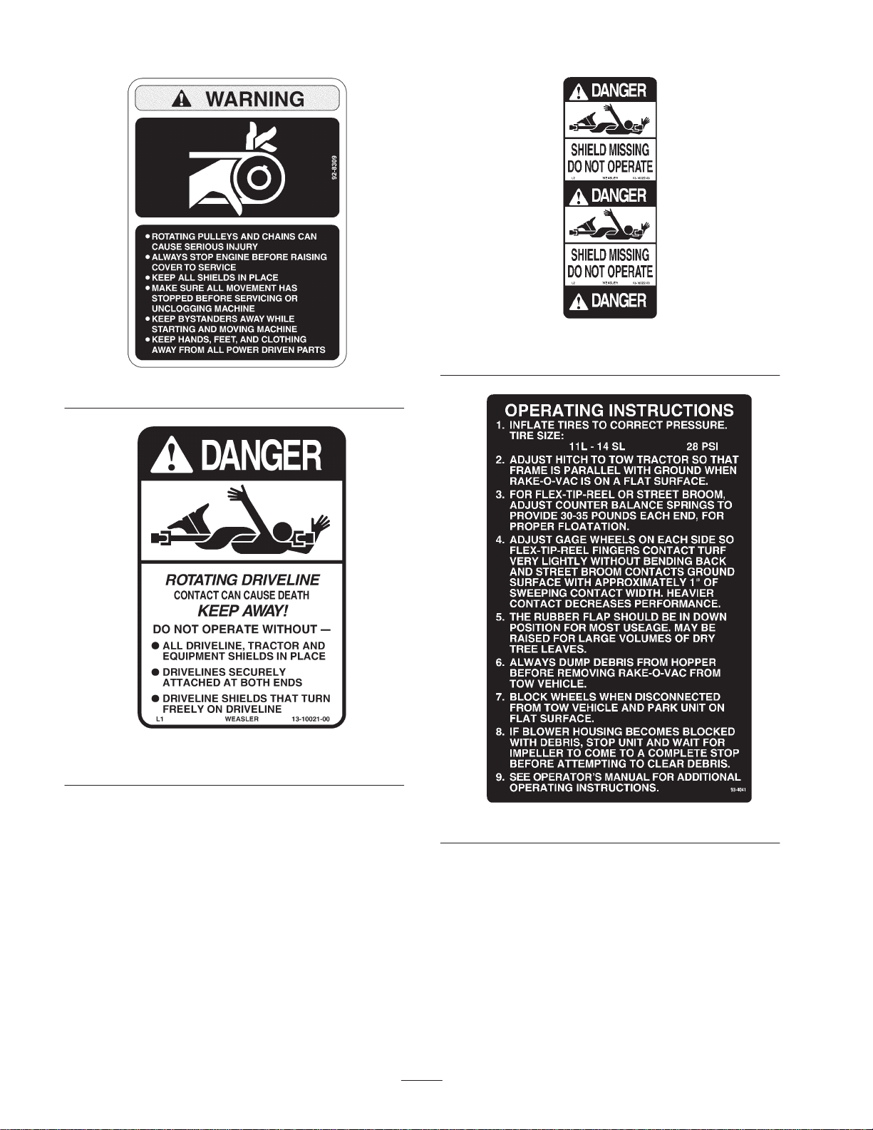
Safety and Instruction Decals
Safety decals and instructions are easily visible to the operator and are located near any area
of potential danger. Replace any decal that is damaged or lost.
67-5360
13-7430
13-2930
1. Slow moving vehicle
13-6760
13-6410
61-5950
53-4420
93-7307
6
92-8309
92-1581
(Model 07052)
92-1582
(Model 07052)
93-4041

7
Specifications
Note: Specifications and design are subject to change without notice.
Machine Drive (Model 07050): Kohler, 4 cycle air cooled 22 H.P. engine @ 3600 rpm, 41.1 cu. in.
(674 cc) displacement. Oil capacity is 4 pints w/filter. Mechanical fuel pump. Gas
tank capacity is 4 gallons.
(Model 07052): Powered by Power Take Off drive from prime mover–540 RPM.
Frame All welded structural rectangular 11 ga. tubing.
Hitch (Model 07050) Pin–type, 3/4” dia. vertically adjustable in 1” increments.
Hitch (Model 07052) Pin–type, 3/4” dia. three vertical positions for tractor hitches ranging from 7–1/4” to
17–1/4” in height.
Fan
Centrifugal type–double inlet; 4 blade, 16” wide, 23–14” diameter, 3/16” thick, high
tensile steel. Shaft mounted in self–aligning, sealed ball bearings. Blower inlet area
is 286 sq. in., blower discharge area is 255 sq. in. Twin fan hood construction for
uniform air distribution: 4–1/2” deep x 63” wide (inlet area–283 sq. in.); variable
position from weighted rubber flap.
Fan Drive (Model 07050) Banded double drive belt direct from drive shaft to fan impeller drive shaft with
driver pulley, fan with driven pulley. Fan impeller runs at 1580 R.P.M. (tip speed
9100 ft./min.) at 3250 engine R.P.M.
Fan Drive (Model 07052) Banded double drive belt direct from drive shaft to fan impeller drive shaft with
driver pulley, fan with driven pulley. Fan impeller runs at 1490 R.P.M. (tip speed
9100 ft./min.) with 540 PTO R.P.M.
Hopper 5–3/4 cu. yd. volume; 18 gauge top section with 16 gauge bottom section–rib
reinforced; full width self cleaning semi–automatic dumping.
Flex Tip Reel
Forward spinning with 6 rows of teeth. All steel construction with replaceable nylon
teeth; each row containing 11 individually spring–loaded flexible sets, 552 teeth
total; shaft set in self–aligning sealed bearings. Reel supported by adjustable
counter balance springs and adjustable gauge wheels. Gauge wheels are steel
construction with non–scuffing rubber tires and sealed ball bearings; infinitely
adjustable vertically.
Flex Tip Reel Drive
(Model 07050) Banded double drive belt from engine pulley to jackshaft pulley; belt from jack shaft
(driver) pulley to flex tip reel (driven) pulley. Flex tip runs at 275 R.P.M. (tip speed
1355 ft./min.) at 3250 engine R.P.M.
Flex Tip Reel Drive
(Model 07052) #60 roller chain from 40 tooth side shaft sprocket to 29 tooth jackshaft sprocket.
Belt jack shaft (driver) pulley flex tip reel (driven) pulley. Flex tip runs at 260 R.P.M.
(tip speed 1,230 ft./min.) with 540 R.P.M.
Dimensions and Weights
(approx.)
Width 85–1/2”
Height 79–1/2”
Length 13’ 3” (Model 07050)
14’ (Model 07052)
Empty Weight 2160 lb. (Model 07050)
1980 lb. (Model 07052)
Optional Equipment
Hard Surface Brush Kit Model No. 07162
Thatching Reel Kit Model No. 07178
Flex Tip Reel Model No. 07164
Spark Arrester Muffler*Kohler No 1218902
*Contact Your Local Kohler Dealer

8
Setup
Note: Determine the left and right side of the machine from the normal operating position.
Description Qty. Use
Clutch Adjusting Plates
Bolt
Nut
2
4
4Use to torque clutch
Operator’s Manual
Engine Operator’s Manual 1
1Read before operating the machine.
Parts Catalog 1
Registration Card 1Fill out and return to Toro.
Remove, Activate And Charge
Battery
(Model 07050 only)
1. If Battery is not filled with electrolyte or activated, bulk
electrolyte with 1.260 specific gravity must be
purchased from a local battery supply outlet and added
to battery.
Danger
Battery electrolyte contains sulfuric acid which is a
deadly poison and causes severe burns.
•Do not drink electrolyte and avoid contact with
skin, eyes or clothing. Wear safety glasses to
shield your eyes and rubber gloves to protect
your hands.
•Fill the battery where clean water is always
available for flushing the skin.
CALIFORNIA
Proposition 65 Warning
Battery posts, terminals, and related accessories
contain lead and lead compounds, chemicals
known to the State of California to cause cancer
and reproductive harm. Wash hands after
handling.
Warning
2. When battery is charged, disconnect charger from
electrical outlet and battery posts. Allow battery to sit
for 5 to 10 minutes before proceeding to next step.
3. Unhook springs from battery cover, remove cover and
lift battery out of battery box.
4. Remove filler caps from battery and slowly fill each
cell until electrolyte is up to fill line.
5. Replace filler caps and connect a 3 to 4 amp battery
charger to the battery posts. Charge the battery at a rate
of 3 to 4 amperes for 4 to 8 hours.
Charging the battery produces gasses that can
explode.
Never smoke near the battery and keep sparks and
flames away from battery.
Warning
6. Remove filler caps and slowly add electrolyte to each
cell until level is up fill line. Install filler caps.
Important Do not overfill battery. Electrolyte will
overflow onto other parts of the machine and severe
corrosion and deterioration will result.
Install Battery
(Model 07050 only)
1. Slide the battery into battery box with the terminals to
the inside.

9
Battery terminals or metal tools could short
against metal tractor components causing sparks.
Sparks can cause the battery gasses to explode,
resulting in personal injury.
•When removing or installing the battery, do not
allow the battery terminals to touch any metal
parts of the tractor.
•Do not allow metal tools to short between the
battery terminals and metal parts of the tractor.
Warning
2. Attach the negative cable (wire from engine block) to
the negative (–) terminal of the battery.
Incorrect battery cable routing could damage the
tractor and cables causing sparks. Sparks can
cause the battery gasses to explode, resulting in
personal injury.
•Always disconnect the negative (black) battery
cable before disconnecting the positive (red)
cable.
•Always connect the positive (red) battery cable
before connecting the negative (black) cable.
Warning
3. Attach the positive cable (wire from ignition switch) to
the positive (+) terminal.
4. Coat the terminals and mounting fasteners with
petroleum jelly to prevent corrosion.
5. Install battery cover and secure with springs.
Mount Sweeper To Prime
Mover
To assure proper debris pickup, make sure sweeper frame is
parallel with the ground.
1. Position sweeper on a flat, level surface.
2. Insert sweeper jack caster wheel onto sweeper end of
jack tube.
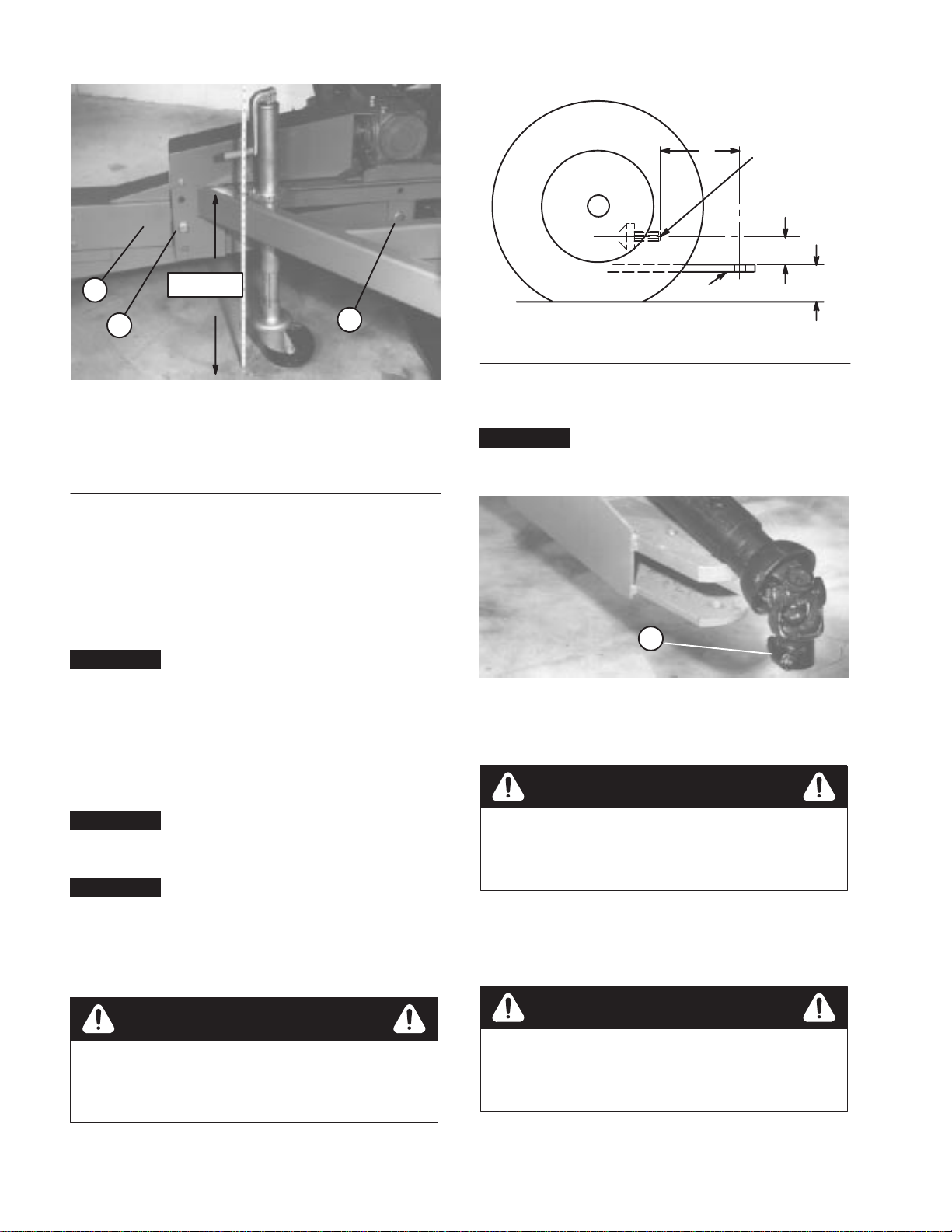
3. Adjust sweeper jack so distance from top of frame to
ground is approximately 23–1/2” (Fig. 2).
4. Back prime mover up to sweeper.
5. Adjust sweeper hitch tongue to same level as hitch of
prime mover as follows:
Model 07050
•Remove capscrews and locknuts securing hitch tongue
to frame (Fig. 2).
•Raise or lower hitch tongue to position approximately
level with prime move hitch and secure with (2)
capscrews and locknuts.
1
2
23–1/2”
3
Figure 2
1. Sweeper jack
2. Hitch tongue
(Model 07050)
3. Adjusting screws
Model 07052
•Remove front and rear capscrews and locknuts securing
hitch tongue to frame (Fig. 3).
•Raise or lower hitch tongue to position it approximately
level with prime move hitch and secure with (2)
capscrews and locknuts. The main frame should be
parallel with the ground surface about 23–1/2” when
attached to tractor.
10
23–1/2”
1
23
Figure 3
1. Hitch tongue
(Model 07052)
2. Front adjustment
capscrew
3. Rear adjustment
capscrew
6. Secure sweeper hitch tongue to prime mover hitch with
hitch pin and hair pin cotter.
7. Raise sweeper jack caster wheel tube up to frame and
fold handle down.
8. Store caster wheel in compartment on left side of
machine in front of hopper.
Important After first ten hours of operation, re–tighten
capscrews and locknuts securing hitch tongue to sweeper.
Connecting Drive Shaft to
Prime Mover PTO Shaft
(Model 07052 only)
Important Mating tractor must have the dimensions
shown in figure 4. Do not operate sweeper with tractor of
different dimensions.
Important The distance (“A” Figure 4) between the
hole in the tractor hitch and the point where the drive shaft
coupler attaches to the prime mover, P.T.O. shaft must be
14’’ plus or minus 1/2”. If 14” is not attained, an
adjustment to the tractor hitch must be made before
operating sweeper.
If ”B” dimension (Fig. 4) is less than 3”, extreme
caution must be used when tractor and sweeper
unit crests tops of steep hills.
Warning
A = 13–1/2” TO 14–l/2”
B = 2–3/4” TO 11–1/2’’
C = 7–1/4” TO 17–1/4”
P.T.O. SHAFT
(540 RPM)
A
B
C
DRAW BAR
Figure 4
1. Attach drive shaft quick disconnect to P.T.O. shaft of
prime mover.
Important A shield should be provided on tractor to
cover drive shaft universal joint. Do not operate drive shaft
without this shield in place.
1
Figure 5
1. Drive shaft quick coupler
This sweeper is designed for a 540 RPM P.T.O.
shaft only. Do not operate with a 1000 RPM P.T.O.
tractor.
Warning
Removing Sweeper From
Prime Mover
Always empty sweeper hopper before
disconnecting hopper from prime mover or
sweeper may tip backwards and cause injury.
Warning
1. Park sweeper on a level surface and block wheels.
11
2. On Model 07052 only, disconnect drive shaft quick
coupler from prime mover PTO shaft.
3. Insert castor wheel onto jack tube.
4. Raise sweeper jack handle and lower caster wheel to
ground.
5. Continue to raise sweeper with jack until hair pin cotter
and hitch pin can be removed from hitch.
Before Operating
Before servicing or making adjustments to the
machine, stop engine(s), disengage clutch and
disconnect PTO (If so equipped) from prime
mover.
Caution
Check Engine Oil
(Model 07050 only)
The engine is shipped with approximately 2 quarts
(w/filter) of oil in the crankcase; however, level of oil must
be checked before and after the engine is first started.
1. Position machine on a level surface.
2. Remove dipstick and wipe it with a clean rag. Insert
dipstick into tube and make sure it is seated fully.
Remove dipstick from tube and check level of oil. If oil
level is low, remove filler cap and add enough oil to
raise level to “FULL” mark on dipstick.
1
Figure 6
1. Dipstick
1
Figure 7
1. Filler cap
3. The engine uses any high-quality detergent oil having
the American Petroleum Institute -API- “service
classification” SG, SH or SJ. Oil viscosity (weight) is
selected according to the anticipated ambient
temperature.
Temperature / viscosity recommendations are:
•Above 0F (–20C) – Use 10W–30 or 10W–40.
•Below 32F (0C) – Use 5W–20 or 5W–30.
4. Pour oil into fill opening until the oil level is up to the
“FULL” mark on the dipstick. Add the oil slowly and
check the level often during this process. DO NOT
OVERFILL
Important Check level of oil every 8 operating hours
or daily. Initially, change oil after the first 5 hours of
operation; thereafter, under normal conditions, change oil
every 100 hours and filter every 200 hours. However,
change oil more frequently when engine is operated in
extremely dusty or dirty conditions.
5. Install the dipstick firmly in place.
Check Clutch Housing Oil
(Model 07050 only)
The clutch housing uses any high-quality detergent oil
having the American Petroleum Institute -API- “service
classification” SE, SF, SG or SH. Recommended viscosity
(weight) is SAE 30.
1. Position machine on a level surface.
2. Remove oil level plug on side of clutch housing.
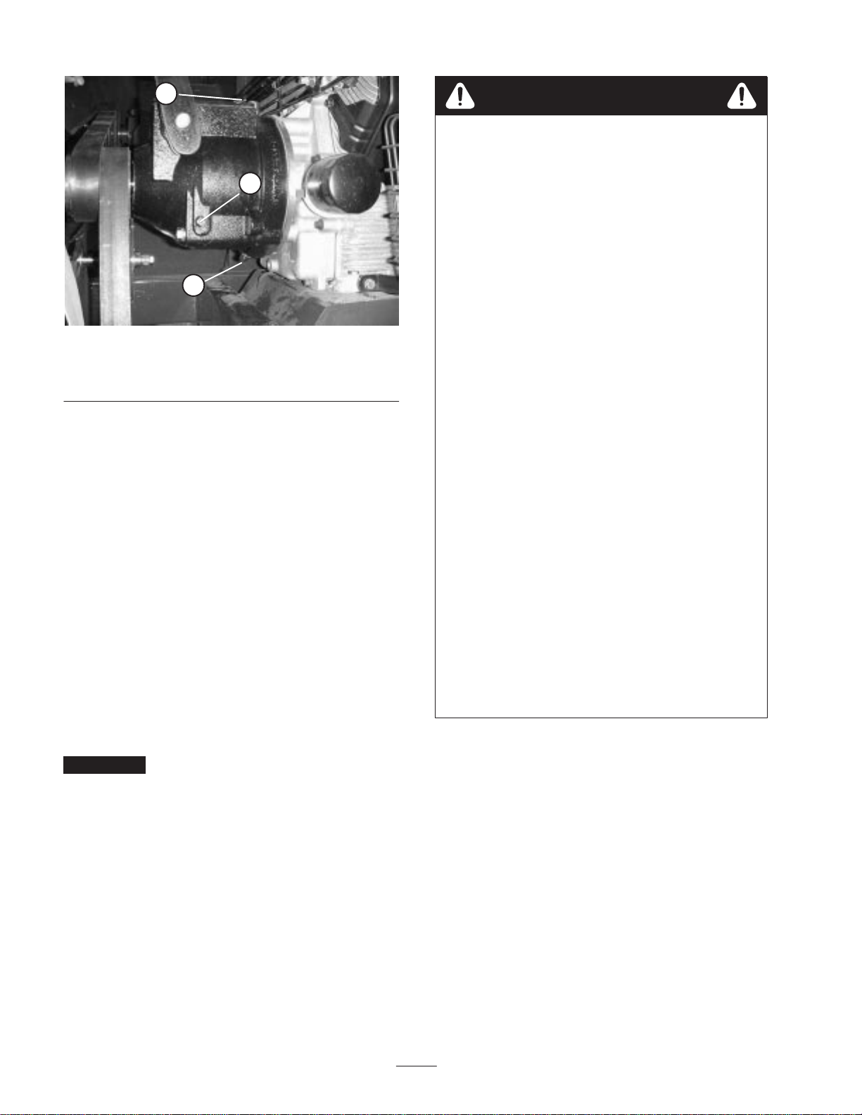
12
1
2
3
Figure 8
1. Oil level plug
2. Filler/breather plug 3. Drain plug
3. If oil drips from hole, there is enough oil in clutch
housing. Replace plug.
4. If oil does not drip from hole, oil must be added to
clutch housing. Do not replace plug.
5. Remove filler plug from top of clutch housing.
6. Add enough oil to clutch housing until it drips out oil
level hole.
7. Reinstall plugs.
Fill Fuel Tank
(Model 07050 only)
Fuel tank capacity is approximately 4 gallons.
Use unleaded regular gasoline suitable for automotive use
(85 pump octane minimum). Leaded regular gasoline may
be used if unleaded regular is not available.
Important Never use methanol, gasoline containing
methanol, or gasohol containing more than 10% ethanol
because the fuel system could be damaged. Do not mix oil
with gasoline.
1. Clean area around fuel tank cap.
2. Remove fuel tank cap.
3. Fill tank to about one inch below top of tank, (bottom of
filler neck). DO NOT OVERFILL. Then install cap.
4. Wipe up any fuel that may have spilled to prevent a fire
hazard.
Danger
In certain conditions, gasoline is extremely
flammable and highly explosive. A fire or
explosion from gasoline can burn you and others
and can damage property.
•Fill the fuel tank outdoors, in an open area,
when the engine is cold. Wipe up any gasoline
that spills.
•Do not fill the fuel tank completely full. Add
gasoline to the fuel tank until the level is 1 in.
(25 mm) below the bottom of the filler neck.
This empty space in the tank allows gasoline to
expand.
•Never smoke when handling gasoline, and stay
away from an open flame or where gasoline
fumes may be ignited by a spark.
•Store gasoline in an approved container and
keep it out of the reach of children. Never buy
more than a 30-day supply of gasoline.
•Always place gasoline containers on the ground
away from your vehicle before filling.
•Do not fill gasoline containers inside a vehicle or
on a truck or trailer bed because interior
carpets or plastic truck bed liners may insulate
the container and slow the loss of any static
charge.
•When practical, remove gas-powered equipment
from the truck or trailer and refuel the
equipment with its wheels on the ground.
•If this is not possible, then refuel such
equipment on a truck or trailer from a portable
container, rather than from a gasoline dispenser
nozzle.
•If a gasoline dispenser nozzle must be used, keep
the nozzle in contact with the rim of the fuel
tank or container opening at all times until
fueling is complete.
Check Tire Pressure
Check tire pressure daily to assure proper level.
Correct tire pressure is 28 psi.

13
Transport Hooks
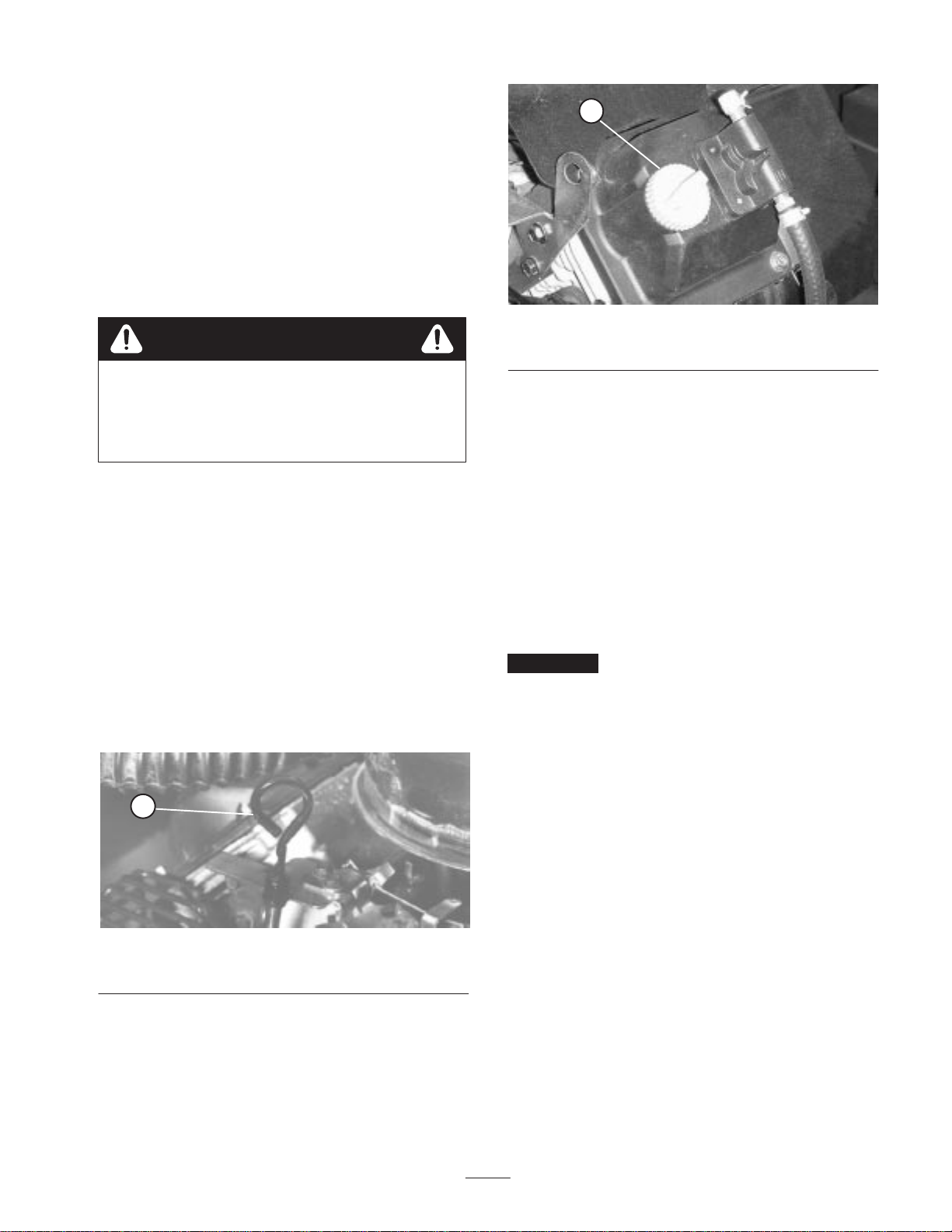
1. Lift each end of reel and remove transport hooks before
operating machine.
1
Figure 9
1. Transport hook
2. When transporting sweeper from one location to
another, support flex tip reel, broom or thatching reel.
with transport hooks.
Adjust Reel Support Arm
When machine is operated, gauge wheel should ride over
the turf evenly. If reel support arm has a tendency to
bounce, spring setting is too tight. If gauge wheel scars turf,
spring setting is too light.
To adjust reel support arm:
1. Pull rake lever rearward to lower flex tip reel or broom.
1
2
3
Figure 10
1. Spring scale
2. Counterbalance spring 3. Adjustment screw
2. Position a spring scale on transport hook and lift up.
Tension necessary to lift gauge wheel off ground should
be 30–50 lbs.
3. If tension is not 30–50 lbs., adjustment is made by
tightening or loosening adjustment screw on
counterbalance spring.
4. Perform this procedure on both sides of sweeper.
Note: Because of added weight of drive components, the
R.H. spring will require a tighter setting than the L.H.
spring.
Adjust Rake Depth
Flex tip reel should be adjusted so rake tips slightly touch
surface but do not penetrate turf. If rake tips penetrate turf,
improper debris pickup could result.
1. Position sweeper on a level surface.
2. Loosen locknut on depth adjustment bolt so it can be
turned.
1
Figure 11
1. Locknut
3. Turn depth adjustment bolt until rake slightly contacts
top of turf grass. If a broom is installed, slight contact
should be made with surface. When broom is operating,
the contact width surface should be about 1” wide
across entire length of broom.
1
Figure 12
1. Depth adjusting bolt

14
4. Repeat procedure on opposite side of machine.
5. Retighten adjustment lock nut.
Adjust Rubber Flap
For best debris pick up results, metal portion of front flap
should be vertical to ground.
1. Move flat lever forward to lower flat.
2
1
Figure 13
1. Rubber flap 2. Metal edge
2. Loosen jam nut on top of stop and rotate adjustment
bolt up or down until flap is vertical to ground.
2
1
Figure 14
1. Adjustment bolt 2. Stop
3. Tighten jam nut to secure adjustment.
Note: Flap may be positioned in raised position when
picking up large amounts of leaves.
Operation
Note: Determine the left and right sides of the machine
from the normal operating position.
Controls
Flap Lever
Move flap lever (Fig. 15) downward to engaged position
and upward for disengaged position. Move lever to upward
position when transporting machine.
Reel Lever
Push reel lever (Fig. 15) forward to raise flex tip reel. To
lower flex reel, push lever forward until catch releases, then
push to rear until lever hits STOP. Move lever to raised
position when sweeper is not in operation, when storing
machine or when transporting machine.
2
1
Figure 15
1. Flap lever 2. Reel lever
Clutch Handle
The clutch handle (Fig. 16) is located on the clutch
housing. Push outward on clutch handle to engage and
inward to disengage (Model 07050 only).
Important Move sweeper as quickly as possible after
lowering reel lever and engaging clutch lever to prevent
turf damage.
15
1
Figure 16
1. Clutch handle
Choke Control
To start a cold engine, close carburetor choke by moving
choke control lever (Fig. 17) to the “ON” position. After
engine starts, regulate choke to keep engine running
smoothly. As soon as possible, open the choke by moving
lever to the “OFF” position. Starting a warm engine
requires little or no choking (Model 07050 only).
1
23
Figure 17
1. Choke control
2. Ignition switch 3. Throttle control
Ignition Switch
The ignition switch (Fig. 17), which is used to start and
stop the engine, has three positions: OFF, RUN and
START. Rotate key clockwise — START position — to
engage starter motor. Release key when engine starts. The
key will move automatically to the ON position. To shut
engine off, rotate key counterclockwise to the OFF position
(Model 07050 only).
Throttle Control
Throttle (Fig. 17) is used to operate engine at various
speeds. Moving throttle lever to FAST position increases
engine speed. To decrease engine speed, move lever to
SLOW position (Model 07050 only).
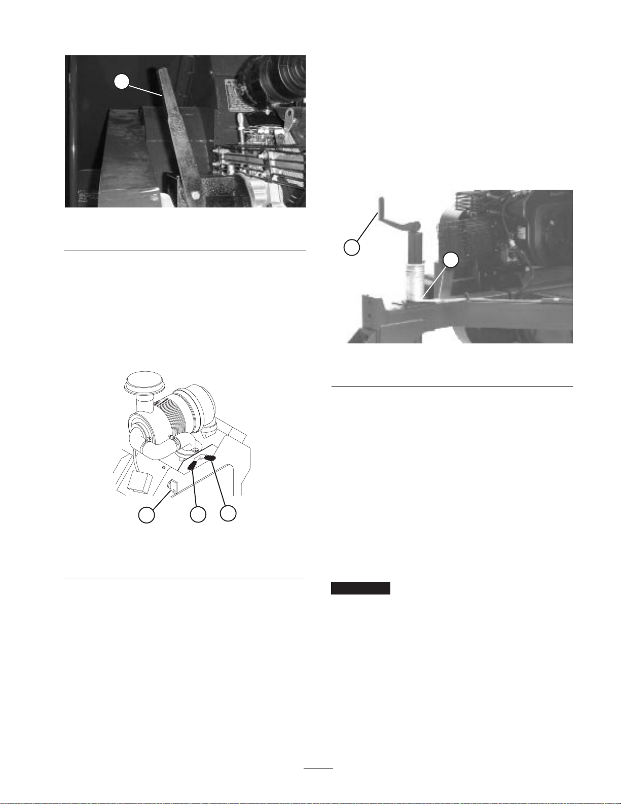
Tailgate Latch Rope
Pull tailgate latch rope (Fig. 18) to unlatch tailgate when
emptying hopper.
1
2
Figure 18
1. Tailgate latch rope 2. Jack handle
Starting Instructions
(Engine Driven)
1. Place all controls in disengaged or off position.
2. Move throttle lever midway between SLOW and FAST
position.
3. Move choke lever to ON position.
Note: Choke not required when starting a warm engine.
4. Insert key into ignition switch and rotate it clockwise to
start the engine. Release key when engine starts.
Regulate the choke to keep engine running smoothly.
Important To prevent overheating of the starter motor,
do not engage starter longer than 10 seconds. After 10
seconds of continuous cranking, wait 60 seconds before
engaging starter motor again.
5. Move throttle lever to desired engine speed.
6. Pull flap lever as far forward as possible.
7. Push rake lever to the rear as far as possible.
8. Engage rake by engaging clutch handle.
Note: Do not allow sweeper to stand still with rake
engaged as turf damage may occur.

16
Stopping Instructions
1. Disengage power to rake by disengaging clutch lever.
2. Move throttle lever to “SLOW” position.
3. Move ignition switch to “OFF” position. Remove key
from switch to prevent accidental starting.
Important To stop sweeper in an emergency, move
ignition switch to “OFF”position.
Starting Instructions
(PTO Driven)
1. Read and understand all operating procedures in tow
tractor operator’s manual. Contact tow tractor dealer or
manufacturer regarding any questions you have about
safety or operation.
2. Make sure all P.T.O. guards are installed and operating
properly.
3. Know how to stop tow tractor and sweeper in an
emergency.
4. Pull flap lever as far forward as possible.
5. Push rake lever to the rear as far as possible.
6. Engage rake by engaging clutch handle.
Note: Do not allow sweeper to stand still with rake
engaged as turf damage may occur.
Operating Tips
•Before starting to sweep, survey area to determine the
best direction to sweep.
Note: To maintain a straight line when sweeping, sight of
an object in the foreground.
•Always try to make a long, continuous run with a slight
overlap on the return run.
•On turf areas, the flex tip reel will pick up twigs,
clippings, leaves, pine needles and cones, small debris
(beverage cans, small bottles, paper plates, etc.).
•The rake teeth are made of flexible nylon and easily
changed. To prevent damage, the rake is protected from
solid obstructions by spring action. The nylon teeth will
not mar bronze, stone markers, sidewalks or pavement.
•Because of its unique design, the sweeper also grooms
the turf. The flex tip reel combs through and lifts grass
for a uniform cut when mowed. As it cleans, the light
scarifying action increase water and pesticide
penetration, thus reducing the need for renovation.
Important Do not make sharp turns when using the
thatching reel as damage to turf may occur.
Important Do not operate sweeper while reel is turning
and in the raised position. Damage to the rake and tires may
result if teeth come in contact with tires.
This product may exceed noise levels of 85 dB(A)
at the operator position. Ear protectors are
recommended, for prolonged exposure, to reduce
the potential of permanent hearing damage.
Caution
•To empty hopper, pull tailgate latch rope.
Inspection And Cleanup After
Operation
•When sweeping has been completed, thoroughly clean
and wash the machine. Air dry hopper. After cleaning, it
is recommended that the machine be inspected for
possible damage to mechanical components and blower.
These procedures will assure that the machine will
perform satisfactorily during next sweeping operation.
Important When towing sweeper for long distances,
fasten gauge wheel arm securely to sweeper frame with
transport hooks. Should gauge wheel arm fall to ground,
damage to sweeper may occur.

17
Maintenance
Note: Determine the left and right sides of the machine
from the normal operating position.
Important Refer to your engine operator’s manual for
additional maintenance procedures.
Lubrication
The Rake–O–Vac has grease fittings that must be lubricated
regularly with No. 2 General Purpose Lithium Base Grease.
Lubricate bearings after every 30 hours of operation or
whenever machine is washed with water. Bearings and
bushings must be lubricated daily when operating
conditions are extremely dusty and dirty. Dusty and dirty
operating conditions could cause dirt to get into the
bearings and bushings, resulting in accelerated wear. The
grease fittings that must be lubricated are the gauge wheel
bearings (2) (Fig. 19); reel shaft bearings (2) (Fig. 19);
impeller shaft bearings (2) (Fig. 20); Jackshaft bearings (2)
(Fig. 21) left and right trailing arms (1 ea.) (Fig. 21) front
and rear drive shafts (6) (Model 07052 only)
(Fig. 22 & 23).
1. Wipe grease fittings clean so foreign matter cannot be
forced into the bearing or bushing.
2. Pump grease into the bearing or bushing.
3. Wipe up excess grease.
Figure 19
Figure 20
Figure 21
To lubricate drive shafts:
1. Disconnect sweeper from P.T.O. shaft on prime mover.
2. Rotate shafts by hand until you can see the grease
fittings through the three holes in sides of shields.
Figure 22

18
Figure 23
Oil Drive Chain
(Model 07052)
Oil entire length of all chains every 30 hours of operation
with SAE 30 oil.
Figure 24
Oil Sweeper Jack
Sweeper jack must be oiled after every 50 hours of
operation.
Figure 25
Changing Engine Oil and Filter
(Model 07050 only)
Change oil initially after the first 5 hours of operation,
thereafter change oil every 100 hours and filter every 200
hours.
1. Park the machine on a level surface and turn the engine
off.
2. Remove drain plug and let oil flow into drain pan.
When oil stops, install drain plug.
Note: Warm oil flows better and carries more contaminants
than cold oil.
3. Remove oil filter. Apply a light coat of clean oil to the
new filter gasket.
1
2
Figure 26
1. Drain plug 2. Oil filter
4. Screw filter on by hand until gasket contacts mounting
plate, then tighten 1/2 turn further. DO NOT
OVER–TIGHTEN.
5. Add oil to crankcase, refer to Check Engine Oil.
6. Dispose of used oil properly.
19
General Air Cleaner
Maintenance
(Model 07050 only)
•Check air cleaner body for damage which could
possibly cause an air leak. Replace a damaged air
cleaner body.
•Service the air cleaner filters every 400 hours (more
frequently in extreme dusty or dirty conditions). Do not
over service air filter.
•Be sure cover is sealing around air cleaner body.
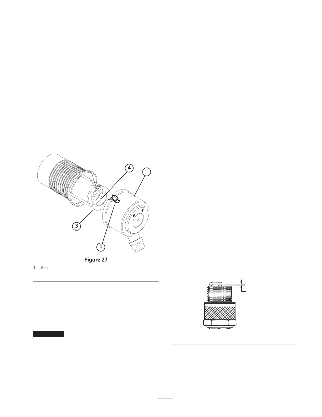
Servicing Air Cleaner
1. Release latches securing air cleaner cover to air cleaner
body. Separate cover from body. Clean inside of air
cleaner cover.
2
ÎÎ
ÎÎ
ÎÎÎ
ÎÎÎ
ÎÎÎ
ÎÎ
ÎÎ
ÎÎ
1
3
4
Figure 27
1. Air cleaner latches
2. Dust cup 3. Primary filter
4. Safety filter
2. Gently slide primary filter out of air cleaner body to
reduce the amount of dust dislodged. Avoid knocking
filter against air cleaner body. Do not remove safety
filter.
3. Inspect primary filter and discard if damaged. Do not
wash or reuse a damaged filter.
Important Never attempt to clean a safety filter.
Replace the safety filter with a new one after every
three primary filter services.
4. Blow compressed air from inside to the outside of dry
filter element. Do not exceed 100 psi to prevent damage
to the element.
5. Keep air hose nozzle at least 2” from filter and move
nozzle up and down while rotating the filter element.
Inspect for holes and tears by looking through the filter
toward a bright light.
6. Inspect new filter for shipping damage. Check sealing
end of filter. Do not install a damaged filter.
7. Insert new filter properly into air cleaner body. Make
sure filter is sealed properly by applying pressure to
outer rim of filter when installing. Do not press on
flexible center of filter.
8. Reinstall cover and secure latches. Make sure cover is
positioned with TOP side up.
Replacing Spark Plugs
(Model 07050 only)
Replace spark plugs or reset gap after every 200 operating
hours to assure proper engine performance and reduce
exhaust emission level.
Correct spark plug to use is a Champion RC 12YC or
equivalent.
Recommended air gap is .040”.
Note: The spark plug usually lasts a long time; however,
the plug should be removed and checked whenever the
engine malfunctions.
1. Clean area around spark plugs so foreign matter cannot
fall into cylinder when spark plug is removed.
2. Pull spark plug wires off spark plugs and remove plugs
from cylinder head.
3. Check condition of side electrode, center electrode, and
center electrode insulator to assure there is no damage.
.040”
Figure 28

20
Important A cracked, fouled, dirty or otherwise
malfunctioning spark plug must be replaced. Do not sand
blast, scrape, or clean electrodes by using a wire brush
because grit may eventually release from the plug and fall
into the cylinder. The result is usually a damaged engine.
Removing Debris From Engine
(Model 07050 only)
To ensure proper cooling, make sure the grass screen,
cooling fins and other external surfaces of the engine are
kept clean at all times.
Every 100 hours of operation (more often under extremely
dusty, dirty conditions) remove the blower housing and
other cooling shrouds and clean the cooling fins and
external surfaces as necessary. Make sure cooling shrouds
are reinstalled.
Note: Operating the engine with a blocked grass screen,
dirty or plugged cooling fins or cooling shrouds removed,
will cause engine damage due to overheating.
Replace Fuel Filter
(Model 07050 only)
Replace fuel filter after every 600 hours of operation.
1. Place a clean container under fuel filter.
2. Remove clamps securing fuel filter to fuel lines.
1
Figure 29
1. Fuel filter
3. Install new fuel filter to fuel lines with clamps
previously removed. Filter to be mounted so arrow
points toward carburetor.
Changing Clutch Housing Oil
(Model 07050 only)
Clutch housing oil should be changed annually, or every
800 hours of operation, whichever comes first.
1. Place a drain pan under drain plug at bottom of housing.
2. Remove drain plug at bottom of housing and remove
filler plug.
Note: Warm oil flows better and carries more contaminants
than cold oil.
3. Allow all oil to drain out.
4. Replace drain plug.
5. Remove filler/breather plug from top of clutch housing.
6. Remove oil level plug on side of clutch housing.
7. Add enough oil to clutch housing until it drips out
overflow hole.
1
2
3
Figure 30
1. Oil level plug
2. Filler/breather plug 3. Drain plug
8. Reinstall plugs.
Adjusting Clutch
(Model 07050 only)
If clutch slips, an adjustment is required. A properly
adjusted clutch will require 45–50 pounds of force applied
to clutch lever, 12 inches above clutch lever pivot shaft.
To check clutch adjustment proceed as follows:
1. Loosely assembly clutch adjusting plates together with
(4) bolts and nuts (Fig. 31).
This manual suits for next models
1
Table of contents
Other Toro Lawn Sweeper manuals


