SPECIFICATIONS & MAINTENANCE
2-3
Toro Single Stage Snow Service Manual
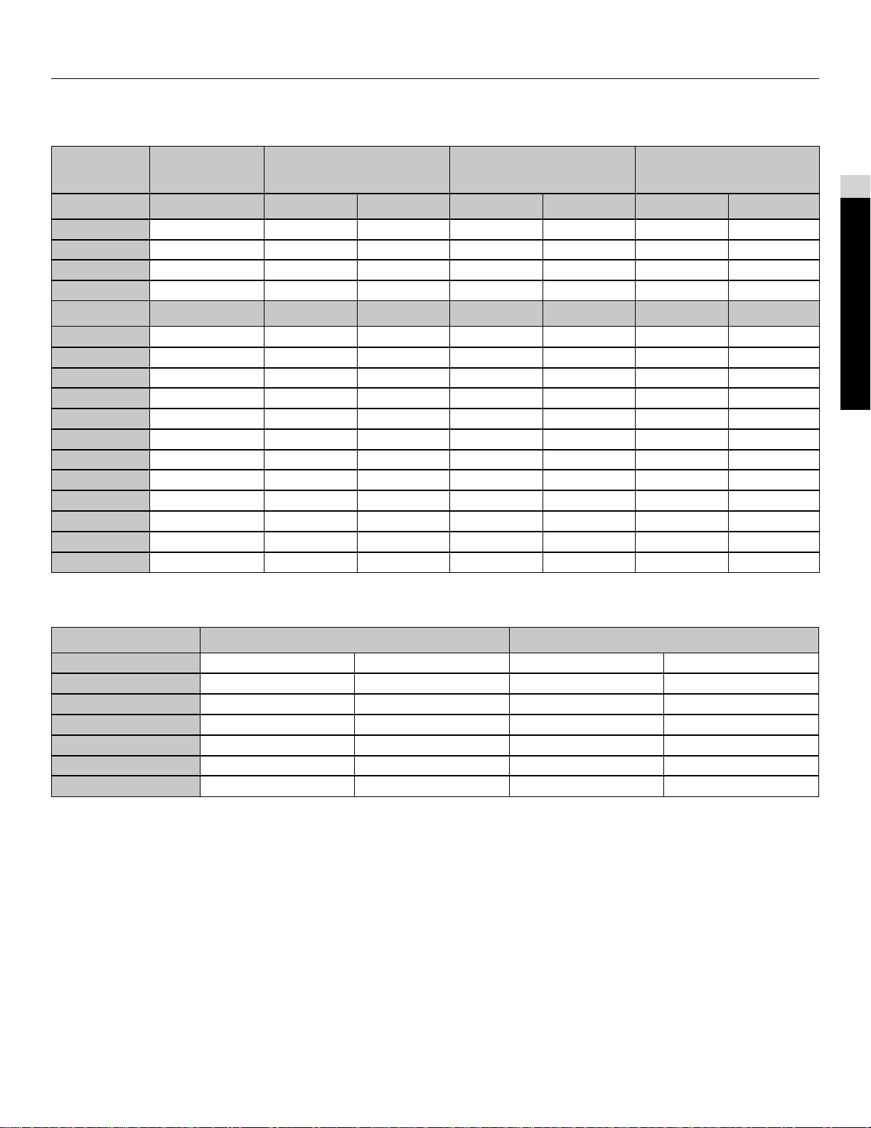
Standard Torque Values (Inch)
Thread Size
Grade 1, 5, & 8
with Thin Height
Nuts
SAE Grade 1 Bolts SAE Grade 5 Bolts SAE Grade 8 Bolts
In-lb In-lb N-cm In-lb N-cm In-lb N-cm
1/4-20 UNC 48 ± 7 53 ± 7 599 ± 79 100 ± 10 1125 ± 100 140 ± 15 1580 ± 170
1/4-28 UNF 53 ± 7 65 ± 10 734 ± 113 115 ± 10 1300 ± 100 160 ± 15 1800 ± 170
5/16-18 UNC 115 ± 15 105 ± 15 1186 ± 169 200 ± 25 2250 ± 280 300 ± 30 3390 ± 340
5/16-24 UNF 138 ± 17 128 ± 17 1446 ± 192 225 ± 25 2540 ± 280 325 ± 30 3670 ± 340
ft-lb ft-lb N-m ft-lb N-m ft-lb N-m
3/8-16 UNC 16 ± 2 16 ± 2 22 ± 3 30 ± 3 41 ± 4 43 ± 4 58 ± 5
3/8-24 UNF 17 ± 2 18 ± 2 24 ± 3 35 ± 3 47 ± 4 50 ± 4 68 ± 5
7/16-14 UNC 27 ± 3 27 ± 3 37 ± 4 50 ± 5 68 ± 7 70 ± 7 68 ± 9
7/16-20 UNF 29 ± 3 29 ± 3 39 ± 4 55 ± 5 75 ± 7 77 ± 7 104 ± 9
1/2-13 UNC 30 ± 3 48 ± 7 65 ± 9 75 ± 8 102 ± 11 105 ± 10 142 ± 14
1/2-20 UNF 32 ± 3 53 ± 7 72 ± 9 85 ± 8 115 ± 11 120 ± 10 163 ± 14
5/8-11 UNC 65 ± 10 88 ± 12 119 ± 16 150 ± 15 203 ± 20 210 ± 20 285 ± 27
5/8-18 UNF 75 ± 10 95 ± 15 129 ± 20 170 ± 15 230 ± 20 240 ± 20 325 ± 27
3/4-10 UNC 93 ± 12 140 ± 20 190 ± 27 265 ± 25 359 ± 34 374 ± 35 508 ± 47
3/4-16 UNF 115 ± 15 165 ± 25 224 ± 34 300 ± 25 407 ± 34 420 ± 35 569 ± 47
7/8-9 UNC 140 ± 20 225 ± 25 305 ± 34 430 ± 45 583 ± 61 600 ± 60 813 ± 81
7/8-14 UNF 155 ± 25 260 ± 30 353 ± 41 475 ± 45 644 ± 61 660 ± 60 895 ± 81
Standard Torque Values (Metric Fasteners)
Thread Size Class 8.8 Bolts Class 10.9 Bolts
M5 X 0.8 57 ± 5 inlb 644 ± 68 Ncm 78 ± 8 inlb 881 ± 90 Ncm
M6 X 1.0 96 ± 10 inlb 1085 ± 113 Ncm 133 ± 14 inlb 1503 ± 158 Ncm
M8 X 1.25 19 ± 2 ftlb 26 ± 3 Nm 28 ± 3 ftlb 38 ± 4 Nm
M10 X 1.5 38 ± 4 ftlb 52 ± 5 Nm 54 ± 6 ftlb 73 ± 8 Nm
M12 X 1.75 66 ± 7 ftlb 90 ± 10 Nm 93 ± 10 ftlb 126 ± 14 Nm
M16 X 2.0 166 ± 15 ftlb 225 ± 23 Nm 229 ± 23 ftlb 310 ± 31 Nm
M20 X 2.5 325 ± 33 ftlb 440 ± 45 Nm 450 ± 36 ftlb 610 ± 62 Nm
INCH/METRIC NOTE: Reduce torque values
listed in the table above by 25% for lubricated
fasteners. Lubricated fasteners are dened
as threads coated with a lubricant such as oil,
graphite, or thread sealant such as Loctite®.
INCH/METRIC NOTE: Torque values may
have to be reduced when installing fasteners
into threaded aluminum or brass. The
specic torque value should be determined
based on the fastener size, the aluminum
or base material strength, length of thread
engagement, etc.
INCH/METRIC NOTE: The nominal torque
values listed above for Grade 5 and 8
fasteners are based on 75% of the minimum
proof load specied in SAE J429.
The tolerance is approximately ± 10% of the
nominal torque value. Thin height nuts include
jam nuts.
METRIC NOTE: The nominal torque values
listed above are based on 75% of the
minimum proof load specied in SAE J1199.
The tolerance is approximately ± 10% of the
nominal torque value. Thin height nuts include
jam nuts.
Specications & Maintenance
2