Torque Fitness tq9 Quick guide

Version: TQ9-001 Part #: 5099101-C
Assembly and Maintenance Guide
HybridTM Strength Technology Gym System

Important Safety Instructions …………………………………………………..3
Important Safety Instructions for Using the Equipment ………………...3
Important Safety Instructions for Assembling the Equipment ………….3
Obtaining Service
General Notes………………………………………………………………………4
Unpacking the Equipment………………………………………………….4
Tools Required………………………………………………………………4
Optional Equipment…………………………………………………………4
Assembly Tips……………………………………………………………….4
Parts List…………………………………………………………………………….5-6
Assembly Instructions……………………………………………………………7-45
Adjustments and Maintenance………………………………………………….39-45
Cable Adjustments…………………………………………………………..39
Attachment and Adjustment Instructions…………………………………..44-45
Maintenance………………………………………………………………....45
Assembly Checklist……………………………………………………………….47
Warranty Statement……………………………………………………………….49-50
Warranty Registration…………………………………………………………….51-52
TABLE OF CONTENTS
Page 2

Page 3
Name:____________________________________
Address:__________________________________
Tele:_________ Contact Person:_______________
There is a risk assumed by individuals who use this type of equipment. To minimize risk, you must follow these precautions:
1. READ ALL INSTRUCTIONS AND WARNING LABELS COMPLETELYPRIOR TO ANY USE OR ASSEMBLY. Failure to read and follow the safety instructions and warnings
within the Assembly and Maintenance Guide may result in possible serious injury or death. Use this product only for the intended uses described in the Assembly and
Maintenance Guide and exercise chart. DO NOT modify equipment in any way. Any use other than as intended or modification of product will void any and all product
warranties.
2. Consult your physician before starting any exercise program. Warm up properly before engaging in resistance training. Stop exercising and consult a physician immedi-
ately if you experience dizziness, nausea, faintness, chest pain, shortness of breath or any other abnormal symptoms during use of this equipment.
3. Certain exercise programs and/or equipment may not be suitable or appropriate for pregnant women, people with heart conditions, balance impairments or other pre-
existing health problems. Persons with disabilities should consult a physician and obtain medical approval prior to using this product and should only use this product
under close supervision. Failure to comply with these instructions will void any and all product warranties.
4. Carefully inspect equipment before each use. Replace all parts at the first sign of wear or damage. Tighten all loose connections. Pay special attention to cable ends and
connections. Do not disassemble, remove any parts or components or otherwise attempt to repair this product. DO NOT use product if product appears damaged. DO
NOT attempt to fix a broken or jammed machine, obtain assistance from your authorized Torque Fitness Dealer. Failure to comply with these instructions will void any and
all product warranties.
5. Keep body and clothing clear of all moving parts. Do not put any foreign objects on or near this product when in use. Wear comfortable clothing which does not impair
freedom of movement. Do not wear clothing which is too loose and could get caught in moving parts.
6. Make sure all adjustment spring pins are fully engaged after making an adjustment and before using the product.
7. Make sure weight stack selector is completely inserted into the weight stack before beginning any exercise.
8. Children and pets must not be allowed near this machine. Supervise teenagers. This product is not a toy.
9. If unsure of the proper use of this product, contact your authorized Torque Fitness dealer or Torque Fitness Customer Service at 1-877-TORQUE5 (1-877-867-7835) or
outside the U.S. +1-763-754-7533.
Important Safety Instructions for Assembling Equipment
1. It is strongly recommended that a qualified, authorized Torque Fitness dealer assemble the equipment. Assistance is required. Torque Fitness recommends
using more than one person to assemble this equipment.
2. This product must be assembled on a flat, level surface to assure its proper function. Locate the unit a few inches from walls or furniture to allow easy access during
assembly and use.
3. Read each numbered step in the Assembly and Maintenance Guide and follow the steps in sequence. Skipping ahead may result in damage to the equipment and
may require components to be disassembled.
4. Wear proper attire during the assembly process. Do not wear clothing which is too loose or open toed shoes.
Important Safety Instructions for Using the Equipment
Model number: _________________________________
Serial number(s): _______________________________
Dealer information:______________________________
Date of purchase:______________________
Dealer Service Contract:_________________
Dealer Service Phone:___________________
Refer to the Adjustments and Maintenance section at the back of this manual and the included Exercise Chart for information on product operation and service.
For further information, contact an authorized Torque Fitness dealer or visit our web site at www.torquefitness.com
If you call or email Customer Service, have the model number and serial number(s) available. The locations of the model and serial numbers are indicated in the back of this
manual. For future reference, write the model and serial number(s) in the space provided below.
Obtaining Service
Do not attempt to service the equipment yourself except for the maintenance tasks described in this manual.

Page 4
GENERAL NOTES
CAUTION: More than one person is required to
assemble this unit. Do not attempt to assemble
by yourself.
Torque Fitness strongly recommends having a
qualified, authorized Torque Fitness Dealer
assemble the equipment.
Unpacking the Equipment
This product is packaged and shipped in multiple
boxes. Parts from all of the boxes are required for
various steps during the assembly process.
Carefully open each box and arrange all parts near
area where assembly is to take place.
CAUTION: Use extreme care when cutting plastic tie
wraps and package banding. Awire cutter works best
for protecting yourself and the parts.
CAUTION: Some of the internal boxes may contain
upholstery. Do not use a utility knife to open any
boxes or the pads may be damaged.
The hardware is packed in separate bags sorted by
step. Carefully open each bag and keep sorted.
Before starting assembly, identify each part and
hardware item as listed in the parts list. If any items
are missing, contact the dealer whom you purchased
the unit from or call Torque Fitness Customer Service.
Note: Some items listed in the parts list may already
be pre-installed on the parts.
§Read all caution notes on each page before
beginning that step.
§Some of the items shown in the assembly
steps may already be pre-installed.
§Note: Some pre-installed parts may need to
be temporarily disassembled in order to
complete a step. Follow the instructions or
damage to the unit could occur.
§Some parts may have extra holes that you
will not use. Use only the holes depicted in
the instructions.
§Certain parts make reference to the right and
left side of the machine. In order to remain
consistent, determine the left and right side
of the machine by sitting with your back to
the rear of the machine.
§Provide ample space around the machine in
order to ease assembly.
§DO NOT fully tighten any connections until
instructed to do so. This will help ensure
that alignment of all of the parts will be
correct.
§Insert all bolts in the direction indicated by
the illustrations. Failure to do so may result
in clearance issues and will degrade the
aesthetics of your unit.
§Carefully follow instructions for all pivot
points. In general, primary rotating parts
have connections that should be securely
tightened, while secondary connections
need to be loosened ¼ turn
Tools Required
§Rubber mallet or hammer
§¾” wrench or adjustable wrench
§Ratchet with 9/16” socket
§9/16” box wrench
§4mm Allen wrench
§5mm Allen wrench
§6mm Allen wrench
§7/16” wrench or socket
§Wire tie cutter (cuts plastic tie wraps)
§Scissors or utility knife (cuts hardware bags)
§Step stool
§Measuring tape
§Pliers
Optional Equipment
Optional equipment may be available for this
equipment.
Follow the instructions in the optional equipment
instructions for the sequence step to assemble it to
the base unit.
Assembly Tips
§In a continual effort to improve our products,
specifications are subject to change.
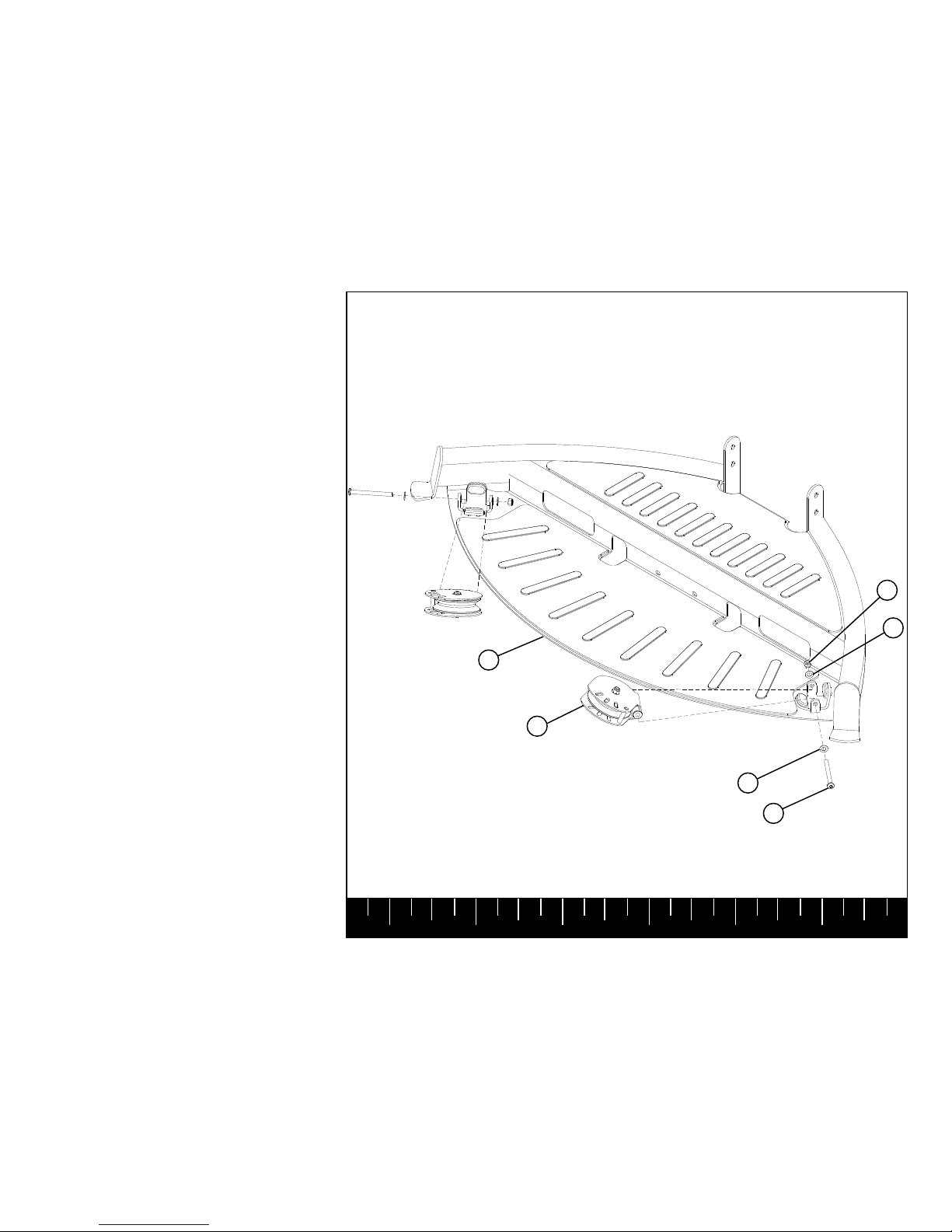
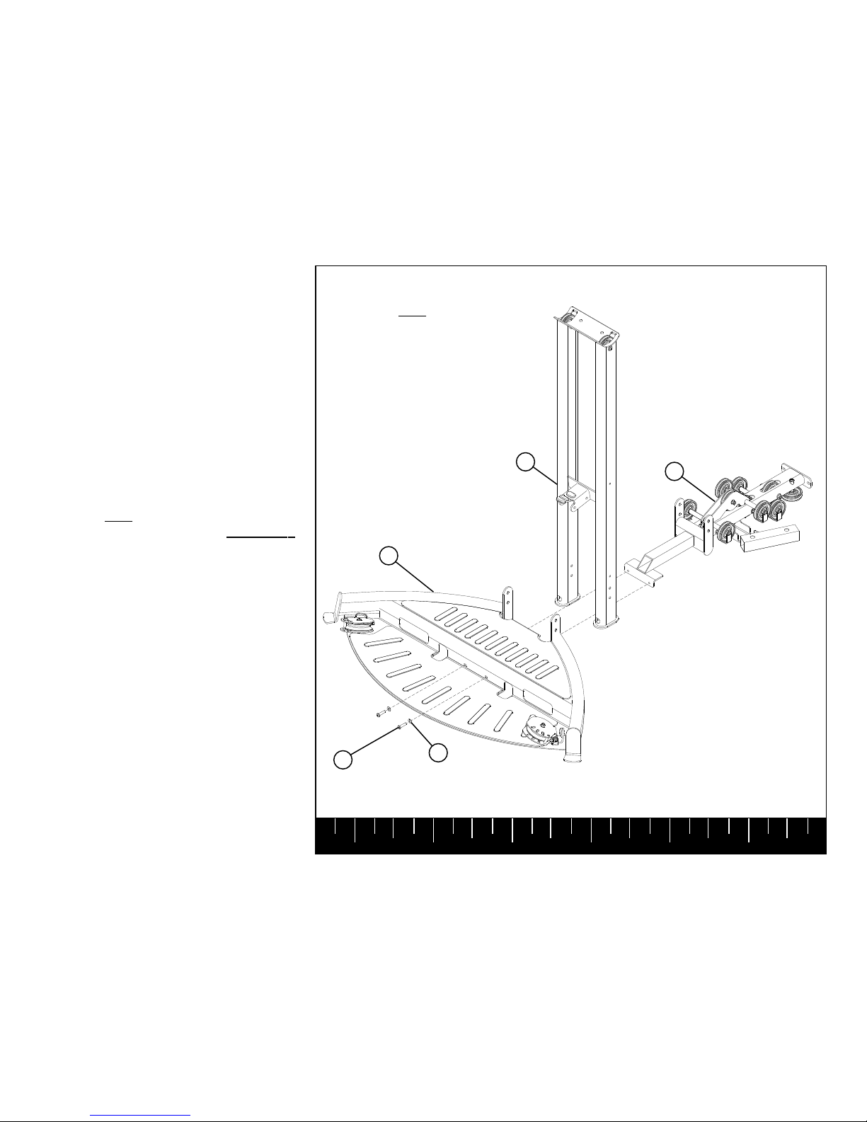
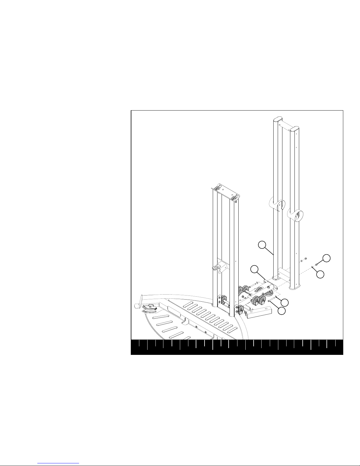
§A 6-inch scale is provided at the bottom of
every assembly instruction page. The head
of the bolt should not be used when measur-
ing the length of the bolt as depicted in the
illustration below.
123456

Page 5
Parts List
QTY
1
2
1
1
1
1
1
3
1
2
1
2
1
1
2
2
1
1
1
1
1
1
1
1
1
3
2
1
3
80
16
8
25
12
DESCRIPTION
DUAL FLOATING PULLEY
SWIVEL PULLEY
LEFT TOP SHROUD
RIGHT TOP SHROUD
LEFT BASE SHROUD
RIGHT BASE SHROUD
19 X 177.3mm TAPPED SHAFT
4-1/2” END CAP
4-1/2” OPEN END CAP
SOLID GUIDE ROD
FRONT SHROUD
FLOATING PULLEY GUIDE
KNEE HOLD DOWN
KNEE-HOLD DOWN ADJUST PLATE
FLOATING PULLEY GUIDE ROD
L-TOP GUIDE ROD BRACKET
TQ9 LEFT SHROUD
TQ9 RIGHT SHROUD
BASE
FRONT UPRIGHT
TOP FRAME SUPPORT
TOP BOOM
PLATFORM
WEIGHT STACK BOOM
REAR UPRIGHT
UPPER SWIVEL PULLEY
3-1/2” THREAD FLOATING PULLEY
TQ9 PRESS ARM
3/8” FENDER WASHER
3/8” FLATWASHER
1/4” FLATWASHER
1/4” LOCK NUT
3/8” LOCK NUT
3/8 X 3/4” NP BUTTON HEAD BOLT
#
1
2
3
4
5
6
7
8
9
10
11
12
13
14
15
16
17
18
19
20
21
22
23
24
25
26
27
28
29
30
31
33
34
35
PART NO.
50248PA
50302PA
50318PA
50319PA
50320PA
5032101
5041001
5031601
5040601
5024501
50716PA
50892PA
50874PA
5087801
5090501
5090201
5096801
5096901
50059PA
50049PA
5005601
5022401
50134PA
50238PA
50053PA
50229PA
50246PA
50207PA
2000901
2001101
2002101
2002001
2001201
2004001
QTY
8
2
10
10
2
10
4
4
4
2
1
2
1
1
2
2
1
2
1
1
1
1
1
1
1
1
1
2
1
1
2
2
1
1
DESCRIPTION
1/4 X 3/4” BUTTON HEAD BOLT
3/8 X 5-1/2” BUTTON HEAD BOLT
3/8 X 3” BUTTON HEAD BOLT
3/8 X 2-3/4” BUTTON HEAD BOLT
3/4” FLANGE SPACER
3/8 X 1” BUTTON HEAD BOLT
3/8 X 1-3/4 NP BUTTON HEAD BOLT
3/8 X 3-3/4” BUTTON HEAD BOLT
3/8” ORANGE PIVOT WASHERS
SNAP HOOK
ALUMINUM HANDLE
UNIVERSALADAPTER
ANKLE STRAP
AB/TRICEPS STRAP
ADJ STRAP HANDLE
SHORT STRAP HANDLE
LATBAR - DUAL PULLEY
SWIVEL PULLEY CABLE
LEG CURL/EXT CABLE
FLOATING PULLEY CABLE
WEIGHT STACK CABLE
LE/LC FRAME
LE/LC LEFT LEG PIVOT
LE/LC RIGHT LEG PIVOT
LE/LC CAM
LE/LC PEDESTAL
LE/LC KNEE HOLDDOWN
19 X 65mm TAPPED SHAFT
LE/LC SEATPAD
LE/LC BACK PAD
LE/LC BACK PAD PLATE
FLANGE NYLON BUSHING
LE/LC UPPER CONNECTOR
LE/LC TUBE JOINT PLATE
#
36
37
38
39
40
41
42
43
44
45
46
47
48
49
50
51
52
53
54
55
56
57
58
59
60
61
62
63
64
65
66
67
68
69
PART NO.
2001902
2001020
2001010
2001009
5099501
2001002
2004005
2001013
5101001
5091801
5051501
5091901
5091701
5091601
5091401
5044101
5091201
5098701
5099001
5098901
5098801
50034PA
50965PA
50964PA
50019PA
50021PA
50996PA
5034201
5033001
5051701
5004401
5004501
5033401
5034301

Page 6
Parts List
QTY
1
2
1
1
1
1
2
19
2
1
1
DESCRIPTION
3-1/2" SINGLE FLOATING PULLEY
SLEEVE, CABLE END
LE/LC LOWER CONNECTOR
LEG HANDLE
LE/LC BACK PAD SUPPORT
3-1/2” PULLEY
3/4” SPACER
WEIGHT PLATE
WEIGHT STACK CUSHION
WEIGHT STACK HEAD PLATE
WEIGHT STACK SELECTOR FORK
#
70
71
72
74
75
76
77
78
79
80
81
PART NO.
50717PA
5097301
5045001
50028PA
50042PA
5094401
5092001
5050901
5098201
5050401
5051201
QTY
1
2
8
19
2
1
1
1
2
DESCRIPTION
WEIGHT STACK LABEL
19mm SHAFT COLLAR
3/8” CURVED WASHER
3/8 X 1/2” BUTTON HEAD BOLT
GUIDE ROD LUBE
TQ9 WALL CHART
SILVER TOUCH-UP PAINT
GRAY TOUCH-UP PAINT
3/8 X 3-1/2” BUTTON HEAD BOLT
#
82
83
84
85
86
87
88
89
90
PART NO.
5093101
5095301
2003001
2001026
5101501
5101401
5110001
5110101
2001012

Page 7
123456
STEP 1
SECURELYassemble the two SWIVEL PUL-
LEYS (2) to the PLATFORM (23) using:
Two 3/8 X 3-3/4” BOLTS (43)
Four 3/8” FLATWASHERS (30)
Two 3/8” LOCK NUTS (34)
(NOTE: Do not overtighten - SWIVEL PUL-
LEYS should rotate freely.)
3/8X3-3/4” 43
30
34
30
23
2

Page 8
123456
STEP 2
NOTE: Item (20) must be positioned be-
tween items (23) and (19) prior to assembly.
Position the FRONT UPRIGHT (20) between
the PLATFORM (23) and the BASE (19) as
shown.
Assemble the PLATFORM (23) to the BASE
(19) using:
Two 3/8X1” BOLTS (85)
Two 3/8” FLATWASHERS (30)
NOTE: Do NOT fully tighten any connec-
tions until instructed to do so SECURELY.
85
23
41 3/8X1”
19
20
NOTE: Do NOT fully tighten.

Page 9
123456
STEP 3
Assemble the FRONT UPRIGHT (20) to the
PLATFORM (23) and the BASE (19) using:
Four 3/8X3” BOLTS (38)
Eight 3/8” FLATWASHERS (30)
Four 3/8” LOCK NUTS (34)
38 3/8X3”
23 30
19
20
34

Page 10
123456
STEP 4
Assemble the REAR UPRIGHT (25) to the
BASE (19) using:
Two 3/8X 2-3/4” BOLTS (39)
Four 3/8” FLATWASHERS (30)
Two 3/8” LOCK NUTS (34)
39 3/8X2-3/4”
19
25
34
30
30

Page 11
123456
STEP 5
Assemble the TOP FRAME SUPPORT(21) to
the REAR UPRIGHT (25) using:
Two 3/8X2-3/4” BOLTS (39)
Four 3/8” CURVED WASHERS (84)
Two 3/8” LOCK NUTS (34)
Assemble the TOP BOOM (22) to the TOP
FRAME SUPPORT(21) and FRONT UP-
RIGHT (20) using:
Two 3/8X5-1/2” BOLTS (37)
Four 3/8” CURVED WASHERS (84)
Two 3/8” LOCK NUTS (34)
SECURELYtighten the previous frame con-
nections.
37 3/8X5-1/2”
3/8X2-3/4” 39
34
34
84
84
22
21
84
84
20
25

Page 12
123456
STEP 6
SECURELYassemble the KNEE HOLD
DOWN (13) to the FRONT UPRIGHT(20)
using:
One KNEE HOLD DOWN ADJ PLATE (14)
One 3/8 X 1” BOLT(41)
Two 3/8 X 3/4” BOLTS (35)
Four 3/8” FLATWASHERS (30)
One 3/8” LOCK NUT (34)
(NOTE: Pull back on the KNEE HOLD
DOWN POP PIN and check to make sure the
POP PIN shaft engages in the KNEE HOLD
DOWN ADJUST PLATE)
34
14
3/8X1” 41
13
30
20
POP
PIN
3/8X3/4” 35

Page 13
123456
STEP 7
Insert one 19 X 177.3mm TAPPED SHAFT (7)
into the PRESS ARM (28) as shown.
Center the 19 X 177.3mm TAPPED SHAFT (7)
in the PRESS ARM (28) and slide the PRESS
ARM (28) up through the slotsin the REAR
UPRIGHT (25) as shown.
SECURELYassemble the PRESS ARM (28) &
19 X 177.3mm TAPPED SHAFT (7) to the
REAR UPRIGHT (25) using:
Two 3/8X3/4” BOLTS (35)
NOTE: Bolts must be tightened simulta-
neously.
7
25
3/8X3/4” 35
28
SECURELY
TIGHTEN
SIMULTANEOUSLY!

Page 14
123456
STEP 8
19
79
10
83
81
78
80
Apply GUIDE ROD LUBE (86) liberally over
entire length of both SOLID GUIDE RODS (10).
Insert two GUIDE RODS (10) into the bracket
on the BASE (19)
Slide two WEIGHT STACK CUSHIONS (79)
down over the SOLID GUIDE RODS (10).
CAREFULLYslide nineteen WEIGHT PLATES
(78) down over the SOLID GUIDE RODS (10)
!
CAREFULLYslide the HEAD PLATE (80)
down over the SOLID GUIDE RODS (10) onto
the top of the WEIGHT PLATES (78)
NOTE: Make sure selector stop on head
plate faces as shown.
Slide two 19mm SHAFT COLLARS (83) down
over the SOLID GUIDE RODS (10) onto the
top of the HEAD PLATE (80)
Insert the TORQUE FORK
TM
(81) into the
WEIGHT PLATE (78) as shown.
NOTE: Flange part of spacer on
WEIGHT PLATE faces upward and
label indentation faces outward.
FLANGE
SPACERS

Page 15
123456
STEP 9
Lower the WEIGHT STACK BOOM(24) onto
the SOLID GUIDE RODS (10) as shown.
SECURELYassemble the WEIGHT STACK
BOOM (24) to the TOP FRAME SUPPORT
(21) using:
Two 3/8X2-3/4” BOLTS (39)
Four 3/8” FLATWASHERS (30)
Two 3/8” LOCK NUTS (34)
Slide the two 19mm SHAFT COLLARS (83) up
against the WEIGHT STACK BOOM (24) and
tighten the set screws on the 19mm SHAFT
COLLARS (83) SECURELY.
Assemble the WEIGHT STACK LABELS (82)
to the WEIGHT STACK. Start with label #1
on the HEAD PLATE (80).
83
10
24
3/8X2-3/4“ 39
30
34
21
30
82
80

Page 16
123456
STEP 10
NOTE: Do NOT fully tighten any connec-
tions until instructed to do so SECURELY.
Assemble the UPPER LEG CURL/EXT CON-
NECTOR (68) to the LEG CURL/EXT FRAME
(57):
Two 3/8X3” BOLTS (38)
Four 3/8” FLATWASHERS (30)
Two 3/8” LOCK NUTS (34)
Assemble the LOWER LEG CURL/EXT CON-
NECTOR (72) to the LEG CURL/EXT FRAME
(57):
Two 3/8X2-3/4” BOLTS (39)
Four 3/8” FLATWASHERS (30)
Two 3/8” LOCK NUTS (34)
3/8X2-3/4” 39
3/8X3” 38
30
34
30
72
57
30
30
34
68

Page 17
123456
STEP 11
Slide the 4-1/2” OPEN END CAP (9) over the
UPPER LEG CURL/EXT CONNECTOR (68)
as shown.
SECURELYassemble the LEG CURL/EXT
TUBE JOINT PLATE (69) to the UPPER LEG
CURL/EXT CONNECTOR (68) using:
Two 3/8X1” BOLTS (41)
Two 3/8” FLATWASHERS (30)
3/8X1” 41
57
68
9
69
NOTE: Slide item 9 onto item 68
prior to attaching item 69.
30

57
Page 18
123456
STEP 12
(NOTE: Do NOT SECURELYtighten LEG
STATION to main FRAME until instructed to
do so.)
Assemble the LEG CURL/EXT TUBE JOINT
PLATE (69) to the REAR UPRIGHT (25) using:
Two 3/8 X 1” BOLTS (41)
Two 3/8” FLATWASHERS (30)
Assemble the LOWER LEG CURL/EXT CON-
NECTOR (72) to the PLATFORM (23) using:
Two 3/8 X 2-3/4” BOLTS (39)
Two 3/8” FLATWASHERS (30)
(NOTE: Do not insert 4-1/2” OPEN END CAP
(9) until all BOLTS are SECURELYtighened
in a later step.)
(NOTE: The back tube on the LEG EXT/
CURL LEG FRAME (57) will be attached to
the REAR UPRIGHT (25) in a later step when
the SHROUDS are assembled.)
9
69
30
72
3/8 X 2-3/4” 39
25
23
30
41 3/8X1”
ATTACH IN
LATER STEP

Page 19
123456
STEP 13
Assemble the LEG CURL/EXT HANDLE (74)
to the LEG CURL/EXT FRAME (57) using:
Two 3/8 X 1-3/4” BOLTS (42)
Four 3/8” FLATWASHERS (30)
Two 3/8” LOCK NUTS (34)
42 3/8X1-3/4”
30
74 30
34
57

Page 20
123456
STEP 14
Assemble the LEG CURL/EXT LEFT LEG
PIVOT (58) & RIGHT LEG PIVOT (59) to the
LEG CURL/EXT KNEE HOLDDOWN (62) &
LEG CURL/EXT HANDLE (74) using:
One 19 X 65mm TAPPED SHAFT (63)
Two 3/8 X 1-3/4” BOLTS (42)
Two 3/8 X 3-1/2” BOLTS (90)
Two ORANGE PIVOT WASHERS (44)
Four 3/8” FLATWASHERS (30)
Two 3/4” SPACERS (77)
Two 3/4” FLANGE SPACERS (40)
One 3-1/2” PULLEY (76)
Two 3/8” LOCK NUTS (34)
Note: The labels on the LEFT & RIGHT LEG
PIVOTS (58 & 59) should face outward.
30
34
58
77
3/8 X 1-3/4” 42
90 3/8X3-1/2”
76
74
59
40
63
33
ORANGE PIVOT
WASHERS
62
44
Table of contents
Other Torque Fitness Home Gym manuals
Popular Home Gym manuals by other brands

Impex
Impex APEX II owner's manual

BH FITNESS
BH FITNESS COMBO DUO Instructions for assembly and use

Inspire
Inspire M5 Assembly & operation manual

Impex
Impex Circuit Fitness AMZ-986RW-BT owner's manual

Reebok
Reebok ZJET 460 ROWER Assembly guide

CORFLEX
CORFLEX Marathon Air Walker Ankle Application Instructions