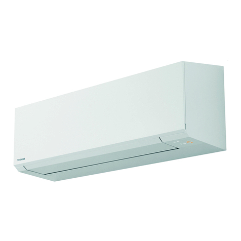
Toshiba XXXXXXX(<SanSerif1>X/X)
8
EN
Outdoor Unit Installation Manual
9TEST OPERATION
Wiring/Piping Check
Electric current is applied on the control board. Beware of
electric shock.
1. Detach the front panel of the outdoor unit.
Do not remove the air discharge grille.
2. Turn on the circuit breaker to supply electricity.
3. Start running all the indoor units connected to the outside unit in the cooling
mode.
• You need not specify the temperature setting of the indoor units.
• You cannot check wiring/piping when the external temperature is 5°C or
less.
4. Turn on the SW802 No.4 switch on the P.C board MCC 5071.
The wiring/piping check starts automatically.
While checking, each LED flashes consecutively to indicate that the
checking each indoor unit is in progress.
When checking is complete, the check result is displayed on the LED panel.
See the table below for details.
5. Turn off the SW802 No.4 switch on the P.C board MCC 5071.
• The checking operation changes to the normal operation.
Gas Leak Inspection
Refer to the “Gas Leak Inspection“ on page 6.
Test Operation
1. If you perform the test operation in summer, start running in the cooling
mode first to decrease the temperature of the room, then run in the heating
mode. (Heating mode: Set the temperature to 30°C.)
• If you perform the test operation in winter, start running in the heating mode
first to increase the temperature of the room, then run in the cooling mode.
(Cooling mode: Set the temperature to 17°C.)
2. For the test operation, be sure to satisfy the following conditions below:
- Perform the test operation for each indoor unit respectively.
- Perform the test operation for about 10 minutes in both the cooling mode
and the heating mode.
•
You can perform the test operation in the cooling/heating mode by utilizing the
thermo sensor of the indoor unit.
Cooling mode: Warm the thermo sensor using an appliance such as a hair dryer.
Heating mode: Put a cold towel on the thermo sensor.
Instructions for the Customers
• Explain to the customers the proper operation procedure and let them
operate the air conditioner along with the supplied instruction manual.
• When multiple indoor units are connected to the outdoor unit, the cooling
mode and the heating mode are not available at the same time.
When multiple indoor units are running at the same time, the operation
mode of the unit which starts running first is applied to the other units.
• When you start running the indoor unit or change the operation mode, the
unit starts running after 3 minutes. This is due to the protection function of
the unit, not a malfunction.
• When the external temperature becomes low, the pre-heating of the
compressor starts to protect it. Keep the circuit breaker on for use.
The electricity consumption during pre-heating is about 100W.
If the circuit breaker is turned off, the indoor unit may not start running for
about 11 minutes.
• Electronic expansion valves are used for the outdoor unit.
When you turn on the power, the outdoor unit starts clattering every 1 or 2
months. This clattering is not a malfunction, but occurs when the unit is
returning to the default setting for optimised control.
• While an indoor unit is running in the heating mode, the outdoor unit
supplies refrigerant to the other indoor units which are not running.
Therefore, noise may come from the other indoor units or the exterior of
them may become warm.
4-1. If no problems are detected, The checking operation returns to the
normal operation automatically.
The compressor stops temporarily, then it restarts.
The D801 LED flashes while the compressor is stopped.
4-2. If incorrect wiring/piping is detected, The checking operation stops.
Check the status of the LED to confirm the details of the problem.
Turn off the circuit breaker, then check wiring/piping again.
: LED ON, : LED OFF, : LED Flash
LED
Description
D800 D801 D802 D803 D804 D805
Before
check
Normal operation (no error)
During
check
Checking A unit
Checking B unit
Checking C unit
Checking D unit
Checking E unit
Check
results
Normal operation (no error)
Trouble in unit A
Trouble in unit B
Trouble in unit C
Trouble in unit D
Trouble in unit E
Trouble in units A and B
Trouble in units A and C
Trouble in units A and D
Trouble in units A and E
Trouble in units B and C
Trouble in units B and D
Trouble in units B and E
Trouble in units C and D
Trouble in units C and E
Trouble in units D and E
Trouble in units A, B, and C
Trouble in units A, B, and D
Trouble in units A, B, and E
Trouble in units A, C, and D
Trouble in units A, C, and E
Trouble in units A, D, and E
Trouble in units B, C, and D
Trouble in units B, C, and E
Trouble in units B, D, and E
Trouble in units C, D, and E
Trouble in units A, B, C, and D
Trouble in units A, B, C, and E
Trouble in units A, B, D, and E
Trouble in units A, C, D, and E
Trouble in units B, C, D, and E
"Trouble in all units
Service valve stays closed"
: LED ON, : LED OFF, : LED Flash
LED
Description
D800 D801 D802 D803 D804 D805
+00EG44206701_01EN.book Page 8 Tuesday, July 20, 2010 9:32 PM
