manuals.online logo
Brands
  1. Home
  2. •
  3. Brands
  4. •
  5. Toshiba
  6. •
  7. Air Conditioner
  8. •
  9. Toshiba RBC-U32PGP-E User manual

Toshiba RBC-U32PGP-E User manual

Other Toshiba Air Conditioner manuals

Toshiba Carrier MMU-AP0071MH2UL User manual

Toshiba

Toshiba Carrier MMU-AP0071MH2UL User manual

Toshiba RAS-10N3AV2-A User manual

Toshiba

Toshiba RAS-10N3AV2-A User manual

Toshiba RAV-SM454MUT-E User manual

Toshiba

Toshiba RAV-SM454MUT-E User manual

Toshiba RBC-AXU33UPB-E User manual

Toshiba

Toshiba RBC-AXU33UPB-E User manual

Toshiba RAV-GM901CTP-E User manual

Toshiba

Toshiba RAV-GM901CTP-E User manual

Toshiba MMU-AP0091H User manual

Toshiba

Toshiba MMU-AP0091H User manual

Toshiba RAS-22 SKVR Series User manual

Toshiba

Toshiba RAS-22 SKVR Series User manual

Toshiba RAV-RM1601BTP Series User manual

Toshiba

Toshiba RAV-RM1601BTP Series User manual

Toshiba MMK-AP0057HP-E User manual

Toshiba

Toshiba MMK-AP0057HP-E User manual

Toshiba RAV-GP561ATP-E User manual

Toshiba

Toshiba RAV-GP561ATP-E User manual

Toshiba RAC-61SE2B Mounting instructions

Toshiba

Toshiba RAC-61SE2B Mounting instructions

Toshiba RAS-18SKHP-ES User manual

Toshiba

Toshiba RAS-18SKHP-ES User manual

Toshiba RAS-3M26S3AV-E User manual

Toshiba

Toshiba RAS-3M26S3AV-E User manual

Toshiba MMU-AP0092H User manual

Toshiba

Toshiba MMU-AP0092H User manual

Toshiba MMY-MAP0804HT8(Z)(ZG)-E User manual

Toshiba

Toshiba MMY-MAP0804HT8(Z)(ZG)-E User manual

Toshiba RAS-15EK Series User manual

Toshiba

Toshiba RAS-15EK Series User manual

Toshiba RAV-GM561UT-E User manual

Toshiba

Toshiba RAV-GM561UT-E User manual

Toshiba RBC-AX33CE User manual

Toshiba

Toshiba RBC-AX33CE User manual

Toshiba RAS-13UKHP-ES3 User manual

Toshiba

Toshiba RAS-13UKHP-ES3 User manual

Toshiba RAV-SM562BT-E User manual

Toshiba

Toshiba RAV-SM562BT-E User manual

Toshiba RAC-WK0511CMU User manual

Toshiba

Toshiba RAC-WK0511CMU User manual

Toshiba RAS-B10J2KVRG-E User manual

Toshiba

Toshiba RAS-B10J2KVRG-E User manual

Toshiba RAS-M10YKV-E User manual

Toshiba

Toshiba RAS-M10YKV-E User manual

Toshiba Carrier MMD- AP0074BH2UL User manual

Toshiba

Toshiba Carrier MMD- AP0074BH2UL User manual

Popular Air Conditioner manuals by other brands

Fujitsu ASYG 09 LLCA installation manual

Fujitsu

Fujitsu ASYG 09 LLCA installation manual

York HVHC 07-12DS Installation & owner's manual

York

York HVHC 07-12DS Installation & owner's manual

Carrier Fan Coil 42B Installation, operation and maintenance manual

Carrier

Carrier Fan Coil 42B Installation, operation and maintenance manual

intensity IDUFCI60KC-3 installation manual

intensity

intensity IDUFCI60KC-3 installation manual

Frigidaire FAC064K7A2 Factory parts catalog

Frigidaire

Frigidaire FAC064K7A2 Factory parts catalog

Sanyo KS2432 instruction manual

Sanyo

Sanyo KS2432 instruction manual

LG MultiV Series installation manual

LG

LG MultiV Series installation manual

CLIMAVENETA a-CHD U-2T 606+2209 OPERATING AND INSTALLATION Manual

CLIMAVENETA

CLIMAVENETA a-CHD U-2T 606+2209 OPERATING AND INSTALLATION Manual

Midea EWK06CW5 user manual

Midea

Midea EWK06CW5 user manual

Pioneer FAB Series installation manual

Pioneer

Pioneer FAB Series installation manual

SPT WA-1511S user manual

SPT

SPT WA-1511S user manual

Mitsubishi Electric Mr.Slim MSZ-A24NA operating instructions

Mitsubishi Electric

Mitsubishi Electric Mr.Slim MSZ-A24NA operating instructions

Mitsubishi Electric PUHZ-RP50VHA4 Service manual

Mitsubishi Electric

Mitsubishi Electric PUHZ-RP50VHA4 Service manual

Panasonic CS-S18HKQ Service manual

Panasonic

Panasonic CS-S18HKQ Service manual

Panasonic CS-E15NKE3 operating instructions

Panasonic

Panasonic CS-E15NKE3 operating instructions

Gree GWH18TC-K3DNA1B/I Service manual

Gree

Gree GWH18TC-K3DNA1B/I Service manual

Friedrich ZoneAire Compact P08SA owner's manual

Friedrich

Friedrich ZoneAire Compact P08SA owner's manual

Daikin R32 Split Series installation manual

Daikin

Daikin R32 Split Series installation manual

manuals.online logo
manuals.online logoBrands
  • About & Mission
  • Contact us
  • Privacy Policy
  • Terms and Conditions

Copyright 2025 Manuals.Online. All Rights Reserved.

1-EN
-
1
-
Ceiling panel
Model : RBC-U32PGP-E
Precautions for safety
• The product and this manual are provided with important safety notices to ensure safe use and protect the user and
other people from hazards and preclude damage to property.
Be sure that you fully understand the following contents (expressions and graphic symbols) and read this manual
carefully. Always observe the precautions.
WARNING
• Ask an authorized dealer or qualified installation professional to install the ceiling panel.
Inappropriate installation may result in water leakage, electric shock or fire if you install it by yourself.
• Carry out an installation work securely according to this Installation Manual.
Inappropriate installation may result in water leakage, electric shock or fire.
• Attach the ceiling panel on a ceiling that withstands the weight of the ceiling panel.
Insufficient strength may cause a fall of the unit, which may result in injury.
• Electrical work must be performed by a qualified electrician in accordance with the Installation Manual.
Make sure the air conditioner uses an exclusive power supply.
The capacity shortage of the power circuit or improper electrical work may result in electric shock or fire.
• Connect the specified wires firmly and clamp them securely so that external force applied to the wires does
not affect the connector pins.
Improper wire connection or clamping may result in fire or malfunction.
• Be sure to connect earth wire. (grounding work)
Do not connect the earth wire to a gas pipe, water pipe, lightning conductor, or a telephone earth wire.
Incomplete earthing may result in electric shock.
• Never modify or repair the product.
Incomplete modification or repair may result in electric shock or fire.
CAUTION
• Wear heavy work gloves during the installation work to avoid injury.
Components
Part name Ceiling panel Installation manual REQUIREMENT
Do not apply excessive force
to the louver, as it may cause a
malfunction.
Quantity 1 1
Shape
Louver This manual
INSTALLATION MANUAL
2-EN
-
2
-
1. Preparation for attaching ceiling panel
Checking indoor unit position
1. Check the position of the indoor unit using the Installation
Manual.
2. Check whether the ceiling opening size falls within a range
of 860 × 860 to 910 × 910.
3. Determine the positional relation between the ceiling and
the indoor unit using the installation gauge supplied with
the indoor unit. Improper positioning of the indoor unit may
result in air/water leakage or malfunction of the louver.
• Do not put the ceiling panel facing down or lean
it against a wall, etc. or put it on an object with
projection to avoid scratches on the surface.
Handle the ceiling panel carefully so as not to deform
the movable hooks.
This clearance must be 12 to 17.
A clearance outside this range may cause malfunction.
Indoor unit
Ceiling opening size
Ceiling
Installation gauge
(supplied with the indoor unit)
12 to 17
2. Attaching ceiling panel to indoor unit
Detaching air intake grille Air intake grille Ceiling panel
Adjust corner cap
Knobs of air intake grille hooks
2
Safety strap
hook
Ceiling panel hook hole
Hinges
1
Knob
Adjust
corner
cap
Adjust corner
cap
Strap
Ceiling panel
Open
Keep the bracket
open.
Closed
Panel fixing
bracket
Open Close
(Fig. 1) (Fig. 2)
1. Slide the knobs of the hooks of the air intake grille in the
direction of arrow 1, and open the grille.
2. Release the safety strap hook from the ceiling panel.
• Do not remove the safety strap screw on the air
intake grille side.
3. Remove the hinges on the air intake grille from the ceiling
panel in the direction of arrow 2with the grille open.
Detaching adjust corner caps
1. Pull the knob of the adjust corner cap in the direction of
arrow 1, and detach the adjust corner caps from the four
corners.
• The knob is provided only on one side of the cap.
Detach the adjust corner caps from the knob side.
Checking panel fixing bracket position
After the adjust corner caps are detached, check that the
panel fixing bracket is open (Fig. 1).
• The ceiling panel cannot be attached to the indoor unit with
the bracket closed (Fig. 2).
3-EN
-
3
-
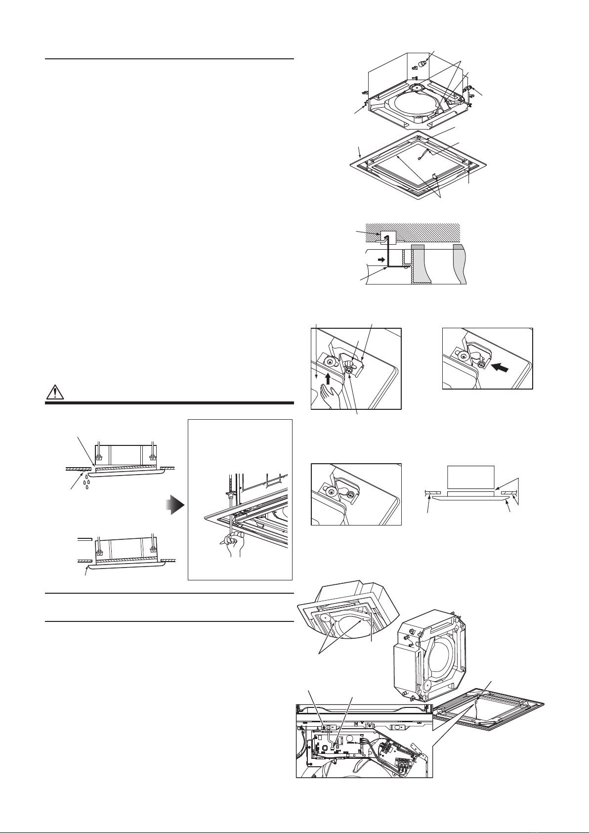
Attaching ceiling panel (Fig. 1)
(Fig. 2)
Drain pipe
Rectangular holes of
indoor unit
Electrical control box
Refrigerant pipe
Panel fixing screw
Ceiling panel
Marking: Drain pipe side
louver motor wire
Marking: Refrigerant pipe side
Movable hook
Rectangular hole of
indoor unit
Push when releasing
Movable hook
(Fig. 3)
(Fig. 5)
(Fig. 4)
(Fig. 6)
Panel inner frame Panel fixing bracket
Hole
Panel fixing screw
Lift the panel inner frame to make
the screw head visible.
Push the panel fixing bracket
securely.
Indoor unit No gap
Ceiling panel
Bottom of ceiling
Tighten the panel fixing screw.
REMOTECONTROLLER
B
A
Pass the wire through the clamper
as illustrated.
louver motor wire
Wire Connection (For illustrative purpose, the
orientation of the indoor unit is not the actual
orientation.)
Electrical control
box cover
Two screws
Clamper
CN510
Do not apply excessive force to the louver when attaching
the ceiling panel, as it may cause malfunction of the louver.
1. Insert the two movable hooks at the inside of the ceiling
panel into the rectangular holes of the indoor unit, and hook
them tentatively onto the indoor unit. (Fig. 1 and Fig. 2)
• The ceiling panel has an orientation to the indoor unit
for installation. Attach the ceiling panel so that the louver
motor wire comes to the electrical control box side.
• To detach the ceiling panel, push the movable hooks
outward while holding the ceiling panel.
2. Lift the corner of the panel inner frame and insert the panel
fixing screw of the indoor unit into the panel fixing bracket
hole (Fig. 3). Then slide the panel fixing bracket in the
direction of arrow and push it to the specified position
(Fig. 4). Repeat this procedure for the four panel fixing
brackets.
• Slide the panel fixing bracket while keeping the screw
head lower than the bracket.
• The panel fixing screws have been attached to the indoor
unit since its shipping.
3. Tighten the four panel fixing screws to secure the ceiling
panel until it comes into close contact with the indoor unit.
(Fig. 5)
4. Check that the ceiling panel is in close contact with the
ceiling.
• Make sure that there is no gap between indoor unit and
ceiling panel and between ceiling panel and bottom of the
ceiling. (Fig. 6)
CAUTION
Air leakage
Air leakage
from bottom
of the ceiling
Contamination
Dew drop/water leakage
• If a gap between ceiling panel and
bottom of the ceiling still remains
after the screws are tightened,
readjust the height of the indoor unit.
No gap
After the adjustment of height, tighten
the nuts of the indoor unit securely.
The height of the indoor unit can be
adjusted from the corner holes of the
ceiling panel without detaching the
panel, provided that the levelness of
the indoor unit and the drain pipe are
not affected.
• Insufficient tightening of the screws may result in the
following problems. Tighten the screws securely.
Connecting wires of ceiling panel
1. Remove the two screws of the electrical control box cover,
and detach the electrical control box cover by pressing the
hook. (The electrical control box cover is clamped onto the
hinge.)
2. Pass the louver motor wire from the ceiling panel through
the clamper as shown, and connect the wire to the white
20P connector CN510 on the P.C. board of the indoor unit.
• Connect the wire firmly to the connector to ensure
operation of the louver.
3. Attach the electrical control box cover by reversing the
procedure of detaching.
• Make sure that no wire is caught between the
electrical control box and the cover.
• Make sure that no wire is caught between the indoor
unit and the ceiling panel.
4-EN
-
4
-
1114370699
Attaching adjust corner caps and air
intake grille
Brand name indication given at factory shipping
Adjust corner cap
* Can be attached at any location.
Indoor unit electrical control box
Wireless Remote Controller Kit
(separate sold parts)
* Can be installed only at this
location.
Refrigerant
pipe side
Drain pipe
side
Omnidirectional 360°
Locations of air intake grille hook knobs
(attached when the product was shipped)
* These knobs can be attached on any
side of the four sides, but attaching
them on this side is recommended.
Attaching air intake grille
• Attach the air intake grille by reversing the procedure of
its removal. The air intake grille of this ceiling panel can
be attached in four patterns by turning the grille. Select
the orientation of the grille for alignment when multiple
ceiling panels are attached or according to customer
requirements.
• Attach the air intake grille so as not to catch the
louver motor wire.
• Be sure to attach the safety strap of the air intake
grille to the ceiling panel.
Hook hole of ceiling panel
Safety strap
hook
• According to customer requirements, the grille orientation of
the air intake grille and the location of the company name
indication on the adjust corner cap can be changed as
shown in the figure (right) for installation of multiple units.
However, the Wireless Remote Controller Kit (separate sold
parts) can be installed only at the diagonal corner of the
drain pipe of the indoor unit. If the Kit is installed at another
location, it may cause malfunction of the Kit.
Attaching adjust corner caps
Hook the strap of the adjust corner cap securely to the pin of
the ceiling panel.
Pin Claws A (insert to fit)
Claws B (press to fit)
Insert the two claws A of the adjust
corner cap into the rectangular holes
of the ceiling panel in the direction of
arrow.
Press the adjust corner cap so that
the three claws B on the back of the
cap are fitted.
Rectangular
holes Claws A
Claws B
Firmly press edges of the
adjust corner cap.
CAUTION
• Press the three claws B of the adjust corner cap
firmly as far as they will go, and then check that the
adjust corner cap is closely attached. Failure to do
so may result in water leakage.
3. Other descriptions
Checks after Installation
• Reconfirm that there is no gap between indoor unit and ceiling panel or between ceiling panel and bottom of ceiling.
* Such gap may result in water leakage or dew drop.
• Confirm that all wires are connected correctly and firmly.
* Otherwise, the louver does not work.
• Confirm that the claws of the adjust corner caps are fitted securely.
* Improper fitting may result in water leakage.
When Using Wireless Remote Controller
• For details of the installation, refer to the Installation Manual supplied with the Wireless Remote Controller Kit
(separate sold parts).
Delivery to Customer
• When the installation work has been completed, execute a test run to check for normal operation.
Then explain how to use and maintain the ceiling panel to the customer according to the Owner’s Manual of the indoor unit.
Ask the customer to keep this installation manual with the Owner’s Manual and Installation Manual of the indoor unit.