Toshiba 13A20 User manual

SERVICE MANUAL
– SUMMARY –
N0E Chassis
13A20
COLOR TELEVISION
(TAC0002)
FILE NO. 063-200004
PUBLISHED IN JAPAN, Jun., 2000 S
13A20 is the same as 19A20 except for the parts and setting & adjusting data tabled
on back of this sheet.
Use this service manual together with the service manual of 19A20 (File No. 020-200003).

TOSHIBA CORPORATION
1-1, SHIBAURA 1-CHOME, MINATO-KU, TOKYO 105-8001, JAPAN
Location
No. Part No. Description
A201 23549359 Front Cover
A401 23003326 Back Cover
A701 23525910 Carton
C230 24794470 EL, 47?F, ±20%, 16V
C310 24796470 EL, 47?F, ±20%, 35V
C311 24214101 CD, 100pF, ±10%, 500V
C314 24590563 PF, 0.056?F
C440 24082952 PF, 6200pF, ±3%, 1500V
C442 24082693 PF, 0.33?F, 250V
C611 24591104 PF, 0.1?F
C810 24086939 EL, 330?F, ±20%, 200V
C832 24794470 EL, 47?F, ±20%, 16V
D102 23118528 Diode, Zener, RD5.6ESA B3
D201 23118632 Diode, Zener, RD3.3ESA B1
D472 23115774 Diode, Zener, RD6.2E(4)
L462 23231183 Deflection Yoke, TDY-314QY
L901 23200306 Coil, Degaussing, TSB-2219AL
P801 23372123 Power Cord
Q101 23114552 Transistor, 2SC1685-Q, TH
R227 24366473 CF, 47k ohm
R304 24366473 CF, 47k ohm
R305 24322159 MF, 1.5 ohm, 1W
R306 24366683 CF, 68k ohm
R307 24366474 CF, 470k ohm
R312 24381222 OMF, 2200 ohm, 1/2W
R313 24366274 CF, 270k ohm
R317 24366243 CF, 24k ohm
R327 24338689 MF, 6.8 ohm, 1W
Location
No. Part No. Description
R416 24019327 OMF, 2700 ohm, 5W
R475 24367821 CF, 820 ohm, ±2%
R802 24376274 CF, 270k ohm, 1/2W
R808 24000209 PTC Thermistor, 12 ohm,
±20%, AC140V
R810 24510229 Cement, 2.2 ohm, 5W
R811 24569241 Cement, 240 ohm, 10W
R812 24510689 Cement, 6.8 ohm, 5W
R830 24381560 OMF, 56 ohm, 1/2W
R897 24019473 Varistor, ERZ10V271K2
R920 24000568 FR, 4.7 ohm, 1W
R921 24366471 CF, 470 ohm
R922 24366471 CF, 470 ohm
R923 24366471 CF, 470 ohm
R931 24366122 CF, 1200 ohm
R932 24366122 CF, 1200 ohm
R933 24366122 CF, 1200 ohm
* T461 23236589 Transformer, Flyback,
TFB4139AY
*U901 Main Board, PB9391B-1
* V901 23312577 Picture Tube, A34JFQ90X(VW)
V901M 23102409 Magnet, Purity-Convergence,
MAG-1070
W661 23351112 Speaker, SPK-1379,
77x77mm, 8 ohm
Y101 23563952 Owner’s Manual,
English/French, 13A20
REPLACEMENT PARTS LIST DIFFERENCES
SETTING & ADJUSTING DATA DIFFERENCES
13"
HIGH VOLTAGE AT ZERO BEAM: (A) 23.5 kV
MAX HIGH VOLTAGE: (B) 24.9 kV
Table-1
SAFETY INSTRUCTIONS
CIRCUIT CHECKS
Table-4
FBT DETECTION VOLTAGE (C) 21.02V

TOSHIBA CORPORATION
1-1, SHIBAURA 1- CHOME, MINATO-KU, TOKYO 105-8001, JAPAN
FILE NO. 020-200003
SERVICE MANUAL
COLOR TELEVISION
N0E Chassis
19A20
PRINTED IN U.S.A. Mar., 2000 U
(TAC0001)

– 2 –
GENERAL ADJUSTMENTSSPECIFIC INFORMATIONS
TABLE OF CONTENTS
CHAPTER 1 GENERAL ADJUSTMENTS
SAFETY INSTRUCTIONS........................................................................................................................................3
SET-UP ADJUSTMENT ............................................................................................................................................4
SERVICE MODE ......................................................................................................................................................8
DESIGN MODE ...................................................................................................................................................... 11
ELECTRICALADJUSTMENTS ..............................................................................................................................12
CIRCUIT CHECKS .................................................................................................................................................14
CHAPTER 2 SPECIFIC INFORMATIONS
SETTING & ADJUSTING DATA .............................................................................................................................15
LOCATION OF CONTROLS...................................................................................................................................16
PROGRAMMING CHANNEL MEMORY.................................................................................................................17
CIRCUIT BLOCK DIAGRAM ..................................................................................................................................18
CHASSIS AND CABINET REPLACEMENT PARTS LIST......................................................................................19
PC BOARDS BOTTOM VIEW ................................................................................................................................23
TERMINAL VIEW OF TRANSISTORS ...................................................................................................................26
SPECIFICATIONS ..................................................................................................................................................29
APPENDIX:
CIRCUIT DIAGRAM

– 3 –
GENERAL ADJUSTMENTSSPECIFIC INFORMATIONS
CHAPTER 1 GENERAL ADJUSTMENTS
SAFETY INSTRUCTIONS
WARNING: BEFORE SERVICING THIS CHASSIS, READ THE “X-RAY RADIATION PRECAUTION”, “SAFETY PRECAU-
TION” AND “PRODUCT SAFETY NOTICE” INSTRUCTIONS BELOW.
X-RAY RADIATION PRECAUTION
1. Excessive high voltage can produce potentially hazard-
ous X-RAY RADIATION.To avoid such hazards, the high
voltage must not be above the specified limit.The nominal
value of the high voltage of this receiver is (A) kV at zero
beam current (minimum brightness) under a 120V AC
power source. The high voltage must not, under any cir-
cumstances, exceed (B) kV.
Refer to table-1 for high voltage (A), (B).
(See SETTING & ADJUSTING DATA on page 15)
Each time a receiver requires servicing, the high voltage
should be checked following the HIGH VOLTAGE CHECK
procedureinthis manual. It is recommended thattheread-
ing of the high voltage be recorded as a part of the service
record. It is important to use an accurate and reliable high
voltage meter.
2. Thisreceiverisequippedwith a Fail Safe (FS) circuit which
prevents the receiver from producing an excessively high
voltage even if the B+ voltage increases abnormally.Each
timethereceiveris serviced, theFScircuitmustbechecked
to determine that the circuit is properly functioning, follow-
ing the FS CIRCUIT CHECK procedure in this manual.
3. The only source of X-RAY RADIATION in this TV receiver
is the picture tube.For continued X-RAY RADIATION pro-
tection, the replacement tube must be exactly the same
type tube as specified in the parts list.
4. Somepartinthisreceiverhavespecialsafety-relatedchar-
acteristics for X-RAY RADIATION protection. For contin-
ued safety, parts replacement should be undertaken only
after referring to the PRODUCT SAFETY NOTICE below.
SAFETY PRECAUTION
Connect a 1500 ohm 10 watt resistor, paralleled by a 0.15
µF, ACtypecapacitor,betweenaknowngoodearthground
(water pipe, conduit, etc.) and the exposed metallic parts,
one at a time. Measure the AC voltage across the combi-
nation of 1500 ohm resistor and 0.15 µF capacitor. Re-
verse the AC plug at the AC outlet and repeat AC voltage
measurements for each exposed metallic part. Voltage
measuredmustnotexceed 0.3 voltsrms.Thiscorresponds
to 0.2 milliamp. AC. Any value exceeding this limit consti-
tutes a potential shock hazard and must be corrected im-
mediately.
WARNING :Service should not be attempted by anyone unfa-
miliar with the necessary precautions on this receiver.The fol-
lowing are the necessary precautions to be observed before
servicing this chassis.
1. AnisolationTransformershouldbe connected in the power
line between the receiver and the AC line before any serv-
ice is performed on the receiver.
2. Always discharge the picture tube anode to the CRT con-
ductive coating before handling the picture tube. The pic-
ture tube is highly evacuated and if broken, glass frag-
ments will be violently expelled. Use shatter proof gog-
glesandkeeppicturetubeawayfromtheunprotected body
while handling.
3. When replacing a chassis in the cabinet, always be cer-
tain that all the protective devices are put back in place,
such as; non-metallic control knobs, insulating covers,
shields, isolation resistor-capacitor network etc.
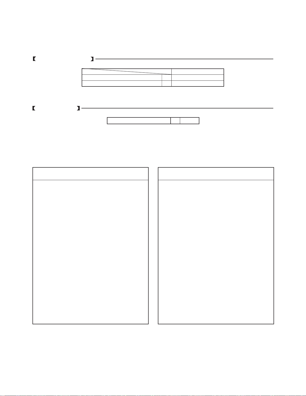
4. Before returning the set to the customer, always perform
anACleakagecurrentcheckontheexposed metallic parts
of the cabinet, such as antennas, terminals, screwheads,
metal overlays, control shafts etc. to be sure the set is
safe to operate without danger of electrical shock. Plug
the AC line cord directly into a 120V AC outlet (do not use
a line isolation transformer during this check). Use an AC
voltmeter having 5000 ohms per volt or more sensitivity in
the following manner:
AC VOLTMETER
0.15µF
Good earth ground
such as a water
pipe, conduit, etc.
Place this probe on
each exposed
metallic part.
1500 ohm
10 watt
PRODUCT SAFETY NOTICE
Many electrical and mechanical parts in this chassis have special safety-related characteristics.These characteristics are
often passed unnoticed by a visual inspection and the protection afforded by them cannot necessarily be obtained by using
replacement components rated for higher voltage, wattage, etc. Replacement parts which have these special safety char-
acteristics are identified in this manual and its supplements; electrical components having such features are identified by
the international hazard symbols on the schematic diagram and the parts list.
Before replacing any of these components, read the parts list in this manual carefully.The use of substitute replacement
parts which do not have the same safety characteristics as specified in the parts list may create shock, fire, X-ray
radiation or other hazards.

– 4 –
GENERAL ADJUSTMENTSSPECIFIC INFORMATIONS
WARNING: BEFORE SERVICING THIS CHASSIS, READ THE “X-RAY RADIATION PRECAUTION”, “SAFETY PRECAU-
TION” AND “PRODUCT SAFETY NOTICE” ON PAGE 3 OF THIS MANUAL.
SET-UP ADJUSTMENT
SET-UP ADJUSTMENT FOR 13", 14", 19", 20".
■The following adjustments should be made when a complete realignment is required or a new picture tube is installed.
Perform the adjustments in order as follows :
1. Color Purity
2. Convergence
3. White Balance
Note: The PURITY/CONVERGENCE MAGNET assembly and rubber wedges need mechanical positioning.
Refer to figure 1.
Mounting position of the purity magnet assembly should fit to same position as old one because slightly difference to
the position depend on a kind of tube.
*There are no adjustment of purity and convergence in some picture tube (Unified with purity magnet)
GLASS CLOTH
TAPES
DEFLECTION
YOKE
TEMPORARY
MOUNTING
RUBBER WEDGE
ADHESIVE
DEFLECTION
YOKE
PURITY/
CONVERGENCE
MAGNET ASS'Y
14mm(13", 14")
19mm(19", 20")
Figure 1.
COLOR PURITY ADJUSTMENT
NOTE : Beforeattemptinganypurityadjustments,thereceiver
should be operated for at least fifteen minutes.
1. Demagnetizethepicturetubeandcabinetusing a degauss-
ing coil.
2. Set the brightness and contrast to maximum.
3. Use a green raster from among the built-in test signals.
4. Loosen the clamp screw holding the yoke and slide the
yoke backward or forward to provide vertical green belt
(zone) in the picture screen.
5. Remove the Rubber Wedges.
6. Rotate and spread the tabs of the purity magnet (See fig-
ure 2.) around the neck of the picture tube until the green
belt is in the center of the screen. At the same time, enter
the raster vertically.
7. Slowly move the yoke forward or backward until a uniform
green screen is obtained.Tighten the clamp screw of the
yoke temporarily.
8. Check the purity of the red and blue raster.

– 5 –
GENERAL ADJUSTMENTSSPECIFIC INFORMATIONS
CONVERGENCE ADJUSTMENTS
NOTE: Before attempting any convergence adjustments, the
receiver should be operated for at least fifteen min-
utes.
■CENTER CONVERGENCE ADJUSTMENT
1. Use the cross-dot pattern from among the built-in test sig-
nals.
2. Set the brightness and contrast for well defined pattern.
3. Adjust two tabs of the 4-Pole Magnets to change the an-
gle between them (See figure 2.) and superimpose red
and blue vertical lines in the center area of the picture
screen.
4. Turn the both tabs at the same time keeping the angle
constant to superimpose red and blue horizontal lines at
the center of the screen.
5. Adjust two tabs of 6-Pole Magnets to superimpose red/
blue line and green one. Adjusting the angle affects the
vertical lines and rotating both magnets affects the hori-
zontal lines.
6. Repeat adjustments 3, 4, 5 keeping in mind red, green
and blue movement, because 4-Pole Magnets and 6-Pole
Magnetshave mutual interaction and makedot movement
complex.
■CIRCUMFERENCE CONVERGENCE ADJUSTMENT
1. Loosen the clamping screw of deflection yoke slightly to
allow the yoke to tilt.
2. Temporarily put a wedge as shown in figure 1. (Do not
remove cover paper on adhesive part of the wedge.)
3. Tilt front of the deflection yoke up or down to obtain better
convergence in circumference. (See figure 3.) Push the
mounted wedge into the space between picture tube and
the yoke to fix the yoke temporarily.
4. Put other wedge into bottom space and remove the cover
paper to stick.
5. Tilt front of the yoke right or left to obtain better conver-
gence in circumference. (See figure 3.)
6. Keep the yoke position and put another wedge in either
upper space. Remove cover paper and stick the wedge
on picture tube to fix the yoke.
7. Detach the temporarily mounted wedge and put it in an-
other upper space. Stick it on picture tube to fix the yoke.
8. After fixing three wedges, recheck overall convergence.
Tighten the screw firmly to fix the yoke and check the yoke
is firm.
9. Stick three adhesive tapes on wedges as shown in figure
1.
4-POLE
MAGNETS
PURITY
MAGNETS
6-POLE
MAGNETS ADJUST THE ANGLE
(VERTICAL LINES) FIXED
ROTATE TWO TABS
AT THE SAME TIME
(HORIZONTAL LINES)
CONVERGENCE MAGNET ASSEMBLY ADJUSTMENT OF MAGNETS
Figure 2.
BLU RED
BLU
RED
RED/BLU GRN
RED/BLU
GRN
B
G
R
R
G
B
BGR
RGB
BGR
RGB
R
G
B
B
G
R
4-POLE MAGNETS MOVEMENT
INCLINE THE YOKE UP (OR DOWN)
6-POLE MAGNETS MOVEMENT
Center Convergence by Convergence Magnets
Circumference Convergence by DEF Yoke
INCLINE THE YOKE RIGHT (OR LEFT)
Figure 3. Dot Movement Pattern

– 6 –
GENERAL ADJUSTMENTSSPECIFIC INFORMATIONS
WARNING: BEFORE SERVICING THIS CHASSIS, READ THE “X-RAY RADIATION PRECAUTION”, “SAFETY PRECAU-
TION” AND “PRODUCT SAFETY NOTICE” ON PAGE 3 OF THIS MANUAL.
COLOR PURITY ADJUSTMENT
NOTE : Before attempting any purity adjustments, the
receiver should be operated for at least fifteen
minutes.
1. Evenly degauss the entire screen.
2. Set the CONTRAST and BRIGHTNESS Controls to
the maximum.
3. Display built-in green raster using the TEST SIGNAL
SELECTION function.
4. Loosen the clamp screw holding the deflection yoke
(and remove the Rubber Wedges).
5. Slide the yoke forward or backward to provide vertical
green belt (zone) in the picture screen.
6. Rotate and spread the tabs of the purity magnet (See
figure 4.) around the neck of the picture tube until the
green belt is in the center of the screen. At the same
time, center the raster vertically by adjusting the mag-
net as shown below.
7. Move the yoke slowly forward or backward until a uni-
form greenscreenisobtained.Tighten the clamp screw
of the yoke temporarily.
8. Check the purity of the red and blue raster.
9. Put four wedges into the space between the picture
tube and the yoke to hold the yoke in the adjusted
position. (See figure 2.)
Donottilttheyokebyexcessiveinsertionof the wedge.
10. Remove cover paper of wedge and stick wedges on
the tube to fix the yoke in the adjusted position.
Fix the wedges with glass cloth tapes.
Green Belt
Figure 2.
Figure 1.
SET-UP ADJUSTMENT FOR 35", 36".
■The following adjustments should be made when a complete realignment is required or a new picture tube is installed.
Perform the adjustments in order as follows :
1. Color Purity
2. Convergence
3. White Balance
Note: The PURITY/CONVERGENCE MAGNET assembly and rubber wedges need mechanical positioning.
Refer to figure 1.
Mounting position of the purity magnet assembly should fit to same position as old one because slightly difference to
the position depend on a kind of tube.
*There are no adjustment of purity and convergence in some picture tube (Unified with purity magnet)
DEFLECTION YOKE
Xv Coil
PURITY/
CONV.
MAGNET
RUBBER WEDGES
Adhesive
DEFLECTION
YOKE
1-5/8"

– 7 –
GENERAL ADJUSTMENTSSPECIFIC INFORMATIONS
CONVERGENCE ADJUSTMENTS
NOTE: Before attempting any convergence adjustments,
the receiver should be operated for at least fifteen
minutes.
■CENTER CONVERGENCE ADJUSTMENT
1. Display built-in cross-dot pattern using theTEST SIG-
NAL SELECTION function.
2. Adjust the BRIGHTNESS and CONTRAST Controls
for well defined pattern.
3. Loosen the tightening ring and adjust two tabs of the
4-Pole Magnets to change the angle between them
(See figure 4.) and superimpose red and blue vertical
lines in the center area of the picture screen.
(See figure 3.)
4. Turn the both tabs at the same time keeping the con-
stant angle to superimpose red and blue horizontal
lines at the centre of the screen. (See figure 3.)
5. Adjusttwotabsof6-PoleMagnetstosuperimposered/
blue line with green one. Adjusting the angle affects
the vertical lines and rotating both magnets affects the
horizontal lines.
6. Repeatadjustments 3, 4, 5 keeping in mind red, green
and blue movement, because 4-Pole Magnets and 6-
Pole magnets interact and make dot movement com-
plex.
7. After completing the “CENTER CONVERGENCE AD-
JUSTMENT” tighten the tightening ring to fix the mag-
nets.
Figure 3.
■Xv COIL ADJUSTMENT
Adjust the Xv coil (on the deflection yoke) to correct
misconvergence at both sides on screen.
Use a hexagonal tip stick (plastic) to adjust the core of
coil.
BLU
BLU RED
RED
6-POLE MAGNETS
MOVEMENT
4-POLE MAGNETS
MOVEMENT
RED/BLUE
RED/BLUE GRN
GRN
Center Convergence by Convergence Magnets
R
B
B
R
B
R
R
B
Clockwise Adjustment Counterclockwise Adjustment
XvCross Pattern View
■SCREEN-CORNER CONVERGENCE
When the misconvergence is still evident on corners even
though the above adjustment is done, use the ferrite sheet
(Part No. 23993622) to correct misconvergence.
1. Put ferrite sheets into the space under the yoke.
Decide such position that misconvergence becomes
minimum,watchingpicture screen.(See figurebelow.)
2. Remove cover paper of ferrite sheet to stick it in the
placeon the tube. Put adhesive tapesonferrite sheets
to fix.
Figure 4.
Ferrite
Sheets Ferrite
Sheets
For correcting misconvergence
on the position A
A
4-POLE
MAGNETS
6-POLE
MAGNETS
PURITY
MAGNETS
PURITY/CONVERGENCE
MAGNETS
ADJUSTTHE ANGLE
(VERTICAL LINES) FIXED
ROTATE TWO TABS
AT THE SAME TIME
(HORIZONTAL LINES)
ADJUSTMENT OF MAGNETS

– 8 –
GENERAL ADJUSTMENTSSPECIFIC INFORMATIONS
SERVICE MODE
1. ENTERING TO SERVICE MODE
MUTE
S
(Service mode display)
3) While pressing the MUTE button,
press MENU button on TV set.
2) Press MUTE button
again to keep pressing.
1) Press MUTE button once
on Remote Control.
2. DISPLAYINGTHE ADJUSTMENT MENU
1) Press MENU button on TV.
Adjustment mode
Press
Press
Service mode
Item
Data
S
3. KEY FUNCTION IN THE SERVICE MODE
The following key entry during display of adjustment menu provides special functions.
Test signal selection : TV (ANT)/VIDEO button (on Remote)
Selection of the adjustment items : Channel s/t(on TV or Remote)
Change of the data value : Volume s/t(on TV or Remote)
Adjustment menu mode ON/OFF : MENU button (on TV)
Initialization of the memory (QA02) : RECALL+Channel (s) button on TV
Initialization of the self diagnostic data: RECALL+Channel (t) button on TV
“RCUT” selection : 1 button
“GCUT” selection : 2 button
“BCUT” selection : 3 button
“CNTX” selection : 4 button
“COLC” selection : 5 button
“TNTC” selection : 6 button
Test audio signal ON/OFF (1kHz) : 8 button
Self diagnostic display ON/OFF : 9 button
A single horizontal line ON/OFF: 100 button

– 9 –
GENERAL ADJUSTMENTSSPECIFIC INFORMATIONS
4. SELECTING THE ADJUSTING ITEMS
1) Every pressing of CHANNEL sbutton in the service mode changes the adjustment items in the order of table-2.
(tbutton for reverse order)
Refer to table-2 for preset data of adjustment mode.
(See SETTING & ADJUSTING DATA on page 15)
5. ADJUSTING THE DATA
1) Pressing of VOLUME sor tbutton will change the value of data in the range from 00H to FFH.The variable range
depends on the adjusting item.
6. EXIT FROM SERVICE MODE
1) Pressing POWER button to turn off the TV once.
■INITIALIZATION OF MEMORY DATA OF QA02
After replacing QA02, the following initialization is required.
1. Enter the service mode, then select any register item.
2. Press and hold the RECALL button on the Remote, then press the CHANNEL sbutton on theTV.The initialization of QA02
has been complated.
3. Check the picture carefully. If necessary, adjust any adjustment item above.
Perform “Programming Channel Memory”.
CAUTION: Never attempt to initialize the data unless QA02 has been replaced.
7. TEST SIGNAL SELECTION
1) Every pressing of TV/VIDEO button on the Remote Control in the Service mode changes the built-in test patterns
on screen in the following order.
Normal picture Black cross-bar
on green raster
Red raster H signal (black)
H signal (white)
Green raster
Blue raster White cross-dot
All black Black cross-dot
All white White cross-hatch
Black cross-hatch
White and black
Black cross-bar
White cross-bar
Signals Picture
• Red raster
• Green raster
• Blue raster
• All Black
• All White
• Black & White
• Black cross-hatch
• White cross-hatch
• Black cross-dot
• White cross-dot
• Black cross-bar
• White cross-bar
• Black cross-bar
on green raster
• H signal (white)
• H signal (black)
2) Press “8” button while any built-in test pattern to on the screen to
output the 1 kHz sound. Press the button again to cut off the sound.
Note: If the video cable is connected to the VIDEO1 INPUT jack, the
built-in pattern signals are not displayed.
*The signals marked with are not usable to display in the Test signal for some model.

– 10 –
GENERAL ADJUSTMENTSSPECIFIC INFORMATIONS
8. SELF DIAGNOSTIC FUNCTION (MTS Model)
1) Press “9” button on Remote Control during display of adjustment menu in the service mode.
The diagnosis will begin to check if interface among IC’s are executed properly.
2) During diagnosis, the following displays are shown.
SELF CHECK
NO. 23XXXXXX
POWER : 000
BUS LINE : OK
BUS CONT : OK
BLOCK : UV V1 V2
or QV01 QV01S
SYNC
1
2
3
4
5
1Part number of microprocessor (QA01)
2Operation number of protection circuit (current limiter) . . . . “000” is normal.
3BUS line check “OK” ................... Normal
“SCL-GND” or “NG” .......... SCL-GND short circuit
“SDA-GND” or “NG”.......... SDA-GND short circuit
“SCL-SDA” or “NG”........... SCL-SDA short circuit
4BUS line ACK (acknowledge) check
“OK” ..................... Normal
Display of Location Number . . . . NG
(Display example)
“QA02 NG”, “H001 NG”, “Q501 NG” etc.
Note: The indication of failure place is only one place though failure places are plural. When
repair of a failure place finishes, the next failure place is indicated. (The order of priority of
indication is left side.)
5Sync. signal check Green display..... Normal
Cyan display ......No check
Red display ........NG
UV........... TV mode
V1 ........... VIDEO 1 mode
V2 ........... VIDEO 2 mode
9. SELF DIAGNOSTIC FUNCTION (Monaural Model)
1) Press “9” button on Remote Control during display of adjustment menu in the service mode.
The diagnosis will begin to check if interface among IC’s are executed properly.
2) During diagnosis, the following displays are shown.
*The items marked with are not usable to display in the SELF DIAGNOSTIC FUNCTION for some model.
NO. 23XXXXXX
SELF CHECK
POWER : 000
BUS : OK
NO ACK :
Part number of microprocessor (QA01)
Operation number of protecting circuit ----"000" is normal.
BUS line check ----"OK" is normal.
"[blank]" is normal.

– 11 –
GENERAL ADJUSTMENTSSPECIFIC INFORMATIONS
DESIGN MODE
1. ENTERING TO DESIGN MODE
ITEM
DATA
S D Press
(Design mode) (Adjustment mode)
Press
3) Press MENU button on TV.
2) While pressing RECALL button on.
Remote and press MENU button on TV.
1) Select the Service mode.
2. SELECTINGTHE ADJUSTING ITEMS
Every pressing of CHANNEL tbutton in the design mode changes the adjustment items in the order of table-3.
(sbutton for reverse order)
Refer to table-3 for data of design mode.
(See SETTING & ADJUSTING DATA on page 15)
3. ADJUSTINGTHE DATA
Pressing of VOLUME sor tbutton will change the value of data.
When QA02 is initialized, items “OPT0” and “OPT1” of DESIGN MODE are set to the data of the representative model of this
chassis family.
Therefore, because ON-SCREEN specification remains in the state of the representative of model. This model is required to
reset the data of items “OPT0” and “OPT1”.

– 12 –
GENERAL ADJUSTMENTSSPECIFIC INFORMATIONS
ELECTRICAL ADJUSTMENTS
Vertical retrace line
1. Enter the service mode, then select any register item.
2. Press the TV/VIDEO button on the Remote until the black cross-bar pattern
appears on the screen.
3. Adjust the FOCUS control (on T461) for well defined scanning lines on the
picture screen.
FOCUS VR ADJ.
SUB-BRIGHTNESS
(BRTC) 1. Constrict the picture height until the
vertical retrace line appears adjusting the
HEIGHT control on the MAIN board.
2. Adjust the CONTRAST to the minimum
and BRIGHTNESS to the center.
3. Enter the service mode, then select
“BRTC” register.
4. Adjust the data value so the belt of
vertical retrace line just disappear.
5. Adjust the CONTRAST for the desired
contrast.
6. Adjust the HEIGHT control.
SUB-COLOR
(COLC)
SUB-TINT
(TNTC)
1. Receive color-bar signal from color-bar generator.
2. Adjust the BRIGHTNESS and CONTRAST to the center (RESET status).
3. Connect oscilloscope pin 23 of Q501 on the MAIN board.
4. Enter the service mode, then select “COLC”.
5. Temporarily adjust the data value to
achieve about 1V0-p of blue bar.
6. Select “TNTC” register.
7. Adjust the data value to obtain the blue
bar to magenta bar ratio of 3:2 as
shown.
8. Select “COLC” register.
9. Adjust the data value to achieve 1.25V0-p
of blue bar on scope.
10. Check the picture with off-air signal.
HORIZONTAL POSITION
(HPOS)
VERTICAL POSITION
(VPOS)
1. Call up the adjustment mode display, then select the Item HPOS or VPOS.
2. Press the TV/VIDEO button until the white cross-bar
or black cross-bar pattern appears on the screen.
3. Adjust the HORIZONTAL and VERTICAL position
alternately by pressing the VOLUME sor tbutton
for proper picture position.
4. Check the picture with off-air signal.
ITEM ADJUSTMENT PROCEDURE
0
Blue
Magenta
23 (1.25V
0-P
)
HEIGHT
(HIT) 1. Call up the adjustment mode display, then select the Item HIT.
2. Press the VOLUME sor tbutton to get the picture so the top of raster begins
to lack.
3. Press the VOLUME sbutton to advance the data by 8 steps.
Note : Check the vertical picture position is correct.

– 13 –
GENERAL ADJUSTMENTSSPECIFIC INFORMATIONS
ITEM ADJUSTMENT PROCEDURE
WHITE BALANCE
RCUT
GCUT
BCUT
GDRV
BDRV
1. Adjust the CONTRAST control to the center, and BRIGHTNESS control to the
maximum.
2. Call up the adjustment mode display, and press the TV/VIDEO button until the
white and black pattern appears on the screen.
3. Adjust the following address with the CHANNEL s/tand VOLUME s/t
buttons.
4. Press “100” button on the Remote Control to display a single horizontal line on
the screen.
5. Turn the SCREEN control (FBT) fully counterclockwise and gradually rotate
clockwise until the first horizontal line appears slightly on the screen.
6. Press “100” button to display the normal picture.
7. Adjust the remaining two “?CUT” Item (CHANNEL s/t→ 100 →VOLUME s/t
in order) to obtain the slightly lighted horizontal line in the same levels of three
(red, green, blue) colors.The line should be white if the adjustments are proper.
Bright area
Adjust "GDRV" or "BDRV" to be white.
Dark area
Fine adjust "RCUT", "GCUT" or "BCUT" to be black.
RCUT Data : 30H
GCUT Data : 30H
BCUT
Item :
Item :
Item :
Item :
Item :
Data : 30H
GDRV Data : 80H
BDRV Data : 80H

– 14 –
GENERAL ADJUSTMENTSSPECIFIC INFORMATIONS
CIRCUIT CHECKS
Troubleshooting Guide for Fail Safe Circuit
Check that the set returns to normal operation when pin 12
of Z801(or emitter of Q472) is grounded with jumper wire.
Check the voltage across
Capacitor C471 is
approximately (c) volts.
Refer to table –4 for
FBT detection voltage (c).
Faulty power
circuit or hori-
zontal circuit.
Defective Fail Safe Circuit
(See SETTING & ADJUSTING
DATA on page15)
YES NO
NO
YES
HIGHVOLTAGE CHECK
CAUTION: There is no HIGH VOLTAGE ADJUSTMENT on
this chassis. Checking should be done following the steps
below.
1. Connect an accurate high voltage meter to the second an-
ode of the picture tube.
2. Turn on the receiver. Set the BRIGHTNESS and CON-
TRAST controls to minimum (zero beam current).
3. High voltage must be measured below (B) kV.
Refer to table-1 for high voltage (B).
(See SETTING & ADJUSTING DATA on page 15)
4. Vary the BRIGHTNESS control to both extremestobesure
the high voltage does not exceed the limit under any con-
ditions.
FS CIRCUIT CHECK
The Fail Safe (FS) circuit check is indispensable for the final
check in servicing. Checking should be done following the
steps below.
1. Turn the receiver on and press the RESET button.
2. Temporarily short TP-(R) and TP-(X) with a jumper wire.
Raster and sound will disappear.
3. The receiver must remain in this state even after removing
the jumper wire.This is the evidence that the FS circuit is
functioning properly.
4. To obtain a picture again, temporarily turn the receiver off
and allow the FS circuit more than 5 seconds to reset.
Then turn the power switch on to produce a normal pic-
ture.

– 15 –
GENERAL ADJUSTMENTSSPECIFIC INFORMATIONS
SETTING & ADJUSTING DATA
RCUT
GCUT
BCUT
GDRV
BDRV
CNTX
BRTC
COLC
TNTC
HPOS
VPOS
HIT
Item
RED CUT-OFF
GREEN CUT-OFF
BLUE CUT-OFF
GREEN DRIVE
BLUE DRIVE
SUB-CONTRAST
SUB-BRIGHTNESS
SUB-COLOR
SUB-TINT
HORIZONRAL POSITION
VERTICAL POSITION
HEIGHT
Name of adjustment Reference Data
30H
30H
30H
80H
80H
50H
38H
2CH
42H
19H
02H
1EH
✩
✩
✩
✩
✩
✩
✩
✩
✩
✩
✩
SERVICE MODE
ADJUSTING ITEMS AND DATAS INTHE SERVICE MODE:
Table-2
CHAPTER 2 SPECIFIC INFORMATIONS
SAFETY INSTRUCTIONS
✩These adjustments may be required when replacing QA02 and Q501.
19"
HIGH VOLTAGE AT ZERO BEAM: (A) 24.7 kV
MAX HIGH VOLTAGE: (B) 26.1 kV
Table-1
DESIGN MODE
ADJUSTING ITEMS AND DATAS INTHE DESIGN MODE:
Data
Item Name of adjustment Preset Data Remarks
*There are no adjusting item in the DESIGN MODE.
Table-3
CIRCUIT CHECKS
FBT DETECTION VOLTAGE (C) 19"
22.03 V
Table-4

– 16 –
GENERAL ADJUSTMENTSSPECIFIC INFORMATIONS
LOCATION OF CONTROLS
1 2 3
4 5 6
7 8 9
100 0
CH RTN
TV/VIDEO
POWER
RECALL MUTE
MENU EXIT
CH
VOL
CH
VOL
VOLUMEMENU POWER
CHANNEL
Remote sensor
TV/VIDEO button
VOLUME T/Sbutton
(Menu T/Sbutton) CHANNEL s/tbuttons
(Menu s/tbuttons)
MENU button
RECALL button
POWER button
Channel Number button
RTN button
MUTE button
EXIT button
Front
Remote Control

– 17 –
GENERAL ADJUSTMENTSSPECIFIC INFORMATIONS
PROGRAMMING CHANNEL MEMORY
The channel memory is the list of TV channel numbers your TV will stop on when you press the CHANNEL sor tbutton.
First, use theTV/CABLE and CH PROGRAM functions to preset all active channels in your area.
If necessary, arrange the preset channels with the ADD/ERASE functions so that you can tune into only desired channels.
TV/CABLE function
1Press POWER, to turn on the TV.
2PressMENU(thensort)repeatedlyuntil "TV/CABLE"in
the Set up menu is displayed in purple.
3Press;(<)or :(>) until themodethatcorrespondstoyour
TV signal system is displayed in purple.
CH PROGRAM function
1Press MENU (then sor t) repeatedly until "CH PRO-
GRAM" in the Set up menu is displayed in purple.
2Press ;(<) or :(>) to start channel programming.
TheTVwillautomaticallycyclethroughalltheTVorCABLE
channels depending on the mode selected, and store
active channels in the channel memory.
3When channel programming is complete, you will see the
message to the right.
4Press CHANNEL sor tto make sure the channel pro-
gramming has been done properly.
ADD/ERASE function
After performing the CH PROGRAM function, you can add
or erase specific channels.
1Selectthechannelyouwanttoeraseusingthe CHANNEL
sor tbutton, or select the channel you want to add using
the Channel Number buttons.
2PressMENU(thensort)repeatedly until “ADD/ERASE”
in the Set up menu is displayed in purple.
3Press ;(<) or :(>) :
To erase the channel
Pressthebuttonuntil“Erase”isdisplayedinpurpleindicat-
ing that the channel has been erased from the memory.
To add the channel
Press the button until “ADD” is displayed in purple indicat-
ing that the channel has been memorized.
4Repeat steps 1 to 3 for other channels.
You have now completed the channel programming.
Table of contents
Other Toshiba TV manuals

Toshiba
Toshiba 43VJ22P User manual

Toshiba
Toshiba 26HF14SVM User manual

Toshiba
Toshiba 27A41C User manual

Toshiba
Toshiba 13A24 User manual

Toshiba
Toshiba 50A60 User manual

Toshiba
Toshiba 19A26C User manual

Toshiba
Toshiba 34HDX82 User manual

Toshiba
Toshiba 30HFX85 User manual

Toshiba
Toshiba L243*DB User manual

Toshiba
Toshiba 49L3753DB User manual

Toshiba
Toshiba MW24F11 User manual

Toshiba
Toshiba ColorStream TP43H60 User manual

Toshiba
Toshiba MV19K2 User manual

Toshiba
Toshiba CF35F40 User manual

Toshiba
Toshiba Regza XV55 Series User manual

Toshiba
Toshiba 21N21B2 User manual

Toshiba
Toshiba 42WLT58 Series User manual

Toshiba
Toshiba 14AR22 User manual

Toshiba
Toshiba 29AX9UM User manual

Toshiba
Toshiba 36HF71 User manual