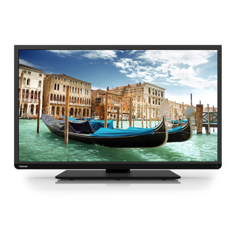
Toshiba 32WL66Z User manual

SERVICE MANUAL
Color Television
32WL66Z Ver.1
Thismodelis classified as a green product
(*1), as indicated by the underlined serialnumber.
ThisService Manualdescribes replacementpartsforthe green product. When repairing this
green product, usethe part(s)described in this manualand lead-free solder (*2).
For(*1)and (*2), referto GREENPRODUCTPROCUREMENT and LEAD-FREE
SOLDER.
©TOSHIBACORPORATION
Page
1
of
1

SAFETY INSTRUCTION
Handling theLCDModule
Safety Precaution
In the eventthatthe screen is damaged orthe liquid crystal(fluid)leaks, do notbreathein or
drink this fluid.
Also, nevertouch this fluid. Such actions could cause toxicity orskin irritation. Ifthis fluid
should enterthe mouth, rinse the mouth thoroughly with water. Ifthe fluid should contactthe
skin orclothing, wipe offwith alcohol, etc., and rinse thoroughly with water. Ifthe fluid
should enterthe eyes, immediately rinsethe eyes thoroughly with running water.
Precautions forHandlingthe LCD Module
The LCDmodule can easily bedamaged during disassembly orreassembly;therefore,
always observe thefollowing precautions when handling the module.
1.
When attaching the LCDmodule to the LCDcover, position itappropriately and fasten
atthe position wherethe display can beviewed mostconveniently.
2.Carefully align the holes atallfourcorners ofthe LCDmodulewith the corresponding
holes inthe LCDcoverand fasten with screws. Do notstrongly push on the module
because any impactcan adversely affectthe performance. Also use caution when
handling the polarized screen becauseitcan easily be damaged.
CAUTION:Themetaledgesofthe LCDmoduleare sharp,handleit with
care.
Page
1
of
4
Handling theLCD Module

3.Ifthepanelsurface becomes soiled, wipe with cotton ora softcloth. Ifthis doesnot
remove the soiling, breatheon the surface and then wipe again.
Ifthepanelsurface is extremely solied, use aCRT cleaneras a cleaner. Wipe offthe
panelsurface by drop the cleaneron thecloth. Do notdrop the cleaneron thepanel.
Pay attention notto scratch the panelsurface.
4.Leaving waterorotherfluids on the panelscreen foran extended period oftimecan
resultin discolorationorstripes. Immediately remove any type offluid fromthe screen.
5.Glass is used in the panel, so do notdrop orstrikewith hard objects. Such actions can
damage the panel.
Page
2
of
4
Handling theLCD Module

6.CMOS-LSIcircuitry is used in the LCDmodule, so avoid damage dueto static
electricity. When handling the module, use a wristground oranchorground.
7.Do notexpose theLCD module to directsunlightorstrongultravioletrays foran
extended periodoftime.
8.Do notstore the LCDmodule belowthe temperature conditions described in the
specifications. Failure to do so could resultin freezing ofthe liquid crystaldue to cold
airorlossofresilience orotherdamage.
9.Do notdisassemble theLCDmodule. Such actionscould resultin improperoperation.
Page
3
of
4
Handling theLCD Module

10.When transporting the LCDmodule, do notuse packing containing epoxy resin
(amine)orsilicon resin (alcoholoroxim). The gas generated by these materialscan
cause loss ofpolarity.
Page
4
of
4
Handling theLCD Module

PCB LAYOUT
Page
1
of
1

RF
N
o
n
6
5
6
Y
C
b
C
r
1
6
b
i
t
B
t
6
0
1
8
B
i
t
H
D
,
V
D
,
C
L
K
U
A
R
T
R
E
Q
HDMI
CORTEZ Plus
Analog
Front
End
(16port)
Video
Decoder
MUX
VBIData
Processor
DCDi
MADi
Scaling
BEP
OSD
LVD
S
Micro-
processor
IRI/F AD
C
GPI
O
Digital
InputA
Digital
InputB
2nd
Channel
Process
Cortez
Regulator
EEPROM
DDRRAM
FLASHROM
I
2
C
I
2
C
SIGNALBOARD
I
2
C
FLI8538
Input
Terminal
(Video)
CVBS
S-VIDEO
YCbCr
PCIN
+LowB
POWERBOARD
SoundAMP
ACINPUT&
Power
AVBOARD
TIF
PANEL
PANELI/F
Standby
uCON
HDMI
MTS+
APRO
MSP
PLL
VOC
SPEAKER
DACAMP
HP_AMP
Headphone
Input
Terminal
(Audio)
CVBS(L/R)
S-VIDEO(L/R)
YCbCr(L/R)
PC_IN(L/R) SW

SCHEMATIC DIAGRAM
Precaution
Note:
1.RESISTOR
Resistance isshownin ohm[K=1,000, M=1,000,000]. Allresistors are 1/6 W and 5 %
tolerance carbon resistor, unless otherwisenoted as thefollowing marks.
2.CAPACITOR
Unless otherwise noted in schematic, allcapacitorvalues less than 1 areexpressed in
µF, and thevalues more than 1 in pF.
WARNING: BEFORESERVICINGTHISCHASSIS,READ THE "X-RAY
RADIATIONPRECAUTION"FORDIRECTVIEWCTVONLY,"SAFETY
PRECAUTION"AND"PRODUCTSAFETYNOTICE"OFTHISMANUAL.
CAUTION:Theinternationalhazard symbols" "intheschematicdiagram
and the partslistdesignatecomponentswhichhave specialcharacteristics
importantfor safetyand
shouldbe replaced onlywithtypesidenticaltothose inthe originalcircuit
or specified inthepartslist.
The mountingpositionofreplacementsistobe identicalwithoriginals.
Before replacinganyof thesecomponents,read carefullytheSAFETY
PRECAUTIONand PRODUCTSAFETYNOTICE.
Donot degrade thesafetyofthe receiverthrough improper servicing.
1/2R
:
MetalorMetaloxide of1/2 watt
1/2S
:
Carbon composition of1/2 watt
1RF
:
Fuse resistorof1 watt
10 W
:
Cementof10 watt
K
:
±10 %
G
:
±2 %
F
:
±1 %
Page
1
of
2

Allcapacitors are ceramic 50 V, unless otherwisenoted as thefollowing marks.
3.The parts indicated with " "have specialcharacteristics, and should bereplaced with
identicalparts only.
4.Voltages read with DIGITAL MULTI-METERfrompointindicated to chassis ground,
using a colorbarsignalwith allcontrols atnormal, line voltage atnominalACvolts.
5.Waveforms are taken receiving colorbarsignalwith enough sensitivity.
6.Voltage readingshown are nominalvalues and may vary ±20 %exceptH.V.
=
Electrolytic capacitor
= Mylarcapacitor
Page
2
of
2

IMPORTANT NOTICE
WARNING:
Youare requested thatyoushallnot modifyoralter theinformationor data
provided hereinwithout prior writtenconsentbyToshiba.Toshiba shall not
be liabletoanybody for any damages,losses,expenses or costs,ifany,
incurred inconnection withor asaresultofsuch modification oralteration.
THE INFORMATIONORDATAHEREINSHALLBEPROVIDED"ASIS"
WITHOUTANYWARRANTYOFANYKIND, EITHEREXPRESS ORIMPLIED
WARRANTYOFMERCHANTABILITYANDFITNESSFORAPARTICULAR
PURPOSE.
Toshibashallnot be liablefor anydamages,losses,expensesorcosts,if
any,incurred inconnectionwithoras aresultofuse ofanyinformationor
dataprovided herein.
Page
1
of
1

GREEN PRODUCT PROCUREMENT
The ECis actively promoting the WEEE &RoHS Directivesthatdefine standards for
recycling and reuseofWaste Electricaland Electronic Equipmentand forthe Restriction of
the use ofcertain HazardousSubstances. FromJuly 1, 2006, the RoHS Directive will
prohibitany marketing ofnewproducts containing the restricted substances.
Increasing attention is given to issues related to the globalenvironmental. Toshiba
Corporation recognizes environmentalprotection as a key managementtasks, and is doing its
utmostto enhance and improve the quality and scopeofits environmentalactivities. In line
with this, Toshibaproactively promotes GreenProcurement, and seeks topurchase and use
products, parts and materials thathave lowenvironmentalimpacts.
Green procurementofparts isnotonly confined to manufacture. The same green parts used
inmanufacture mustalso beused asreplacementparts.
Page
1
of
1

LEAD-FREE SOLDER
Thisproductis manufactured using lead-freesolderas apartofa movementwithinthe
consumerproducts industry atlarge to beenvironmentally responsible. Lead-
freesoldermust
be used in the servicing and repairofthisproduct.
The melting temperatureoflead-freesolderishigherthan thatofleaded solderby 86 F to
104 F (30 Cto40 C). Useofa soldering iron designed forlead-based solders to repair
productmade with lead
-
free soldermayresultin damage to the componentand orPCB being
soldered. Greatcareshould bemadeto ensure high-quality soldering when servicing this
productespecially when soldering large components, through
-hole pins, and on PCBs asthe
levelofheatrequired to meltlead-free solderishigh.
WARNING: Thisproductismanufacturedusing lead free solder.
DONOTUSELEADBASEDSOLDER TOREPAIRTHISPRODUCT!
Page
1
of
1

SAFETY INSTRUCTION
SafetyPrecaution
1.An isolation transformershould be connected in the powerlinebetween the receiver
and the ACline before any service is performed on the receiver.
2.Always disconnectthe powerplug before any disassembling ofthe product. It may
resultin electricalshock.
3.When replacing a chassisin thecabinet, always be certain thatallthe protective
devices are putback in place, such as nonmetallic controlknobs, insulating covers,
shields, isolation resistor-capacitornetwork, etc.
4.
Always keep tools, componentsoftheproduct, etc away fromthe children, These items
may causeinjury to children.
5.Depending on the model, use an isolation transformerorwearsuitable gloves when
servicing with the poweron, and disconnectthepowerplug to avoid electricalshock
when replacing parts. In somecases, alternating currentis also impressed in the
chassis, so electricalshock ispossible ifthe chassis is contacted withthe poweron.
6.Always usethe replacementpartsspecified fortheparticularmodelwhen making
repairs. The parts used in products requirespecialsafety characteristicssuch as
WARNING: BEFORESERVICINGTHISCHASSIS,READ THE "SAFETY
PRECAUTION"AND"PRODUCTSAFETYNOTICE"INSTRUCTIONSBELOW.
WARNING: SERVICINGSHOULDNOTBEATTEMPTEDBYANYONE
UNFAMILIARWITHTHE NECESSARYPRECAUTIONSON THISRECEIVER.
THE FOLLOWINGARE THE NECESSARYPRECAUTIONSTOBEOBSERVED
BEFORESERVICINGTHISCHASSIS.
Page
1
of
4
SAFETYINSTRUCTION[LCD]ASIA, EU

inflammability, voltage resistance, etc. therefore, use only replacementparts thathave
these same characteristics. Use only the specifiedparts when the mark isindicated
in the circuitdiagramorparts list.
7.Parts mounting and routingdressing ofwiringsshould bethe sameas thatused
originally. Forsafety purposes, insulating materials such as isolation tube ortape are
sometimes used and printed circuitboardsare sometimes mounted floating. Also make
sure thatwirings is routed and clamped to avoid parts thatgenerate heatand which use
high voltage. Always followthe manufactured wiring routes /dressings.
8.Always ensure thatallinternalwirings are inaccordance beforere-assembling the
externalcasing aftera repairing completed. Do notallowinternalwiring to bepinched
by cabinets, panels, etc. Any errorin reassembly orwiring can resultin electrical
leakage, flame, etc., and may be hazardous.
9.
NEVERremodelthe productin any way. Remodeling can resultin improperoperation,
malfunction, orelectricalleakage and flame, which may behazardous.
10.Touch currentcheck. (Aftercompleting the work, measure touch currentto preventan
electric shock.)
lPlug the ACcord directly into the ACoutlet. Do NOTuse an isolation transformer
forthis check.
lConnecta measuring network fortouch currents between each exposed metallicpart
on the setand a good earth ground such as a waterpipe.
Annex D
(normative)
Measuring network for TOUCH CURRENTS
Page
2
of
4
SAFETYINSTRUCTION[LCD]ASIA, EU

lThe potentialatany point(TOUCHCURRENT)expressed as voltage and
doesnotexceed thefollowing value:
Resistance values in orms ( ).
Input resistance : 1 M
Input capacitance : 200pF
Frequency range : 15 Hz to 1 MHz and d.c. respectively
Note: Appropriate measures should be taken to obtain the correct valuein caseof non
sinusoidal waveforms.
Themeasuring instrument is calibratedby comparing the frequency factor of with the
solid line infigure F.2 of IEC 60990 at various frequencies. A calibration curveis
constructedshowing the deviation of from theideal curve asa function of frequency.
TOUCH CURRENT = /500 (peak value).
V: Voltmeter or oscilloscope
(r.m.s. or peak reading)
Thepart orcontact of a TERMINAL is not HAZARDOUS LIVE if:
Note: The limitvalues of =0.35 V (peak) for a.c. and =1.0 Vfor d.c. correspond to
the values 0.7 mA (peak) a.c. and 2.0 mAd.c.
a) Theopen-circuit voltage should notexceed 35 V (peak) a.c. or 60 V d.c. or, if a)is not
met.
b) Themeasurementof the TOUCH CURRENTshall be carried out inaccordance with
IEC60990, with themeasuring network describedin Annex D of this standard.
TheTOUCH CURRENTexpressed as voltages and , does not exceed the
following values:
- for a.c. : =35 V(peak) and =0.35 V (peak);
- for d.c. : =1.0 V
Page
3
of
4
SAFETYINSTRUCTION[LCD]ASIA, EU

ProductSafetyNotice
Manyelectricaland mechanicalparts in this chassishave specialsafety-related
characteristics. These characteristicsareoften passed unnoticed by a visualinspection and
the protection afforded by themcannotnecessarily be obtained by using replacement
components rated forhighervoltage, wattage, etc. Replacementparts which have these
specialsafety characteristics are identified in this manualand its supplements;electrical
components having such features are identified by the internationalhazard symbols on the
schematicdiagramand theparts list.
Before replacing any ofthese components, read the partslistin this manualcarefully. The
use ofsubstitutereplacementparts which do nothave the same safety characteristics as
specified in theparts listmay create electricalshock, fire, orotherhazards.
Page
4
of
4
SAFETYINSTRUCTION[LCD]ASIA, EU
Table of contents
Other Toshiba TV manuals

Toshiba
Toshiba 21S23B2 User manual

Toshiba
Toshiba MD20FP1 User manual

Toshiba
Toshiba 20AR33 User manual

Toshiba
Toshiba AV55*D Series User manual

Toshiba
Toshiba 42VL963B User manual

Toshiba
Toshiba 40L1653DB User manual

Toshiba
Toshiba 50A60 User manual

Toshiba
Toshiba 30HF66 User manual

Toshiba
Toshiba 19W300PG User manual

Toshiba
Toshiba TheaterWide 51H83 User manual

Toshiba
Toshiba 13A26 User manual

Toshiba
Toshiba 27D47 User manual

Toshiba
Toshiba 13A23W User manual

Toshiba
Toshiba 23WL46B User manual

Toshiba
Toshiba 32Z17B User manual

Toshiba
Toshiba 21JZ3E User manual

Toshiba
Toshiba 32A14 User manual

Toshiba
Toshiba L243*DB User manual

Toshiba
Toshiba CF35E50 User manual

Toshiba
Toshiba 27AF46C User manual