INTRODUCTION
Provides
important
notes
and
general
explanation
of
the
VTR,
including
names
of
the
buttons,
jacks,
etc.
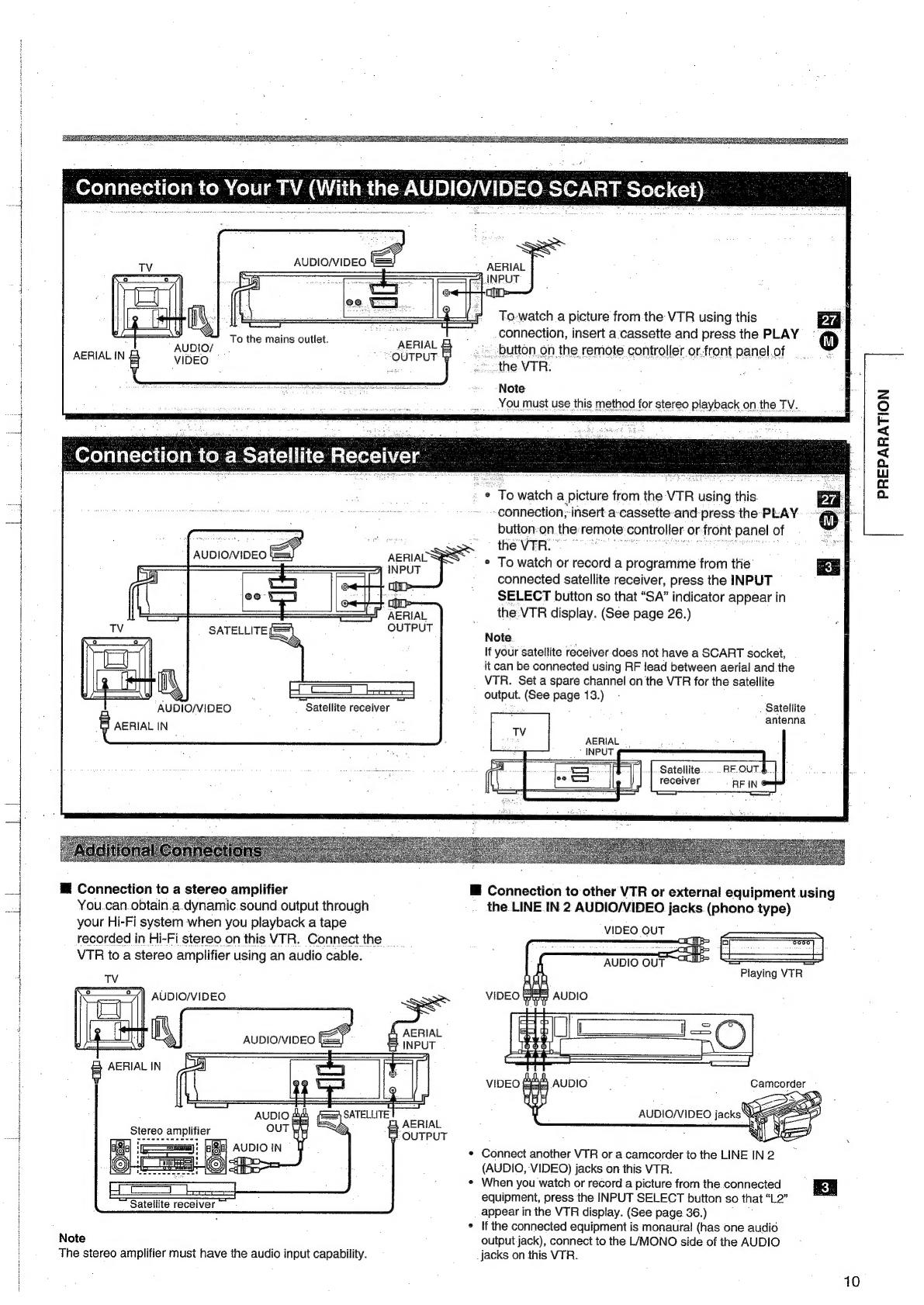
PREPARATION
Explains
what
you
need
to
do
before
operating
the
VTR.
PRECAUTIONS
uuu...
cescsesessceesseesteossdessecssausersesensecaesenseceendens
FEATURES
224.
s5
sist
acdsedecsatstteescatbocssvane
tere
stnuste
devstsvdeveeveacts
CONTENTS
siscesecsdiectetuertivacta
ra
ccitiiictieschs
vibes
ccesscateaaczioeces
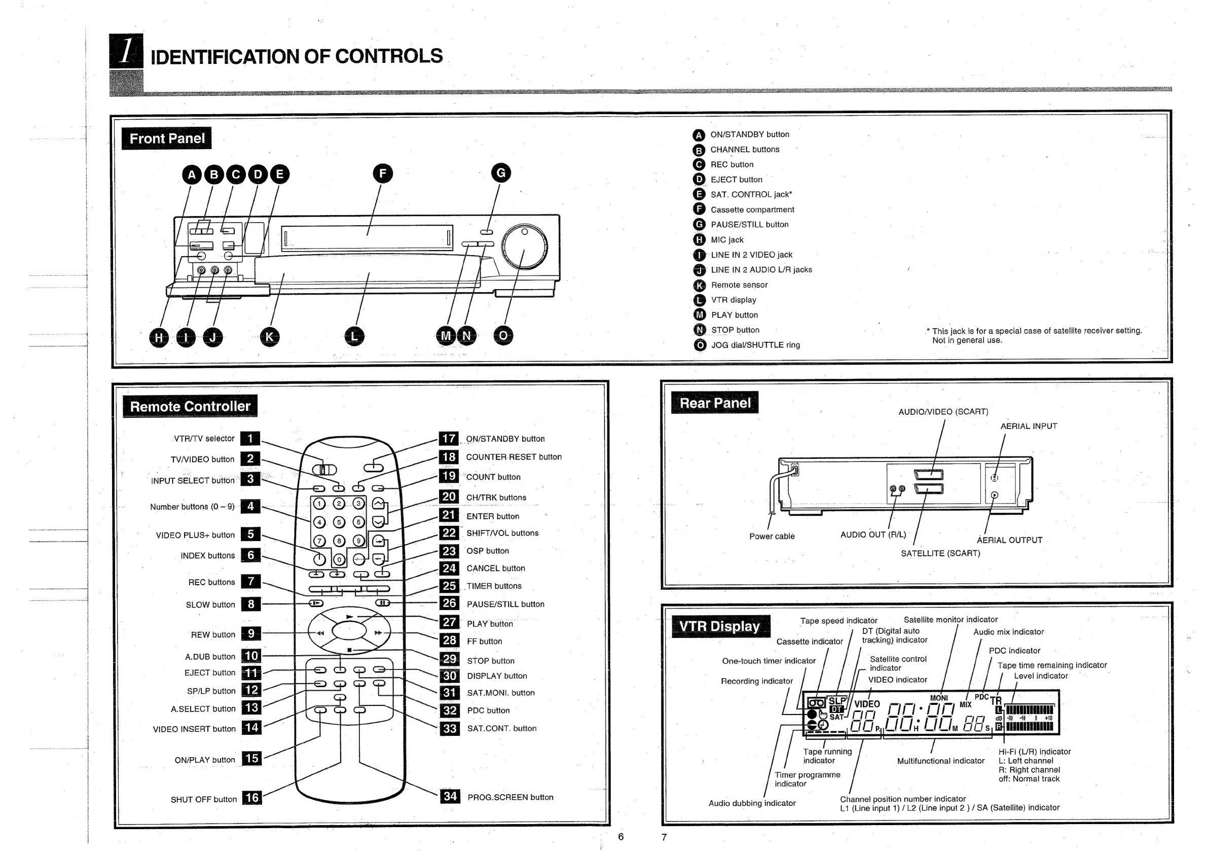
IDENTIFICATION
OF
CONTROLS
ou...
eececeeecseeeseeseeseeesees
;
e
Front
Panel
¢
Remote
Controller
¢
Rear
Panel
¢
VTR
Display
INTRODUCTION
|
PLAYBACK
Explains
various
functions
concerning
playback.
RECORDING
Explains
recording
functions.
ADDITIONAL
INFORMATION
HOW
TO
USE
THE
REMOTE
CONTROLLER
©.ueccetceees
28
2
CONNECTIONS
isscsccsesiceseosaetaxerssvodanpelagtacattivuntd
ieccsdeviescsenditeersee9
°
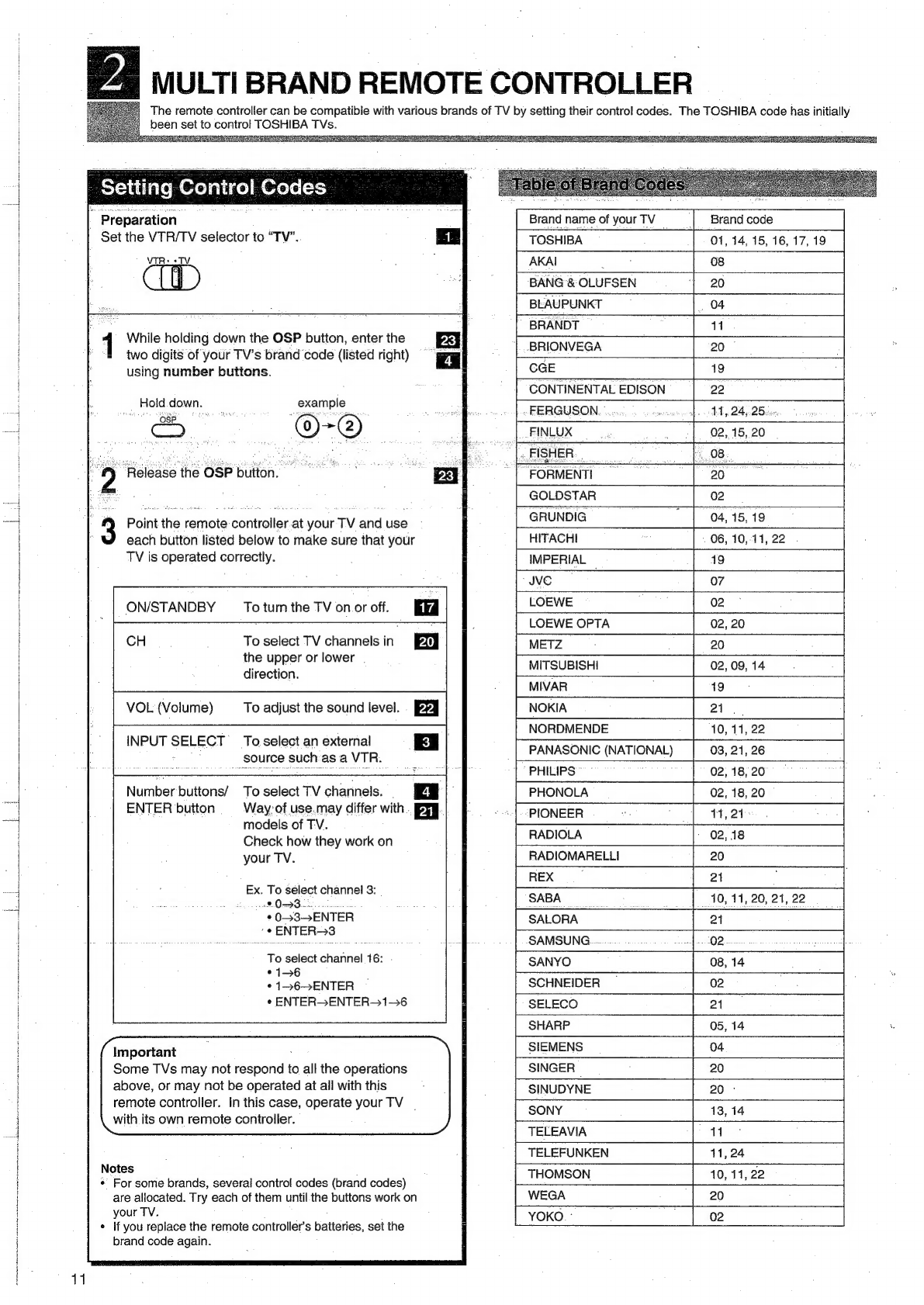
MULTI
BRAND
REMOTE
CONTROLLER
........ceececceeeeeseeetesteeees
14
=
INITIAL
SETTINGS
USING
ON-SCREEN
DISPLAY
.........
eee
12
io
*
Auto
Set-up
=
*
Setting
the
Clock
a
STORING
STATIONS
ON
THE
VTR
wo.secsseseseeetetseeseessneenenees
13
a
ALL-IN-ONE
OPERATION
.....cccccscscsccssseseseeneeeeneaeeeseensneseateeeetenee
15
VIDEO
CASSETTE
USE
oo...
ccceseeeseessseetsssesesestesesneasseeaseeeeeeneees
15
¥
ON
SCREEN
DISPLAY
....escscstesssesescseseesessessersseeatsearereaeenerasenssees
16
re)
PLAYBACK
pncroc
aureus
tice
seie
meth
Ase
lath
bs
NTSC-RECORDED
TAPE
PLAYBACK
......cscsccesseseseeseeeetesesseesees
18
>
VARIABLE
SPEED
PLAYBACK
.......ccesscscsssssssessessessseesteesneeeaees
19
=
16:9
(WIDE
SCREEN)
COMPATIBILITY
/
AUDIO
DUBBING
VIDEO
INSERT
EDITING
/
TAPE
COPYING
uuu...
ccceeeeseseeee
RECORDING
ADDITIONAL
INFORMATION
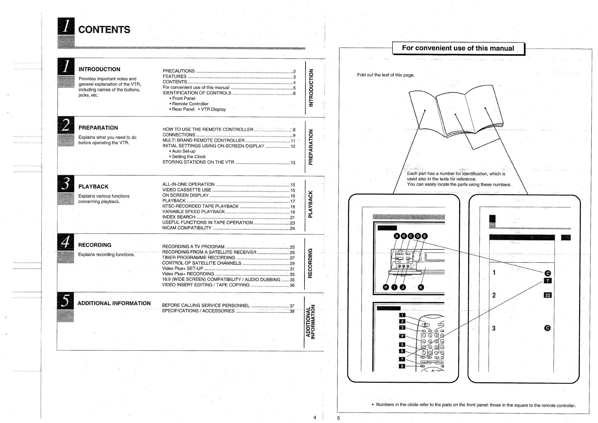
For
convenient
use
of
this
manual
Fold
out
the
leaf
of
this
page.
Each
part
has
a
number
for
identification,
which
is
used
also
in
the
texts
for
reference.
You
can
easily
locate
the
parts
using
these
numbers.
ERNEST
RE
SAN MMT TIS
Ie
TEAR
ES
ARO
AN
EAS
at
<>
pa
2
“1109
QB
eos
Jf
OQ0°0
eb
od
a
~a
i
ass
Al
ii
;
BREE
Hess
¢
Numbers
in
the
circle
refer
to
the
parts
on
the
front
panel:
those
in
the
square
to
the
remote
controller.