Toshiba W-804 User manual

Video Cassette Recorder
W-808
W-804
OWNER’S MANUAL
This publication is printed
on recycled paper
70971856
PLAY
STOP
P OG.TV
POWE EJECT
PAUSE/STILL
EC
FF
EV

2
WARNING: TO REDUCE THE RISK OF FIRE OR ELECTRIC SHOCK, DO NOT EXPOSE
THIS APPLIANCE TO RAIN OR MOISTURE. DANGEROUS HIGH
VOLTAGES ARE PRESENT INSIDE THE ENCLOSURE. DO NOT OPEN
THE CABINET. REFER SERVICING TO QUALIFIED PERSONNEL ONLY.
CAUTION: TO PREVENT ELECTRIC SHOCK, MATCH WIDE BLADE OF PLUG TO
WIDE SLOT, FULLY INSERT.
Product Name: Video Cassette ecorder
Model Number: W-808/W-804
FCC Notice: “Declaration of Conformity”
This device complies with part 15 of the FCC ules. Operation is subject to the
following two conditions: (1) This device may not cause harmful interference, and (2)
this device must accept any interference received, including interference that may
cause undesired operation.
Contact: Toshiba America Consumer Products, Inc.
Address: 1420 Toshiba Drive, Lebanon, TN37087
Telephone: 615-449-2360
User Installer Caution: Changes or modification made to this equipment not expressly
approved by Toshiba Corporation or parties authorized by Toshiba Corporation could
void the user’s authority to operate the equipment.
Note to CATV system installer:
This reminder is provided to call the CATV system installer’s attention to Article 820-40 of the
NEC that provides guidelines for proper grounding and, in particular, specifies that the cable
ground shall be connected to the grounding system of the building, as close to the point of cable
entry as practical.
The lightning flash with arrowhead symbol,
within an equilateral triangle, is intended to
alert the user to the presence of uninsu-
lated “dangerous voltage” within the
product’s enclosure that may be of sufficient
magnitude to constitute a risk of electric
shock to persons.
The exclamation point within an equilateral
triangle is intended to alert the user to the
presence of important operating and
maintenance (servicing) instructions in the
literature accompanying the appliance.
SAFETY PRECAUTIONS

3
INTRODUCTION
IMPORTANT PRECAUTIONS
Save Original Packing Materials
The original shipping carton and packing materials will come in handy if you ever have to ship
your VC . For maximum protection, repack the set as it was originally packed at the factory.
Avoid Volatile Liquid
Do not use volatile liquids, such as an insect spray, near the unit.
Do not leave rubber or plastic products touching the unit for a long time. They will mar the
finish.
Moisture Condensation
Never operate this unit immediately after moving it from a cold location to a warm location.
When the VC is exposed to such a change in temperature, moisture may condense on the
cylinder inside, one of its most crucial internal parts. To prevent the VC from possible
damage, do not use the unit for at least 2 hours when there is an extreme or sudden change
in temperature.
Copyright
It is permissible to record television programs, film, video tapes and other material only in the
event that third party copyrights and other rights are not violated.
Cassettes marked with “S-VHS” and “VHS” can be used with this video
cassette recorder. However, S-VHS recordings are possible only with
cassettes marked “S-VHS”.
By using S-VHS ET it is possible to record and play back with S-VHS picture
quality on VHS cassettes with this VC .
As an ENE GY STA ® Partner, TOSHIBA has determined that this product or
product model meets the ENE GY STA ® guidelines for energy efficiency.
In the spaces provided below, record the Model and Serial No. located at the rear of your video
cassette recorder.
Model No. Serial No.
etain this information for future reference.

4
1. ead owner’s manual
After unpacking this product, read the owner’s manual carefully, and follow all
the operating and other instructions.
2. Power Sources
This product should be operated only from the type of power source indicated
on the marking label. If you are not sure of the type of power supply to your
home, consult your product dealer or local power company. For products
intended to operate from battery power, or other sources, refer to the operating
instructions.
3. Grounding or Polarization
This product may be equipped with a polarized alternating current line plug (a
plug having one blade wider than the other). This plug will fit into the power
outlet only one way. This is a safety feature. If you are unable to insert the plug
fully into the outlet, try reversing the plug. If the plug should still fail to fit, contact
your electrician to replace your obsolete outlet. Do not defeat the safety
purpose of the polarized plug.
4. Ventilation
Slots and openings in the cabinet are provided for ventilation and to ensure
reliable operation of the product and to protect it from overheating, and these
openings must not be blocked or covered. The openings should never be
blocked by placing the product on a bed, sofa, rug or other similar surface. This
product should not be placed in a built-in installation such as a bookcase or rack
unless proper ventilation is provided or the manufacturer’s instructions have
been adhered to.
5. Heat
The product should be situated away from heat sources such as radiators, heat
registers, stoves, or other products (including amplifiers) that produce heat.
IMPORTANT SAFETY
INSTRUCTIONS
CAUTION: PLEASE READ AND OBSERVE ALL WARNINGS AND INSTRUCTIONS
GIVEN IN THIS OWNER’S MANUAL AND THOSE MARKED ON THE UNIT.
RETAIN THIS BOOKLET FOR FUTURE REFERENCE.
This set has been designed and manufactured to assure personal safety. Improper use can
result in electric shock or fire hazard. The safeguards incorporated in this unit will protect
you if you observe the following procedures for installation, use and servicing. This unit is
fully transistorized and does not contain any parts that can be repaired by the user.
DO NOT REMOVE THE CABINET COVER, OR YOU MAY BE EXPOSED TO
DANGEROUS VOLTAGE. REFER SERVICING TO QUALIFIED SERVICE PERSONNEL
ONLY.

5
INTRODUCTION
6. Water and Moisture
Do not use this product near water - for example, near a bath tub, wash bowl,
kitchen sink, or laundry tub; in a wet basement; or near a swimming pool and
the like.
7. Cleaning
Unplug this product from the wall outlet before cleaning. Do not use liquid
cleaners or aerosol cleaners. Use a damp cloth for cleaning.
8. Power-Cord Protection
Power-supply cords should be routed so that they are not likely to be walked
on or pinched by items placed upon or against them, paying particular attention
to cords at plugs, convenience receptacles, and the point where they exit from
the product.
9. Overloading
Do not overload wall outlets; extension cords, or integral convenience receptacles
as this can result in a risk of fire or electric shock.
ANTENNA
DISCHA GE UNIT
(NEC SECTION 810-20)
EXAMPLE OF ANTENNA GROUNDING AS PER
NATIONAL ELECTRICAL CODE
G OUND
CLAMP
ANTENNA
LEAD IN
WI E
ELECT IC
SE VICE
EQUIPMENT G OUNDING CONDUCTO S
(NEC SECTION 810-21)
G OUND CLAMPS
POWE SE VICE G OUNDING
ELECT ODE SYSTEM
(NEC A T 250, PA T H)
NEC – NATIONAL ELECT ICAL CODE
S2898A
10. Outdoor Antenna Grounding
If an outside antenna or cable system is connected to the product, be sure the antenna or cable system
is grounded so as to provide some protection against voltage surges and built-up static charges. Article
810 of the National Electrical Code, ANSI/NFPA 70, provides information with regard to proper
grounding of the mast and supporting structure, grounding of the lead-in wire to an antenna discharge
unit, size of grounding conductors, location of antenna-discharge unit, connection to grounding
electrodes, and requirements for the grounding electrode.
11. Power Lines
An outside antenna system should not be located in the vicinity of overhead power lines or other electric
light or power circuits, or where it can fall into such power lines or circuits. When installing an outside
antenna system, extreme care should be taken to keep from touching such power lines or circuits as
contact with them might be fatal.

6
16. Damage equiring Service
Unplug this product from the wall outlet and refer servicing to qualified service personnel under the
following conditions:
a) When the power-supply cord or plug is damaged.
b) If liquid has been spilled, or objects have fallen into the product.
c) If the product has been exposed to rain or water.
d) If the product does not operate normally by following the operating instructions. Adjust only those
controls that are covered by the operating instructions as an improper adjustment of other controls
may result in damage and will often require extensive work by a qualified technician to restore the
product to its normal operation.
e) If the product has been dropped or damaged in any way.
f) When the product exhibits a distinct change in performance - this indicates a need for service.
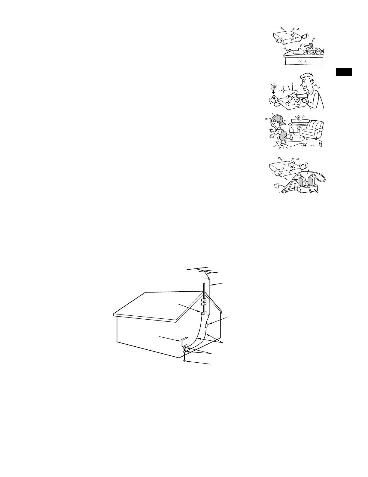
12. Lightning
For added protection for this product during storm, or when it is left unattended
and unused for long periods of time, unplug it from the wall outlet and
disconnect the antenna or cable system. This will prevent damage to the
product due to lightning and power-line surges.
13. Object and Liquid Entry
Never push objects of any kind into this product through openings as they may
touch dangerous voltage points or short-out parts that could result in a fire or
electric shock. Never spill liquid of any kind on the product.
15. Accessories
Do not place this product on an unstable cart, stand, tripod, bracket, or table.
The product may fall, causing serious injury to a child or adult, and serious
damage to the product. Use only with a cart, stand, tripod, bracket, or table
recommended by the manufacturer, or sold with the product. Any mounting of
the product should follow the manufacturer’s instructions, and should use a
mounting accessory recommended by the manufacturer.
A product and cart combination should be moved with care. Quick stops,
excessive force, and uneven surfaces may cause the product and cart
combination to overturn.
14. Attachments
Do not use attachments not recommended by the product manufacturer as they may cause hazards.
17. Servicing
Do not attempt to service this product yourself as opening or removing covers
may expose you to dangerous voltage or other hazards. efer all servicing to
qualified service personnel.
18. eplacement Parts
When replacement parts are required, be sure the service technician has used replacement parts
specified by the manufacturer or have the same characteristics as the original part. Unauthorized
substitutions may result in fire, electric shock, or other hazards.
19. Safety Check
Upon completion of any service or repairs to this product, ask the service
technician to perform safety checks to determine that the product is in proper
operating condition.
S3125A
IMPORTANT SAFETY
INSTRUCTIONS

7
INTRODUCTION
INTRODUCTION
Provides important notes and general
explanation of the VC , including names of the
buttons, jacks, etc.
SAFETY PRECAUTIONS .................... 2
IMPORTANT PRECAUTIONS.............. 3
IMPORTANT SAFETY
INSTRUCTIONS ................................... 4
Contents .............................................. 7
Identification of Controls ................... 8
• Front Panel
• emote Control
• VC Display
• ear Panel
PREPARATION
Explains what you need to do before operating
the VC .
How to Use the Remote Control ...... 10
Connections ...................................... 11
Auto Set Up ....................................... 14
Initial Settings Using On-screen
Display ............................................... 15
• Setting the Language
• Optional settings on the SET UP
screen 1 and 2
• Setting the Clock
Storing Channels on theVCR .......... 18
Video Cassette Use .......................... 20
PLAYBACK
Explains variable functions concerning
playback.
Playback ............................................ 21
Variable Speed Playback.................. 23
• Picture Search
• Still Picture
• Slow-motion Picture
• Frame Advance
• Double Speed Playback
• Jog Dial Operation
• Shuttle Dial Operation
Useful Functions inTape
Operation........................................... 25
• Counter Function
• Tape emaining Time
• Index Search Function
RECORDING
Explains recording functions.
Recording aTV Program .................. 27
• Watching a TV program while
recording another
• ecording off time setting
S-VHS (SuperVHS) and S-VHS ET
Recording .......................................... 28
• To ecord in S-VHS Mode
• To ecord in S-VHS ET Mode
Timer Program Recording ............... 30
VCR Plus+ C3®system Set-up ......... 33
VCR Plus+ C3®system Recording .. 35
Cable Box Set-up .............................. 37
DSS®Satellite Receiver Set-up........ 41
MTS Broadcast Compatibility.......... 44
Simulcast Recording ........................ 45
ADDITIONAL INFORMATION
Multi Brand Remote Control ............ 46
Before Calling Service Personnel ... 48
Specifications ................................... 50
Accessories....................................... 50
LIMITED WARRANTY ........................ 51
Contents

8
Front Panel
Remote Control
* These buttons are used to control the
cursor on the screen.
INTRODUCTION
Identification of Controls
See the page in for details.
This manual shows the names of buttons in italics.
To operate this VC .
To operate your TV.
PLAY
STOP
CHANNEL
POWE c EJECT
EV
(FWD
)
PAUSE/STILL
EC
VIDEO L-MONO-AUDIO- S-VIDEO
LINE IN 2
15
Cassette compartment
20
EC
27
CHANNEL
27
VC display
9
EJECT
20
POWE
emote sensor
LINE IN 2 S-VIDEO jack
10
PLAY
21
STOP
21
SHUTTLE
24
JOG
PAUSE/STILL
23
LINE IN 2 AUDIO
(L/MONO, ) jacks
LINE IN 2
VIDEO jack
24
CH/TRK
TV/VOL
VCR
PROG.
A.SELECT REMAIN
COUNTER COUNT
RESET
POWER CH DOWN CH UP
DNR
TV
213
546
879
0
100
DISPLAY
POWER
EJECT
CANCEL
PLAY/x2
ENTER
STOP
SLOW
VCR Plus+
INDEX
PAUSE/STILL
REW FF
SP/SLP
I.SELECT
TV/VCR
REC
CABLE BOX
TIMER
VCR
SP/SLP
FF *
TIMER
PLAY/x2 *
100
Number buttons
I.SELECT
A.SELECT
TV/VCR
PO ER (CABLE BOX)
CH DO N (CABLE BOX)
CH/TRK
PAUSE/STILL
CH UP (CABLE BOX)
VCR Plus+
21
RE *
15
PROG.
15
ENTER
26
INDEX
27
27
27
27
44
43
REC 27
35
CANCEL 32
43
SLO 23
14
TV 46
TV/VOL 46
19
PO ER 15
EJECT 20
27
DISPLAY 25
21
31
COUNT RESET 25
REMAIN COUNTER 25
43
21
23
DNR (For -808 only)
21
21
STOP *
Slide the lid down to open.

9
INTRODUCTION
Rear Panel
LINE IN 1 AUDIO (Rear), 2 (Front) jacks
If the connected equipment is monaural (has one audio output jack), connect the L (MONO) side, the same
sound is recorded on both L and on the Hi-Fi track.
Multifunctional indicator
EC ( ecording)
indicator
VC indicator
Tape speed indicator
(SP/SLP)
Cassette indicator Timer recording indicator
EMAIN indicator OFF indicator
Hi-Fi (L/ ) indicators
L: Left channel
: ight channel
OFF: Normal track
VCR Displa
POWE indicator
DT (Digital Auto Tracking) indicator
Channel indicator
Tape running direction/speed indicator
REMAIN
VCR
SLP
L
REC
TIMER
DT
CH HM
AM PM
OFF
S
R
POWER
To wall outlet
LINE IN 1 VIDEO jack
LINE IN 1 AUDIO jacks (L, )
CH selector (3/4)
LINE OUT AUDIO jacks (L, )
LINE OUT S-VIDEO jack
LINE IN 1 S-VIDEO jack
LINE OUT VIDEO jack
F IN (F OM ANT.) terminal
F OUT (TO TV) terminal
S-VHS ET indicator
S-VHS indicator

10
Setting up the Remote Control
1
Open the battery compartment on the
front of the emote Control by pressing on the
centre of the slide cover and pull off in one motion
in the direction of the arrow.
2
Install 2 batteries (“AAA” size) following
the polarity diagrams.
3
Close the battery compartment lid.
4
Point the remote control at the VC and press the buttons within the operating range.
Distance: within about 7 m from the front of the remote sensor
Angles: within about 30˚ in every direction
Notes on batteries
•The life of the batteries is about 1 year
depending on the conditions of use.
•If the remote control does not operate correctly,
replace all batteries with new ones.
•If the remote control is not to be used for a
long period of time, remove the batteries to
avoid possible damage from battery corrosion.
Caring for the remote control
•Do not expose the remote sensor of the VC
to a strong light source such as direct sunlight
or illumination (especially high-frequency
lighting) when using the remote control.
•Be careful not to spill water on the remote
control or to place it on anything wet, and avoid
sharp impacts.
How to Use the Remote Control
This section explains how to get ready for remote control operation.
Whenever you operate the VC , press VCR to set the remote control operating the VC .
PREPARATION
1
2

11
PREPARATION
Antenna/VCR/TV Connection
1
Disconnect the antenna cable from your TV and connect it to the RF IN terminal on the
VC .
2
Connect the RF OUT terminal to the TV.
AUDIO/VIDEO Connections
The AUDIO/VIDEO jacks are also available to connect your TV.
When connected our TV using the
AUDIO/VIDEO OUT jacks
To watch video pictures, set the video input mode on
your TV. For the video input mode, refer to the
manual of your TV.
Setting the VCR Output Channel
When the VC is connected in this way, the VC sends the output
signals to channel 3 or 4 on your TV. Set the output channel
selector (CH selector) of the VC to “3” or “4”, whichever is vacant
in your area.
VHF/UHF combination
antenna VHF antenna
only UHF antenna
only
Antenna splitter
(not supplied)
1
2
Connections
Before you use this VC , it is necessary to connect it to your TV. Several ways of connecting are
available depending on your use of TV or cable box. Select one which is applicable to your equipment.
PREPARATION
VHF UHF
VHF/UHF
OUT
(TO TV)
IN
(F OM ANT.)
LINE OUT VIDEO VIDEO IN
AUDIO INLINE OUT AUDIO

12
S-VIDEO Connection
The S-VIDEO jack is also available to connect to your TV.
This set-up will enable ou to:
– record an unscrambled channel.
– watch an unscrambled channel while recording it.
– record an unscrambled channel while watching
another (only when you connect a cable-
compatible TV).
You will need to:
• select TV channel 3 or 4 to receive video
signals. (See page 11.)
• to record a channel while watching another,
press
TV/VCR
on the remote control to turn off
the “VC ” indicator in the VC display and
select a desired channel on the TV (only when
you connect a cable-compatible TV).
This set-up will enable ou to:
– record an unscrambled channel.
– watch an unscrambled channel while recording it.
– record an unscrambled channel while watching
another (scrambled or unscrambled).
You will need to:
• set TV channel to the output channel of the
cable box.
• turn on the cable box and select cable channel 3
or 4 according to the output channel of the VC .
• to record a channel while watching another,
press
TV/VCR
on the remote control to turn off
the “VC ” indicator in the VC display and
select a desired cable channel on the cable box.
Connections (continued)
Incoming cable
Cable Box
Incoming cable
IN OUT
Cable Connection
Choose one of the below according to your usage of the cable box.
S-Video Cable
(supplied)
Audio/Video Cable
(supplied)
When connected our TV using the
S-VIDEO OUT jack
To watch video pictures, set the video input mode
on your TV. For the video input mode, refer to the
manual of your TV.

13
PREPARATION
This set-up will enable ou to:
– watch an unscrambled or scrambled channel
while recording it.
– record any channels through the cable box.
You will need to:
• set TV channel 3 or 4 to receive video signals.
(See page 11.)
• set VC channel to the output channel of the
cable box, and select a desired cable channel
on the cable box.
• while the VC is turned off or the “VC ”
indicator is not lit in the VC display, set TV
channel to the output channel of the cable box.
This set-up will enable ou to:
– watch an unscrambled or scrambled channel
while recording it.
– record an unscrambled channel while watching
another unscrambled channel (only when you
connect a cable-compatible TV).
• A/B switch “A”: record and watch an
unscrambled channel which
comes bypassing the cable box.
• A/B switch “B”: record and watch a scrambled
or unscrambled channel coming
through the cable box.
A/B switch
This set-up will enable ou to:
– watch or record a channel through the cable
box via the LINE IN 1 (AUDIO/VIDEO) jacks.
You will need to:
• press
I.SELECT
so that the VC display
shows “L1”.
A
B
A
B
A
B
Cable Box
Cable Box
OUTIN
Cable
Box

14
Auto Set Up
1
Connect the antenna cable to the VC (see page 11). Then connect the VC ’s power
plug to an AC outlet.
“Auto” flashes in the VC display as the VC automatically tunes in all active stations.
When Auto Set Up is completed successfully, the current time will be displayed.
• If the VC fails to set the clock, “– : – –” will be displayed. Set the clock manually. ( efer
to “Setting the clock” on page 17.)
PREPARATION
Auto Set Up
The Auto Set Up function automatically sets the tuner channels and clock when power is first connected
to the VC .
Preparation
• Turn on the TV, and select the video channel (3 or 4), or the video input mode if you made the Audio/Video
connection (page 11).
• Press
I.SELECT
so that the channel number will appear if “L1” or “L2” is displayed in the VC display.
• Press
VCR
to set the remote control operating the VCR.
Tuning in progress. Auto Set Up completed.
VC display
Notes
•If you press the
CANCEL
button, the Auto Set Up is cancelled.
•If Auto Set Up is not perform successfully, perform the clock and Tuner Channel procedures manually
(page 17 to 19).
•If, however, you want to add or delete channels, refer to “Adding or erasing channels” on page 19.
VC display
PM

15
PREPARATION
SET UP
PROGRAM
PRESET
PROG
H
120 016 801
OFFO
OFFO
UAT
OUA
M
EG RFA SPE
TAPE LE
SAP SET
SIMULCAST
GT
ANTE A
LA
nnn
n
n
n
OFFO
O
R
M
..E
n
n
GUAG
X
DS I
n
OFE
n
ED:
n
Optional settings on the SET UP screen 1
Other optional settings can be made. Press
ENTER
while “SET UP” is selected on the
MENU screen. The screen turns to the SET UP screen.
Press
STOP
repeatedly to go to screen 2 of SET UP page for more features.
To exit, press
PROG.
Setting the Language
1
Press
POWER
to turn on the VC .
2
Press
PROG.
.
The following screen appears on the TV.
3
Select the language using
PLAY/x2
(
CURSOR
) or
STOP
(
CURSOR
) , and press
PROG.
.
The screen turns to the MENU screen.
4
Press
PROG.
to return to the normal TV screen.
PREPARATION
Initial Settings Using On-screen isplay
Language selection must be set first when the VC is first plugged in, or after it encounters a power
failure. You can also easily make necessary settings using the on-screen displays.
Preparation
• Turn on the TV, and select the video channel (3 or 4), or the video input mode if you made the Audio/Video
connection (page 11).
• Press
VCR
to set the remote control operating the VCR.
PROG
SET UP
E
E
n
GLSIH
FRA
n
ÇA I
SPA
ñ
OL
S
ED:
n
PROGRAM
PRESET
PROG ENTER
ME
n
U
ED:
n
SET UP
PROGRAM
PRESET
(Continued)
A.SELECT REMAIN
COUNTER COUNT
RESET
POWER CH DOWN CH UP
DNR
213
546
879
0
100
PLAY/x2
ENTER
STOP
VCR Plus+
REW FF
PO ER
VCR
FF
ENTER
PROG.
RE
PLAY/x2,
STOP
To change the language, move down here and set to the desired one.
With “AUTO” set, a TV broadcast will appear via the TV tuner after
playback.
Move down here, and set to “AUTO” or “MANU”.
If you made the Audio/Video connection (page 11), set to “MANU”.
Page 25
Page 44
Page 45
With “ON” set, you can see the station ID and program title displayed on
TV.

16
Initial Settings Using On-Screen isplay (continued)
SET UP
PROGRAM
PRESET
PROG
OFFO
OFFO
IF
n
ETO
S
S-VHS REC
S-VHS ET
PLAY R
RF D
n
n
n
OFFO
n
OFFO
n
D
n
R
S
I
n
TUPD
n
R
F
ED:
n
O
R
M
..E
Optional settings on the SET UP screen 2
Press
PLAY/x2
repeatedly to go back to screen 1 of SET UP page.
To exit, press
PROG.
With “D
n
O
n
” selected (see page 21), move down here to obtain a
“FI
n
E” or “SOFT” playback picture. (For W-808 only)
Setting to ““FI
n
E” will give a normal picture with DN effect.
Setting to “SOFT” will give a softer picture.
Page 28
Page 29
With “O
n
” set, the reception from Antenna is improved with less
background noise. (For W-808 only)
With “O
n
” set, the reception from S-VIDEO is improved with less
background noise. (For W-808 only)

17
PREPARATION
8
Press
ENTER
to start the “AUTO” clock
set feature.
After a while, the VC automatically updates
the clock using the data broadcast by the
local TV stations.
The following screen will appear on TV
depending on the broadcast at your location.
9
Select the options using
FF
or
REW
.
Change the data using
PLAY/x2
or
STOP
.
1) Set “SUMME TIME (Daylight-
Saving Time)”.
IN, daylight-saving time begins on the first
Sunday in April. Because the clock
automatically changes from 2:00 AM to
3:00 AM (forward one hour), remember
that any part of a scheduled Timer
ecording that falls between these two
times will not be recorded.
OUT, daylight-saving time ends on the last
Sunday in October. The VC clock
automatically changes from 2:00 AM to
1:00 AM (back one hour). Therefore, it can
affect your recording length if one is set
for this time.
2) Set “Time Zone”.
If you select “AUTO” for your time zone,
the VC sets the clock using the first
Coordinated Universal Time information it
finds. If the time is not correct, select
another time zone or use the “MANU”
option.
3) Set “CH”.
If you don't know the clock data channel,
select “AUTO”. The VC will scan
automatically to tune the channel carrying
the clock data.
If AUTO CLOCK SET is unsuccessful, set the
time and date through the “MANU” clock set
menu selection.
10
Press
PROG.
.
Now the clock starts.
11
Press
PROG.
to exit.
PROG ENTER
AM
SU
MM
E
M
ERTI
57
9
:
10 00SA1’/
n
EZOH
C
TI
M
E
TEDAR
A
E
Y
TI
M
E
CL
O
CK SET
ED:
n
AUTO AUTO AUTO AUTO
EAS
I
n
TER
n
2
SET UP
PRESET
PROGRAM
PROG
CL
O
CK S
CH
M
E
MO
RY
CABLE B
GU I DE HCOX /DSS
ET
ENTER
ED:
n
SET UP
PRESET
PROGRAM
Setting the Clock
Example: To set the clock to 2:30 p.m. on
August 25 (summer time) 2000.
1
Press
PROG.
.
The MENU screen appears on the TV.
2
Select “P ESET” using
FF
or
REW
, and
press
ENTER
.
3
Press
ENTER
to select “CLOCK SET”.
4
Select “AUTO” or “MANU” using
PLAY/
x2
or
STOP
.
AUTO: The VC automatically sets or
adjusts the clock.
If you select “AUTO” mode, proceed to step 8.
MANU: You can set the clock manually.
If you select “MANU” mode, select “SUMME
TIME” using
FF
. Set to “IN” or “OUT” for the
summer (daylight saving) time using
PLAY/x2
or
STOP
. (For “IN” and “OUT” selections, see
the description in step 9.)
5
Move to the next using
FF
.
(To move back, press
REW
.)
6
Vary the digits to set the hour.
PLAY/x2
: To increase.
STOP
: To decrease.
7
epeat steps 5 and 6 to set the minutes,
month, day, and the year (by the last two
digits).
Proceed to step 10 to start the clock.
PROG
AM
SU
MM
E
M
ERTI
00
12 :
T
O
U1000SA1’/
TEDAA
R
YE
TI
M
E
CL
O
CK SET
ED:
n
SET UP
PRESET
PROGRAM
MA U
n

18
Incoming Antenna/Cable (CATV) Signals
The VC scans through all receivable TV and CATV channels and stores only the active
ones in your area into the memory. Once the storing is finished, you can select a desired
channel using
CH/T K
.
Preparation
• Turn on the TV, and select the video channel (3 or 4), or the video input mode if you made the Audio/Video
connection (page 11).
• Press
I.SELECT
so that the channel number will appear if “L1” or “L2” is displayed in the VC display.
Incoming Antenna/Cable (CATV) Signals
1
Press
PROG.
to display the MENU screen.
2
Select “P ESET” using
FF
or
REW
,
and press
ENTER
.
3
Select “CH MEMO Y” using
PLAY/
x2
or
STOP
, and press
ENTER
.
4
Set “TV/CATV“ to “TV” or “CATV” using
FF
or
REW
.
TV: To store channels received via the antenna.
CATV: To store channels received via the incoming cable.
5
Select “AUTO SCAN” using
PLAY/x2
or
STOP
, and press
FF
to set to
“ON”.
The VC starts scanning and the
channels are stored in the VC in
ascending order. When the scanning is
finished, the screen automatically
returns.
6
Press
PROG.
to exit.
PREPARATION
Storing Channels on the VCR
This section is required if you receive only normal TV or unscrambled cable channels, or use a cable box
between your TV and the VC .
PROG ENTER
ED:
n
SET UP
PRESET
PROGRAM
CL
O
CK S
CH
M
E
MO
RY
CABLE B
GU I DE HCOX /DSS
ET
PROG
TV TVAC
n
OFFOCH
CH
TV/C TAV
AUTO SCA
n
ADD CH
ERAS C
EH
ED:
n
––
––
SET UP
PRESET
PROGRAM
PROG
n
OCH2
TV
AUTO SCA
n
ED:
n
SET UP
PRESET
PROGRAM
A.SELECT REMAIN
COUNTER COUNT
RESET
POWER CH DOWN CH UP
DNR
213
546
879
0
100
PLAY/x2
ENTER
STOP
VCR Plus+
REW FF
1, 6
100
Number
buttons
I.SELEC
T
FF
ENTER
RE
PLAY/x2,
STOP

19
PREPARATION
To add channels
To erase channels
Adding or erasing channels
Adding channels
If a desired channel cannot be scanned
automatically because of a weak signal, it can be
added to the memory.
Erasing channels
You can erase a stored channel from the memory
if it is unnecessary.
1)Follow steps 1 to 3 of “Incoming Antenna/CATV
Signals”.
2)Select “ADD CH” or “E ASE CH” using
PLAY/X2
or
STOP
.
PROG
TV TVAC
n
O
n
O
n
O
FFO
OSETCH
PUSH ~90EYSK
T
––
––
TV/C TAV
AUTO SCA
n
ADD CH
ERAS C
EH
ED:
n
SET UP
PRESET
PROGRAM
PROG
TV TVAC
n
O
n
O
n
O
FFO
OSETCH
PUSH ~90EYSK
T
––
––
TV/C TAV
AUTO SCA
n
ADD CH
ERAS C
EH
ED:
n
SET UP
PRESET
PROGRAM
3)Enter a channel number of 1 to 125 using
number buttons
.
For more than 100 number, first press
100
.
For CATV channels, refer to the chart below.
(For other orders, check with your cable
company.)
4) epeat steps 2) and 3) to add or erase
channels as necessary.
5)Press
PROG.
to exit.
Selecting stored channels
Once the active channels have been stored, you
can select the channels in two ways below.
Number buttons
To enter digits of the channel number.
• For one-digit number, enter 0 before.
• For more than 100 number, first press
100
.
• Each
number button
needs to be pressed
within 2 seconds.
CH/TRK
To shift up or down the stored channel numbers.
Channel reference chart
Number on the VC
Corresponding channel number TV
CATV STD (H C/I C)
123456789
–23456789
1(A-8)
234
5(A-7) 6(A-6)
7
89
10 11 12 13 14 15 16 17 18 19 20 21 22 23 24 25 26 27 28 29 30
10 11 12 13 14 15 16 17 18 19 20 21 22 23 24 25 26 27 28 29 30
10 11 12 13 A B C D E F G H I J K L M N O P Q
31 32 33 34 35 36 37 38 39 40 41 42 43 44 45 46 47 48 49 50 51
31 32 33 34 35 36 37 38 39 40 41 42 43 44 45 46 47 48 49 50 51
STUVWAABBCCDDEEFFGGHHIIJJKKLLMMNNOO
52 53 54 55 56 57 58 59 60 61 62 63 64 65 66 67 68 69 70 71 …
52 53 54 55 56 57 58 59 60 61 62 63 64 65 66 67 68 69 – – …
PP QQ SS TT UU VV WW XX YY ZZ AAA BBB 65 66 67 68 69 70 71 …
93 94 95 96 97 98 99 100 101 102 103 …121 122 123 124 125
–––––––––––
…–––––
93 94 A-5 A-4 A-3 A-2 A-1 100 101 102 103 …121 122 123 124 125
CATV signals
• STD (standard) cable TV signals
• H C (Harmonic elated Carriers) cable TV signals
• I C (Incremental elated Carriers) cable TV signals
I C is also called ICC (Incremental Coherent Carriers)

20
Video Cassette Use
Loading a cassette
Push the cassette into the cassette compartment with the window side facing up and the
label side towards the front. The VC is automatically turned on. The indicator will
appear in the VC display.
Ejecting a cassette
Press
EJECT
. The cassette is ejected from the cassette compartment.
Warning
Do not insert your hands or any foreign objects into the compartment. This may result
in injury or damage. Take special care with children to avoid accidents.
Precautions when using video cassettes
Video cassettes have a safety tab to prevent accidental erasure. If the tab has already been removed,
recording cannot be performed.
To prevent accidental erasure
emove this safety tab with a screwdriver. To record again
Cover the tab hole with adhesive tape.
• Avoid exposing cassettes to direct sunlight. Keep them away from heaters.
Avoid extreme humidity, vibrations or shock, strong magnetic fields (near a motor, transformer or
magnet) and dusty place.
PREPARATION
Video Cassette Use
This manual suits for next models
1
Table of contents
Other Toshiba VCR System manuals

Toshiba
Toshiba M-64 User manual

Toshiba
Toshiba M-764 User manual

Toshiba
Toshiba W-727 User manual

Toshiba
Toshiba W-415 User manual

Toshiba
Toshiba M661 User manual

Toshiba
Toshiba W-704C User manual

Toshiba
Toshiba M-262 User manual

Toshiba
Toshiba M649 User manual

Toshiba
Toshiba M449 User manual

Toshiba
Toshiba M2390 User manual

Toshiba
Toshiba VE28 User manual

Toshiba
Toshiba W412C User manual

Toshiba
Toshiba W-627 User manual

Toshiba
Toshiba M-674 User manual

Toshiba
Toshiba W602 User manual

Toshiba
Toshiba KV-6200A User manual

Toshiba
Toshiba VIDEOplus+ V-855 User manual

Toshiba
Toshiba V-632EF User manual

Toshiba
Toshiba KV-7024A User manual

Toshiba
Toshiba W511 User manual