TOURTALK TT200 User manual

' ' ' '
' '' '
' '
' '
' '
' '
' '
' '
/
TWO-WAYTOUR GUIDE SYSTEM
USER MANUAL
V1020

' ' ' ' '
' '
'
' ' '
'
'
Thank
you
for
purchasing
this
TOURTALK
product.
Please
read
this
handbook and familiarise
yourself
with
the
equipment
prior
to
operation.
Should
you
require
more
information
please
contact
us.
The
equipment
has
been
tested
and
found
to
comply
with
the
limits
for
a
class
B
digital
device,
pursuant
to
part
15
of
the
FCC
Rules.
These
limits
are
designed
to
provide
reasonable
protection
against
harmful
interference
in
a
residential
installation.
This
equipment
generates,
uses
and
can
radiate
radio
frequency
energy
and
if
not
installed
and
used
in
accordance
with
the
instructions,
may
cause
harmful
interference
to
radio
communications.
However,
there
is
no
guarantee
that
interference
will
not
occur
in
a
particular
installation.
If
this
equipment
does
cause
harmful
interference
to
radio
or
television
reception,
which
can
be
determined
by
turning
the
equipment
off
and
on,
the
user
is
encouraged
to
try
to
correct
the
interference
by
one
or
more
of
the
following
measures:
·
Reorient
or
relocate
the
receiving
antenna.
·
Increase
the
separation
between
the
equipment
and
receiver.
·
Connect
the
equipment
into
an
outlet
on
a
circuit
different
from
that
to
which
the
receiver
is
connected.
·
Consult
the
dealer
or
an
experienced
radio/TV
technician
for
help.
The
Federal
Communications
Commission
Radio
Frequency
Interference
Statement
includes
the
following
paragraph:
This
device
complies
with
part
15
of
the
FCC
Rules.
Important
Note:
To
comply
with
the
FCC
RF
exposure
compliance
requirements,
no
change
to
the
antenna
or
the
device
is
permitted.
Any
change
to
the
antenna
or
the
device
could
result
in
the
device
exceeding
the
RF
exposure
requirements
and
void
the
users
authority
to
operate
the
device.
Operation
is
subject
to
the
following
two
conditions:
(1)
This
device
may
not
cause
harmful
interference,
and
(2)
this
device
must
accept
any
interference
received,
including
interference
that
may
cause
undesired
operation.
FCC Caution: To assure continued compliance, any changes or modifications not expressly approved
by the party responsible for compliance could void the users authority to operate this equipment.
(Example - use only shielded interface cables when connecting to computer or peripheral devices).
FCC Radiation Exposure Statement
This equipment complies with FCC RF radiation exposure limits set forth for an uncontrolled
environment. This equipment should be installed and operated with a minimum distance of 0.5
centimeters between the radiator and your body.
This transmitter must not be co-located or operating in conjunction with any other antenna or
transmitter.
The antennas used for this transmitter must be installed to provide a separation distance of at least
0.5 cm from all persons and must not be co-located or operating in conjunction with any other
antenna or transmitter.
Federal Communications Commission Interference Statement
Notice: The changes or modifications not expressly approved by the party responsible for
compliance could void the users authority to operate the equipment.
FCC Information

Table
of
Contents
System
components…….……………...……………………...……………….…………………………………………….………..…..4-5
Quick
start…………………………….…...……………………...……………….………………………………………………………..…..6-10
Interface……………………………………...……………………...……………….………………………………………………………..…11-12
General
operation…………………….…………..…………………..………………………………………..…………………............13-14
Advanced
operation….……………………………………………………………………………………………….…………….….......15-22
Troubleshooting..……..………………………………………..………………………………………………………………..……….....23-24
Specifications……………………………………………….…………..………………………………………………………………………25
This
p
E
T
W
E
o
P
p
roduct me
E
urope – E
U
T
his device
W
EEE Stat
e
E
lectrical a
n
o
f at the e
n
P
lease disp
o
or recyclin
g
ets the foll
o
U
Declarati
o
complies
w
e
ment
n
d electron
n
d of their li
o
se of this
e
g
center. Pl
e
o
wing stan
d
o
n of Confo
w
ith Directi
v
ic equipme
fespan sep
a
e
quipment
e
ase help t
o
d
ards:
rmity
v
e 2014/53
/
nt must be
a
rately fro
m
at your loc
a
o
protect o
u
/
EU issued
b
disposed
m
househol
d
a
l waste col
u
r environ
m
b
y the Com
d
waste.
lection
m
ent.
mission of
t
t
he Europe
a
a
n Commu
n
n
ity.
Safety and Electromagnetic Emissions Certificates
Standard Compliance
RoHs compliant
European Directive 2011/65/EU
Certificates
CE FCC NCC

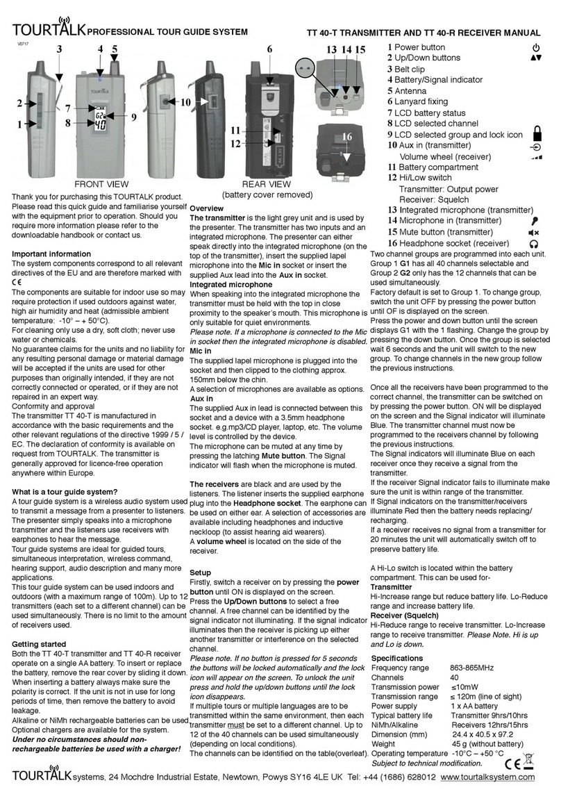
nSystem components
Tourtalk TT 200-T transmitter
The TT 200-T transmitter is used by a group leader or
assistant leader and is equipped with 3 communication
modes for different applications.
Tourtalk TT 200-ST
stationary
transmitter
The TT 200-ST
stationary
transmitter
is
designed
for
long
range
and
the
professional
conferencing
market
where
the
transmitter
is
to
be
mains
powered.
Tourtalk TT-C5S
charger
The
TT-C5S
is
a
five-slot
desktop
charger
with
channel
sync
function
for
the
TT
200-R
&
TT
200-T.
Tourtalk TT 200-R receiver
The TT 200-R receiver is used by group members to hear and
(when given permission) talk back to group leaders.
Tourtalk
TT-C5SC
charger
The
TT-C5SC
is
a
five-slot
portable
charger
(with
a
channel
sync
function
for
the
TT
200-R
&
TT
200-T)
and
protective
transport
case.
Tourtalk
TT-C25S
charger
The
TT-C25S
is
a
twenty-five-slot
portable
charger
(with
a
channel
sync
function
for
the
TT
200-R
&
TT
200-T)
and
protective
transport
case.
Tourtalk
TT-C50S
charger
The
TT-C50S
is
a
fifty-slot
desktop/rackmount
charger
with
channel
sync
function
for
the
TT
200-R
&
TT
200-T.
4

Tourtalk TT-SEH single ear headset
The TT-SEH is a single ear headset for use with TT 200-T
& TT 200-R.
Tourtalk TT-HQH headset
The TT-HQH is a dual on-ear headset for use with TT
200-T & TT 200-R. This headset can be used over ear
plugs if hearing protection is required.
Tourtalk TT-NPH noise reduction headset
The TT-NPH is a dual
over-ear
noise
reduction
headset
for use with TT 200-T &TT 200-R. This headset provides
hearing protection in noisy enviroments. Aversion
that
can be worn with ahardhat is also available.
Awide range of other accessories are available. Please
visit www.tourtalksystem.com for details.
Guiding,
Teaching
(default)
and
Discussion.
Both the TT 200-T transmitter and TT 200-R receiver operate on
two
AA
batteries.
To
insert
or
replace the batteries, remove the rear cover by sliding it down. Always insert batteries of the
same type and make sure the polarity is correct. If the unit is not in use for long periods of time
,
then
remove
the
batteries
to
avoid
leakage.
Alkaline or NiMh rechargeable batteries can be used. Under no circumstances should non-
rechargeable batteries be used with acharger!
The Tourtalk TT 200 is afull-duplex two-way communication system that allows group leaders
and group members to fully communicate with each other during atour. The system allows the
tour group to talk to and be heard by each other; making it more convenient for visitor tours with
question
and
answer
sessions
or
interviews,
meetings
on
the
shop
floor,
staff
training
and
many
other
applications.
There
are
three
communication
modes-
5

Quickstart
ModeGuiding
Thegroupleader(TT 200-T)
can
freely
talk
during
the
tour.
Any
one
(1)
of
group
members
is
able
to
talkbackorraiseaquestioninawayofFIFT(first‐in‐first‐talk)whenthegroupleaderpermits.
Power on a transmitter, connect a headset and change its communication mode
Pressboth(○
8
)andpower(○
9
)buttontoturnthetransmitteron.
DefaultmodeTEACHINGshowsup.Presstheorbutton(○
8
)toselectGUIDINGmode.
Pressthepowerbutton(○
9
)toconfirm(underline)theselectionandleavethesetting.
Thetransmitterwillthenbeturnedonautomatically.
Assignyourgroupchannel
Pressbothandbuttons(○
8
)simultaneouslytounlockthechannelwhentransmitteris
on.
Symbol disappearsandpressorbutton(○
8
)toselectanotherpreferredchannel.
Toconfirmnewlyselectedchannel,pressthepowerbutton(○
9
)orleavethetransmitter
idle
for
1
second
to
leave
the
setting.
Power
on
a
receiverandconnectan earphone,headphone orheadset
Now,pressandholdthepowerbutton(○
21
)for1secondtoturnthereceiveron.
Pressbothandbuttons(○
20
)simultaneouslytounlockthechannel.
Symbol disappearsandpressorbutton(○
20
)toselectsamechannelasthaton
transmitter.
Toconfirmnewlyselectedchannel,pressthepowerbutton(○
21
)orleavethereceiveridle
for1secondtoleavethesettingautomatically.
6

Gwillshowuponthescreentoindicatecorrectconnectionwiththetransmitter.Noteboth
transmitterandreceiverneedtobesetatsamechanneltohavecorrectcommunication
mode(G,TorD)shownonreceiver’sscreen.
Talkbackbyreceiver
Anyone(1)groupmember(receiver)isallowedtotalkback(FIFT)withapressofPTTbutton
(○
17
)ifthegroupleader(transmitter)tunesitsmaster/slaveswitch(○
10
)to“s”.
Poweroff
Toturntransmitter/receiveroff,pressandholdthepowerbutton(○
9
○
21
)tillOFFshowsupon
thescreen.
Mode
Teaching
In
addition
to
the
lecturer
(TT‐200T,
master),
either
the
assistant
(TT‐200T,
slave)
or
any
one
(1)
participant
(TT‐200R)
is
allowed
to
talk
in
the
room
in
a
way
of
FIFT
(first‐in‐first‐talk).
Power on a transmitter, connect a headset and change its communication mode
Pressandholdthepowerbutton(○
9
)for1secondtoturntransmitteron.DefaultmodeT
isshownontransmitter. See Mode Guiding notes to change transmitter communication
mode.
7

Tunemaster/slaveswitchontransmittercorrectly
Thelecturer(mastertransmitter)tunesitsmaster/slaveswitch(○
10
)to“m”whereas“s”is
tunedbytheassistant(slavetransmitter).Noteslavetransmittercanworkonlywhenmaster
transmitterexists.
Assignyourgroupchannel
Pressbothandbuttons(○
8
)simultaneouslytounlockthechannelwhentransmitteris
on.
Symbol disappearsandpressorbutton(○
8
)toselectanotherpreferredchannel.
Toconfirmnewlyselectedchannel,pressthepowerbutton(○
9
)orleavethetransmitter
idlefor1secondtoleavethesettingautomatically.
Poweron areceiverand connectan earphone,headphone orheadset
Now,pressandholdthepowerbutton(○
21
)for1secondtoturnthereceiveron.
Pressbothandbuttons(○
20
)simultaneouslytounlockthechannel.
Symbol disappearsandpressorbutton(○
20
)toselectsamechannelasthaton
transmitter.
Toconfirmnewlyselectedchannel,pressthepowerbutton(○
21
)orleavethereceiveridle
for1secondtoleavethesettingautomatically.
Twillshowuponthescreentoindicatecorrectconnectionwiththetransmitter.Noteboth
transmitterandreceiverneedtobesetatsamechanneltohavecorrectcommunication
mode(G,TorD)shownonreceiver’sscreen.
Talkbackbyreceiver
Anyone(1)participant(receiver)(FIFT)canpressPTTbutton(○
17
)totalkbackiftheassistant
(slavetransmitter)releaseshistalkright.
Poweroff
Toturntransmitter/receiveroff,pressandholdthepowerbutton(○
9
○
21
)tillOFFshowsupon
thescreen.
Makesureslave transmittercarriedbytheassistantis ○
i
muted or ○
ii
itsaudiocableisremoved
fromaux‐injack (○
2
),ifapplicable.
8

ModeDiscussing
Any2discussionmembers(TT‐200T)
are
allowed
to
talk
freely.
Other
listeners
(TT‐200R)
can
only
be
in
listen
mode
at
this
occasion.
Power on a transmitter, connect a headset and change its communication mode
Press
both
(○
8
)
and
power
(○
9
)
button
to
turn
transmitter
on.
Default
mode
T
EACHING
shows
up.
Press
the
or
button
(○
8
)
to
select
D
ISCUSSING
mode.
Press
the
power
button
(○
9
)
to
confirm
(underline)
the
selection
and
leave
the
setting.
Transmitter
will
then
be
turned
on
automatically.
Assign
your
group
channel
Press
both
and
buttons
(○
8
)
simultaneously
to
unlock
the
channel
when
transmitter
is
on.
Symbol
disappears
and
press
or
button
(○
8
)
to
select
another
preferred
channel.
To
confirm
newly
selected
channel,
press
the
power
button
(○
9
)
or
leave
the
transmitter
idle
for
1
second
to
leave
the
setting
automatically.
Poweron areceiverand connectan earphoneor headphone
Now,
press
and
hold
the
power
button
(○
21
)
for
1
second
to
turn
the
receiver
on.
Press
both
and
buttons
(○
20
)
simultaneously
to
unlock
the
channel.
Symbol
disappears
and
press
or
button
(○
20
)
to
select
same
channel
as
that
on
transmitter.
To
confirm
newly
selected
channel,
press
the
power
button
(○
21
)
or
leave
the
receiver
idle
for
1
second
to
leave
the
setting
automatically.
D
will
show
up
on
the
screen
to
indicate
correct
connection
with
the
transmitter.
Note
both
9

transmitterandreceiverneedtobesetatsamechanneltohavecorrectcommunication
mode(G,TorD)shownonreceiver’sscreen.
Poweroff
Toturntransmitter/receiveroff,pressandholdthepowerbutton(○
9○
21 )tillOFFshowsupon
thescreen.
Whenreceiversareatcommunicationmode“Discussing”,theydonothavethetalkrightviathe
talk/mutebutton(○
17 ).
10

Interface
Transmitter
TransmitterScreen
1. Whipantenna
2. Aux‐injack
3. Signal/Statusindicator
4. OLEDscreen(seebelow)
5. Talk/Mutebutton
6. Callbutton
7.Beltclip
8.Up/Downbutton
9.Powerbutton
10.Master/Slaveswitch
11.Headsetjack socket
12. Inbuiltmicrophone
Talksettings
Channelnumber
Channellock
Communicationmode
Batterystatus
○
1
○
2
○
3
○
4
○
5
○
6
○
7
○
8
○
9
○
10
○
11
○
12
The recommended 4-pin jack wiring is shown
below
Please note. The Inbuilt microphone is muted when a headset
is plugged into the jack socket
11

Receiver
Receiverscreen
13. Antenna
14. Volumecontrol
15. Signal/Statusindicator
16. OLEDscreen(seebelow)
17. PTT(pushtotalk)button
18. Alarm‐releasebutton
19. Beltclip
20. Up/Downbutton
21. Powerbutton
22. Earphone/Headphone/Headsetjack socket
23. Inbuiltmicrophone
Channelnumber
Channellock
Communicationmode
Batterystatus
○
13
○
14
○
15
○
16
○
17
○
18
○
19
○
20
○
21
○
22
○
23
The recommended 4-pin jack wiring is shown
below Please note. The Inbuilt microphone is muted when a headset
is plugged into the jack socket
12

Generaloperation
Poweron
Pressandholdthepowerbutton(○
9
○
21
)for1secondtoturn transmitter/receiveron.
Changecommunicationmodeontransmitter
Pressandholdboth(○
8
)andpower(○
9
)buttonssimultaneouslytoturntransmitteron.
DefaultmodeTEACHINGshowsup.Presstheorbutton(○
8
)tochangeyourpreferred
mode.
Pressthepowerbutton(○
9
)toconfirm(underline)theselectionandleavethesetting.
Transmitterwillthenbeturnedonautomatically.
Detectcommunicationmodeonreceiver
Receiverwillautomaticallydetectthesignalfromtransmitterwhenitisturnedon.
T,GorDwillthenshowuponreceiver’sscreenformodedifferentiationandindicatingcorrect
connectionwiththetransmitter.Notebothtransmitterandreceiverneedtobesetatsame
channel,thencommunicationmodewillshowupautomatically.
Tochangeyourmode,simplyturnreceiveroffandthenre‐turnitontoacquirenewsignalfrom
anothertransmitter.
Assignyourgroupchannel
Pressbothandbuttons(○
8
○
20
)simultaneouslytounlockthechannelwhentransmitteror
receiverison.
Symbol disappearsandpressorbutton(○
8
○
20
)toselectanotherpreferredchannel.
Toconfirmnewlyselectedchannel,pressthepowerbutton(○
9
○
21
)orleavethetransmitteror
receiveridlefor1secondtoleavethesettingautomatically.
Bothtransmitterandreceivercanworktogetheronlywhentheirchannelandcommunication
modearesame.
*Redlightwillshowupiflowbattery.
Whenthecommunicationbetweentransmitterandreceiveriscorrect,theirsignalindicators
(○
3
○
15
)willshowbelow.
‐
Transmitter:
Slow
flashing
blue
*
light
(
Steady
blue
light
shows
up
if
the
transmitter
acquires
thesignalfromonereceiver.)
‐
Receiver: Steady
blue
*
light
(Slowflashing
blue
light
shows
up
if
it
does
not
acquire
the
signalfromthetransmitter.)
13

Adjusttransmitter’sorreceiver’svolume
Transmitter
Pressorbutton(○
8)toadjusttheheadphonevolumeontransmitter.
Receiver
Tunethevolumecontrol(○
14 )onthesideofreceiverforadjustment.
Connectexternalaudio(Transmitter)
3.5mmaudioconnectionviaaux‐injack(○
2).
Poweroff
Pressandholdthepowerbutton(○
9○
21 )tillOFFshowsuponthescreentoturn
transmitter/receiveroff.
Total11volumelevelsareavailableanddefaultlevelissetat5.Whenlevel0isset,thedevicewill
bemuted.
Please note. Listening to high volumes for long periods may damage your hearing
.
Toreleasethetalkrightof2ndtransmitterwhenitiscommunication mode“Teaching(slave)”or
“Discussing”,makesureitis ○
imutedor○
ii theaudiocableisremovedfromaux‐injack(○
2),if
applicable.
14
!" #$%&&'()(*#+ ",&#-*& ./ 0'%#-1%2'0 3/'' 4%5%65%4$ *" 7809,/2 0'"%,(2/'22.&6/:*& page 21;<
1*(,='%09,/2='&2 >.((?' .&1%(.0%&00'"%,(2 1*(,='>.((?' ".@'0 %2 ('1'( AB
!“Audio priority (default: OFF)”can be pre-set uponpreferenceas advisedin theparagraphof
“Adjust defaultsettings” on page21.

DevelopbespokeID
Tourtalks proprietary software is available for developing bespoke ID numbers (max. of 4 digits)
on
the TT 200-T. Please contact us for details.
Unify
your
group
channel
automatically
Press
both
talk/mute
(○
5
)
and
power
buttons
(○
9
)
to
turn
transmitter
on.
Channel
number
flashes.
Press
or
button
(○
8
)
to
select
preferred
channel.
To
confirm
newly
selected
channel,
press
the
power
button
(○
9
)
or
leave
the
transmitter
idle
n
Advanced operation
Successful
channel
unification
Failed
channel unification
Last
channel
used
displayed
No
light Steady
blue
light Flashing
blue
light Flashing
blue
light
Flashing red light No light Steady green light Flashing red light
for 10 seconds
Symbol indication
15

for5secondsforauto‐confirmation.
Afterselectedchannelisconfirmed,signalindicator(○
3
)startstoflashquicklyandthe
talk/mutebutton(○
5
)lightsupingreen.Transmitterisreadytosendsignalofchannel
unification.
Now,turnreceiveronanditwillautomaticallybechannelunified.Newchannelandcorrect
communicationmode(G,TorD)willshowuponitsscreen.Indicationofsuccessfulorfailed
channelunificationisshownabove.
Turnreceiveroffandthenre‐turnitoniffailedchannelunificationhappens.
Toreleasethetransmitterfromchannelunification,simplyshortpressthetalk/mutebutton
(○
5
)again.
Pairandunifyyourgroupchannel
Pressbothcall(○
6
)andpower(○
9
)buttonstoturntransmitteronforgrouppairingandchannel
unification.
Channelnumberontopflashes.Presstheorbutton(○
8
)toselectpreferredchannel.
Toconfirmnewlyselectedchannel,pressthepowerbutton(○
9
)orleavethetransmitteridle
Communicationmode(G,TorD)shown onreceiver’sscreenvariesupontransmitterfromwhich
receiveracquiresthesignal.
Tocompletefollowingadvancedfunctions,includingroll‐call
,
calling/gatheringalarm or
ou
t
‐of‐rangealarm
,
priorpairing foralltransmitters/receiversinthegroupisamust.
Whenthetransmitterisatcommunicationmode“Teaching”,onlymaste
r
transmitter,
whosemaster/slaveswitch(
○
10
)issetat“m”,canexecutefollowingadvancedfunctions,
includingroll‐calland
c
allingalarm.
Successful pairing
Failed pairing
Selected channel
Paired quantity
16

for5secondsforauto‐confirmation.
Channelnumberstopsflashing.Signalindicator(○
3
)startstoflashquicklywhichmeansthe
transmitterisreadyforpairing.
Now,turnreceiveron.Itwillbepairedandchannelunified.Indicationofsuccessfulorfailed
pairingisshownabove.
Turnreceiveroffandthenre‐turnitoniffailedpairinghappens.
Pairingquantityshownontransmitterwillgraduallyincreaseuntilpairingiscompleted.
Toreleasethetransmitterfromgrouppairing,simplyshortpressthecallbutton(○
6
)againto
haveitatstandbyscreenorpressthepowerbutton(○
9
)toturnitoffdirectly.
Sendpairingdatatoanothertransmitter
Keep1
st
transmitteronafterithaspairedallgroupmembers(receivers).Notethistransmitter
cannotreleaseitselffrompairingmodeatthisstep.
Now,pressbothcall(○
6
)andpower(○
9
)buttonstoturn2
nd
transmitteroninordertoobtain
pairingdatafrom1
st
transmitter.Notesamecommunicationmodeandchannelneedtobeset
onbothtransmitters(ifthecommunicationmodeis“Teaching”,themaster/slaveswitch(
○
10
)on
bothtransmittersneedstobetunedat“m”).
Turn2
nd
transmitteroffandthenre‐turnitoniffailed pairing data occurs.
Toreleasetransmittersfromtransmission/acquirementofpairingdata,simplyshortpressthe
callbutton(○
6
)againtohaveitatstandbyscreenorpressthepowerbutton(○
9
)toturnitoff
directly.
Successful pairing
Failed pairing
17

Roll‐call
Short
press
the
call
button
(○
6
)
when
transmitter
is
on.
Roll‐call
symbol
( )
shows
up
and
signal
indicator
(○
3
)
starts
to
flash
quickly
which
means
the
transmitter
is
sending
the
signal
of
roll‐call.
If
receiver
acquires
roll‐call
signal
from
the
transmitter,
its
signal
indicator
(○
15
)
will
flash
quickly
for
10
seconds
and
then
in
steady
blue
light
again.
The
number
shown
on
transmitter
will
gradually
increase
until
roll‐call
is
completed.
To
release
the
transmitter
from
roll‐call,
simply
short
press
the
call
button
(○
6
)
again.
Actual group size Expected group size
18

Callingalarm
Press
and
hold
the
call
button
(○
6
)
on
transmitter
for
3
seconds
when
transmitter
is
on.
Calling
symbol
( )
shows
up
and
signal
indicator
(○
3
)
starts
to
flash
quickly
which
means
the
transmitter
is
sending
the
signal
of
calling
alarm.
Receivers,
which
receive
the
calling
alarm
from
transmitter,
will
start
to
vibrate
and
beep.
Also,
symbol
of
gathering
alarm
( )
shows
up
on
the
screen
and
its
PTT
button
(○
17
)
starts
to
flash
quickly
in
red
light.
To
release
receivers
from
being
alarmed,
simply
press
the
alarm‐release
button
(○
18
).
To
release
the
transmitter
from
calling
alarm,
simply
short
press
the
call
button
(○
6
)
again.
Receivers
will
automatically
be
turned
off
if
the
alarm
keeps
on
for
20
minutes.
19

Out‐of‐rangealarm
Receiverswillautomaticallystarttovibrateandbeepiftheyareoutoftransmitter’srangefor3
minutes.
Out‐of‐rangesymbol( )showsupandPTTbutton(○
17
)startstoflashquicklyinred
light.
Thealarmcanonlybereleasedwhenreceiversarewithintheoperationrangeofthe
transmitteragainorthealarm‐releasebutton(○
18
)onreceiversisshortpressed.
Receiverswillautomaticallybeturnedoffifthealarmkeepsonfor20minutes.
20
Out-of-range alarm can be deac1vated upon preference as advised in the paragraph of “Adjust default
settings”on page 21.
This manual suits for next models
9
Table of contents
Other TOURTALK Two-way Radio manuals
