Tower Light VT1 9mt 4x1.000W User manual

TL006-09-00-00
25-08-2005
VERSIÓN SH
MANUAL DEL USUARIO
Mod. VT1 9mt 4x1.000W HALOGENURO METÁLICO
OWNER’S MANUAL
Mod. VT1 9mt 4x1.000W METAL HALIDE

VT1 9 m 4x1.000W HALOGENURO METÁLICO
2TL006-09-00-00
28-08-2005
VERSIÓN SH
ÍNDICE - INDEX
1. ARTÍCULO 113 - ARTICLE 113.............................................................................................. 3
2. INFORMACIÓN GENERAL - GENERAL INFORMATION ................................................. 4
2.1 DOCUMENTACIÓN DE LA TORRE DE ILUMINACIÓN - EQUIPMENT DOCUMENTATION OF
THE LIGHTING TOWER............................................................................................................................................ 4
3. DESCRIPCIÓN GENERAL DE LA MÁQUINA - GENERAL DESCRIPTION OF THE
MACHINE .................................................................................................................................... 5
3.1 PERÍODO DE INACTIVIDAD - PERIOD OF INACTIVITY ..................................................................... 6
3.2 MANTENIMIENTO Y LIMPIEZA - SERVICE AND CLEANING............................................................. 6
4. CARACTERÍSTICAS TÉCNICAS - TECHNICAL SPECIFICATION................................. 7
4.1 GENERADOR - GENERATOR................................................................................................................... 7
4.2 MOTOR - ENGINE ....................................................................................................................................... 7
4.3 TORRE DE ILUMINACIÓN - LIGHTING TOWER................................................................................... 8
4.4 FOCO - FLOODLIGHT................................................................................................................................. 9
5. DESCRIPCIÓN DE LOS CONTROLES - CONTROLS DESCRIPTIONS...................... 10
6. DESCRIPCIÓN DE LOS CONTROLES LATERALES - SIDE CONTROLS
DESCRIPTIONS....................................................................................................................... 12
7. INSTRUCCIONES DE USO - OPERATING INSTRUCTIONS......................................... 13
7.1 CONECTAR LA BATERÍA - CONNECTING TO THE BATTERY ....................................................... 13
7.2 CONEXIÓN A TIERRA - EARTH CONNECTION ................................................................................. 13
7.3 ENCENDER EL MOTOR - ENGINE STARTING................................................................................... 13
7.4 RODAJE - RUNNING IN............................................................................................................................ 14
7.5 USO DE LA MÁQUINA - USE OF MACHINE ........................................................................................ 14
7.6 PARAR EL MOTOR - STOPPING THE ENGINE.................................................................................. 15
7.7 ALARMAS DEL GENERADOR - GENERATOR ALARMS .................................................................. 15
8. INSTRUCCIONES PARA EL USO DE LA TORRE DE ILUMINACIÓN -
INSTRUCTION FOR USE OF THE LIGHTING TOWER................................................... 16
8.1 DIAGRAMA DE LA COBERTURA DE ILUMINACIÓN - LIGHTING FOOT PRINT DIAGRAM ...... 16
9. BAJAR EL MÁSTIL EN CASO DE EMERGENCIA - LOWERING HANDLE BAR
BRACKET IN CASE OF EMERGENCY............................................................................... 17
10. CAUSAS DE UN BAJO RENDIMIENTO DEL MOTOR - CAUSES OF ENGINE POOR
PERFORMANCE...................................................................................................................... 18
11. GUÍA PARA LA RESOLUCIÓN DE PROBLEMAS - TROUBLESHOOTING GUIDE.24
12. LISTA DE RECAMBIOS - PARTS LIST .............................................................................. 26
12.1 LISTA DE RECAMBIOS DEL FRONTAL - SPARE PARTS LIST FOR THE MACHINE ................. 26
12.2 LISTA DE RECAMBIOS DE LA PARTE HIDRÁULICA - SPARE PARTS LIST HYDRAULIC
PARTS 29
12.3 LISTA DE RECAMBIOS DEL BASTIDOR - SPARE PARTS LIST FOR FRAME............................. 31
12.4 LISTA DE RECAMBIOS DE LA CARPINTERÍA METÁLICA - SPARE PARTS LIST FOR
CARPENTRY............................................................................................................................................................. 34
12.5 LISTA DE RECAMBIOS DE LA CONEXIÓN MONOFÁSICA AUXILIAR Y DE LAS PLACAS -
SPARE PARTS LIST FOR SINGLE PHASE AXILIARY AND PLATES............................................................ 36
12.6 LISTA DE RECAMBIOS DEL MÁSTIL TELESCÓPICO - SPARE PARTS LIST FOR
TELESCOPIC MAST................................................................................................................................................ 38
12.7 LISTA DE RECAMBIOS DEL ALTERNADOR - SPARE PARTS LIST FOR ALTERNATOR ......... 41
12.8 LISTA DE RECAMBIOS DEL REMOLQUE DE RUEDAS LATERALES CON LANZA DE
REMOLCADO - SPARE PARTS LIST FOR WHEELS SIDE TRAILER WITH TOWING BAR ..................... 43
13. DIAGRAMA ELÉCTRICO (PRIMERA PARTE) - WIRING DIAGRAM FIRST PART... 44
14. DIAGRAMA ELÉCTRICO (SEGUNDA PARTE) - WIRING DIAGRAM SECOND PART45
15. GARANZIA - GUARANTEE ................................................................................................... 46

VT1 9 m 4x1.000W HALOGENURO METÁLICO
3TL006-09-00-00
28-08-2005
VERSIÓN SH
1. ARTÍCULO 113 - ARTICLE 113
Antes de instalar la máquina y antes de
llevar a cabo cualquier operación, lea
atentamente este manual de instrucciones
y uso, y en caso de que alguna parte de
este manual no quedara totalmente clara o
no fuera totalmente comprensible,
póngase directamente la TOWER LIGHT
S.r.l. llamando al número:
Before install the machine and however
before every operation, read carefully
following manual of instruction and use , if
this manual were not perfectly clear or
comprehensible, contacted directly at
TOWER LIGHT S.r.l. the number:
+39 082 4000246 +39 082 4000246
Este manual de instrucciones forma parte
de la máquina y debe acompañar siempre
a la máquina durante su ciclo vital de 10
años a partir de su entrada en servicio,
incluso en el caso de que la máquina se
traspase a otro usuario.
The present manual of instruction is
integrating part of the machine and must
follow the cycle of life of the machine for
10 years from the putting in service, also
in case of transfer of the same one to an
other user.
Todos los datos e ilustraciones
contenidos en este manual pueden
sufrir cambios o modificaciones sin
previo aviso.
Specifications and pictures introduced
here are subject to charge without
prior notice.

VT1 9 m 4x1.000W HALOGENURO METÁLICO
4TL006-09-00-00
28-08-2005
VERSIÓN SH
2. INFORMACIÓN GENERAL - GENERAL INFORMATION
Esta torre de iluminación ha sido diseñada,
fabricada y puesta a prueba para
satisfacer las normas europeas vigentes y
para reducir al mínimo los riesgos
eléctricos en cumplimiento de las leyes
actuales.
The lighting tower is designed, produced
and tested to meet the European rule
and to reduce at the minimum the
electrical risks in compliance the actually
laws.
2.1 DOCUMENTACIÓN DE LA TORRE DE ILUMINACIÓN - EQUIPMENT
DOCUMENTATION OF THE LIGHTING TOWER
Junto con este manual se suministran los
siguientes documentos:
Together at this manual weare suppying
following documents:
•Manual de instrucciones y uso de la
torre de iluminación (este manual).
•Instruction manual and use for the
lighting tower (this manual).
•Manual de uso y mantenimiento del
motor.
•Engine use and maintenance
manual.
•Manual de uso y mantenimiento del
alternador.
•Alternator use and maintenance
manual.
•Lista de verificación de la torre de
iluminación.
•Check list for the lighting tower.
•Declaración de conformidad CE.
Certificado de garantía.
•CE conformity declaration.
Warranty certificate.

VT1 9 m 4x1.000W HALOGENURO METÁLICO
5TL006-09-00-00
28-08-2005
VERSIÓN SH
3. DESCRIPCIÓN GENERAL DE LA MÁQUINA - GENERAL
DESCRIPTION OF THE MACHINE
La torre de iluminación SUPER LIGHT VT1
ha sido diseñada teniendo en cuenta tres
características fundamentales:
The lighting tower SUPER LIGHT VT1
has been studied taking in consideration
three fundamental characteristics:
•dimensiones bastante contenidas
•alta fiabilidad
•calidad de los materiales utilizados
•enough contained dimensions
•high reliability
•quality of the constructive
materials
Los materiales de construcción utilizados
no sólo garantizan una extrema resistencia
de la torre, sino que además garantizan
una gran longevidad, ya que estos
materiales son inmunes a los fenómenos
de deterioro como, por ejemplo, la
oxidación. La posibilidad de bajar el mástil
de la torre es un factor fundamental a la
hora de mover y transportar la máquina. La
torre de iluminación puede ser instalada y
utilizada por un solo operario con la
máxima seguridad. Las bombillas
utilizadas en los focos de la torre son
suministradas por los mejores fabricantes
del mundo y, además, son
cuidadosamente comprobadas.
The constructive materials in uses
guarantee not only an extreme strength of
the tower, but they are also synonymous
of longevity, in fact these materials are
untouchable from the deterioration
phenomena like the rust. The possibility
to lowering the tower is the fundamental
factors in the field of the movement and
the transports. The tower can be used
and installed from a single operator in the
maximum safety. The floodlights bulb’s
used on tower are made from the best
producers in the world and carefully
checked.

VT1 9 m 4x1.000W HALOGENURO METÁLICO
6TL006-09-00-00
28-08-2005
VERSIÓN SH
3.1 PERÍODO DE INACTIVIDAD - PERIOD OF INACTIVITY
Si la máquina ha de estar inactiva durante
un largo período (más de un año), le
sugerimos que deje en la máquina todos
los líquidos - el combustible, el aceite del
motor y el agua del radiador- para evitar
cualquier efecto de oxidación; también le
aconsejamos que desconecte los cables
de la batería.
Cuando vuelva a poner en marcha la
máquina, debe cambiar los líquidos,
recargar la batería, revisar las cintas y
comprobar su estado, revisar los tubos y
las mangueras de goma y comprobar su
resistencia, e inspeccionar visualmente las
conexiones eléctricas.
If the machine has to be stopped for a
long period (more than one year), we
suggest to leave the motor oil and the fuel
in and the water in the radiator in order to
avoid oxydizing effects, also disconnect
the battery cables
When the machine turns to work again,
the liquids must be replaced, the battery
must be charged; the belts and their
statem the pipes, the rubber hoses and
their resistance must be checked and a
visual inspections of the electric
connections must be done.
3.2 MANTENIMIENTO Y LIMPIEZA - SERVICE AND CLEANING
Le sugerimos que limpie la máquina de
forma periódica, ya que la presencia de
suciedad puede comprometer la eficiencia
de la máquina. La frecuencia con la que
debe llevarse a cabo la limpieza depende
en parte del lugar en el que se utilice la
máquina. De todos modos, le
aconsejamos que preste especial atención
al mantenimiento de los siguientes
elementos:
We suggest a frequent cleaning of the
machine since the presence of dirt can
compromise the efficiency of the
machine. The frequency of this operation
tightly depends on the place where the
machine is used. We advise, anyway. to
pay special care to the service of:
NIVEL DE ACEITE, FILTRO DE ACEITE,
FILTRO DE AIRE, FILTRO DE
COMBUSTIBLE, NIVEL DE AGUA DEL
RADIADOR.
OIL LEVEL, OIL FILTER, AIR FILTER,
COOLING LIQUID LEVEL, COOLING
LIQUID LEVEL.
Consulte el MANUAL DE USO Y
MANTENIMIENTO DEL MOTOR y la
sección de CARACTERÍSTICAS
TÉCNICAS para saber cuándo y cómo es
necesario hacerlo. Las operaciones
extraordinarias de mantenimiento que no
se mencionan en el párrafo anterior,
precisan la intervención de técnicos
especializados.
Consult the ENGINE USE AND SERVICE
manual and the SPECIFICATION section
to know how and when it is useful to do it.
The extraordinary service operations not
mentioned hereabove require the aid of
specialized technicians.
VT1 9 m 4x1.000W HALOGENURO METÁLICO
7TL006-09-00-00
28-08-2005
VERSIÓN SH
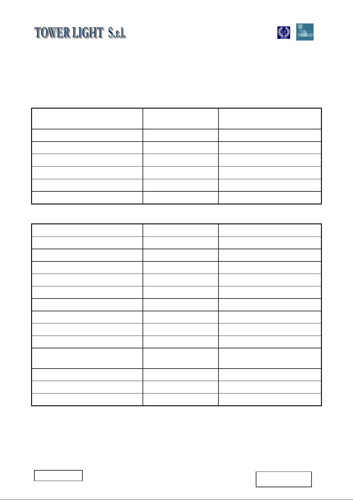
4. CARACTERÍSTICAS TÉCNICAS - TECHNICAL SPECIFICATION
4.1 GENERADOR - GENERATOR
Modelo Sincrónico -
Synchronous
Model
Tensión monofásica 10 kVA - 230 V Single phase voltage
Conexión monofásica auxiliar 4 kVA - 230 V Single phase auxiliary
Frecuencia 50 Hz Frequency
Cos ϕ0,8 Cos
ϕ
Clase de aislamiento F Insulation class
Grado de protección IP 23 Mechanical protection
4.2 MOTOR - ENGINE
Marca/Tipo de motor Kubota D1105 Make/Type
Número de cilindros 3 Number of cylinders
Cilindrada 1.123 cm3Displacement
Potencia 13,7 C.V. Power
Velocidad 1.500 r.p.m. Engine speed
Refrigeración Agua - Water Cooling
Combustible Diesel Fuel
Sistema de arranque Eléctrico - Electric Starting system
Capacidad del cárter 5,1 l Oil sump capacity
Consumo específico 265 gr/kWh Specific fuel consumption
Capacidad del depósito de
combustible
116 l Fuel tank capacity
Autonomía funcionando al 50% 96 h ~ 50% average operating hours
Nivel de ruido 90 Lwa Noise level
Batería 12 V - 44 Ah Battery
VT1 9 m 4x1.000W HALOGENURO METÁLICO
8TL006-09-00-00
28-08-2005
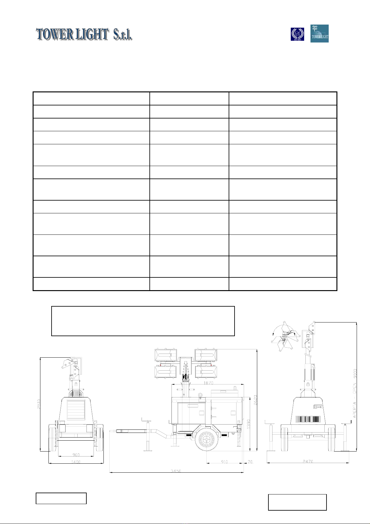
VERSIÓN SH
4.3 TORRE DE ILUMINACIÓN - LIGHTING TOWER
Altura máxima 9 m Maximum height
Elevación Hidráulica - Hidraulic Raising
Secciones 7 Section
Rotación 340° Rotation Section
Cable de subida y de bajada Cables Inox 133 –
Inox 133 wires
Raising and lowering cable
Cable eléctrico trenzado 7G1,5 mq Electrical coiled cable
Cable eléctrico del sistema de
iluminación
H07RN-F Electrical cable for the
lightingsystem
Carga máxima del cable 1.550 Kg Maximum cable load
Estabilidad máxima frente al
viento
110 Km/h Maximum wind stability
Dimensiones mínimas (Largo x
Ancho x Alto mm)
3.450 x 1.400 x 2.510 Minimum dimension
(L x W x H mm)
Dimensiones máximas
(Largo x Ancho x Alto mm)
3.450 x 2.470 x 9.000 Maximum dimension
(L x W x H mm)
Peso 1.068 Kg Weight
Dimensiones contando la máquina y el remolque con dos
ruedas y timón para remolcado lento
Dimensions with group wheels and rudder for slow towing

VT1 9 m 4x1.000W HALOGENURO METÁLICO
9TL006-09-00-00
28-08-2005
VERSIÓN SH
4.4 FOCO - FLOODLIGHT
Lámpara Halogenuro metálico
- Metal halide
Lamp
Potencia 4x1.000 W Power
Grado de protección IP 65 Degree of protection
Material de construcción del
cuerpo
Extrusión de
aluminio - Extrusion
of aluminium
Constructor material of the
body
Material de construcción del
portalámpara
Cerámica - Ceramic Constructor material
Dimensiones (Largo x Ancho x
Alto mm)
600 x 150 x 350 Dimension (L x W x H mm)
VT1 9 m 4x1.000W HALOGENURO METÁLICO
10 TL006-09-00-00
28-08-2005
VERSIÓN SH
1 2 3 4 5 6
12
7
8
9
10
11
16
15
14
13
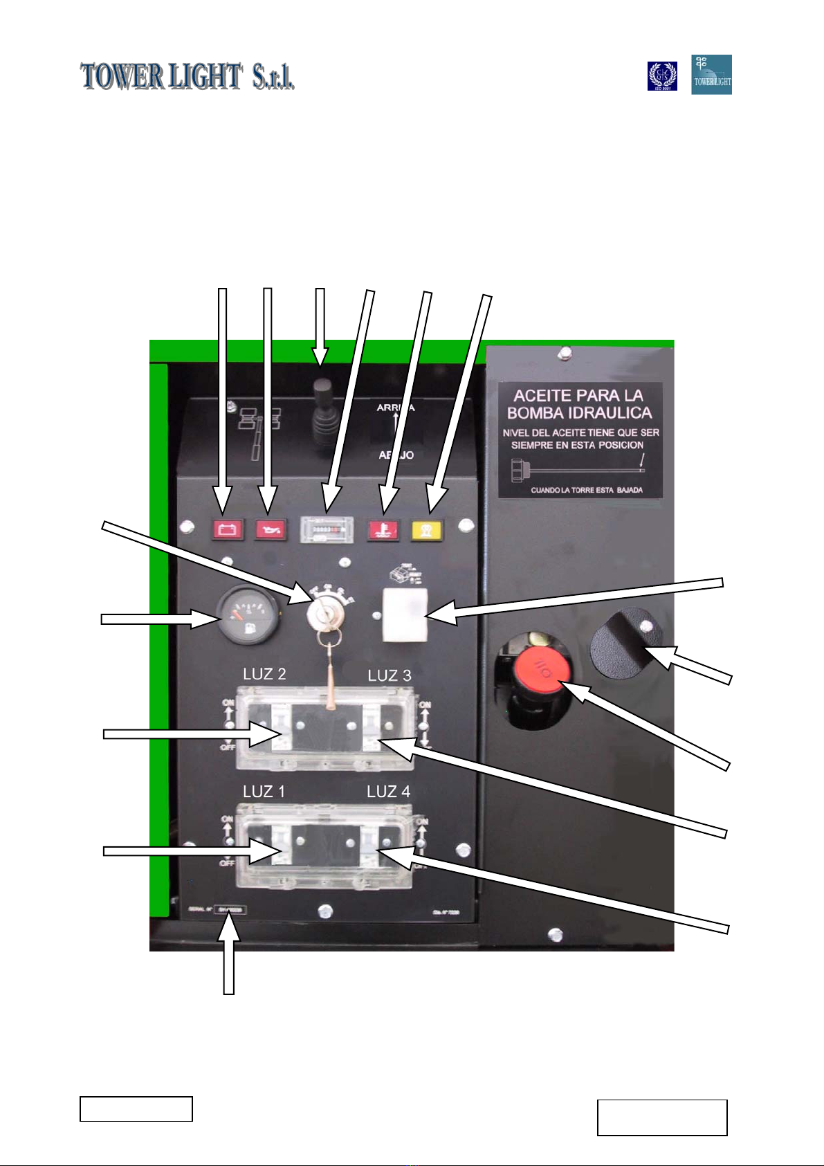
5. DESCRIPCIÓN DE LOS CONTROLES - CONTROLS DESCRIPTIONS

VT1 9 m 4x1.000W HALOGENURO METÁLICO
11 TL006-09-00-00
28-08-2005
VERSIÓN SH
Elemento
Items
Descripción Description
1 Indicador luminoso de carga de batería Battery charge signal lamp
2 Indicador luminoso de presión baja del
aceite
Low oil pressure signal lamp
3 Palanca de subida y bajada Rising and lowering lever
4 Contador de horas Hour meter
5 Indicador luminoso de temperatura alta
del agua
Hight water temperature signal lamp
6 Indicador luminoso de precalentamiento Preheater signal lamp
7 Interruptor diferencial automático de
40 A para fallo en la toma de tierra
40 A automatic earth leakage relay
8 Perno para bajar el mástil en caso de
emergencia
Lowering pin in case of emergency
9 Tapón hidráulico del depósito de aceite Hydraulic oil tank cap
10 Interruptor cortacircuito de 16 A para la
lámpara 3
16 A circuit breaker for lamp switch 3
11 Interruptor cortacircuito de 16 A para la
lámpara 4
16 A circuit breaker for lamp switch 4
12 Número de serie Serial number
13 Interruptor cortacircuito de 16 A para la
lámpara 1
16 A circuit breaker for lamp switch 1
14 Interruptor cortacircuito de 16 A para la
lámpara 2
16 A circuit breaker for lamp switch 2
15 Indicador del nivel de combustible Fuel gauge – Monitor fuel level
16 Llave de encendido/apagado Starting / stopping key
VT1 9 m 4x1.000W HALOGENURO METÁLICO
12 TL006-09-00-00
28-08-2005
VERSIÓN SH
17 18 19 20
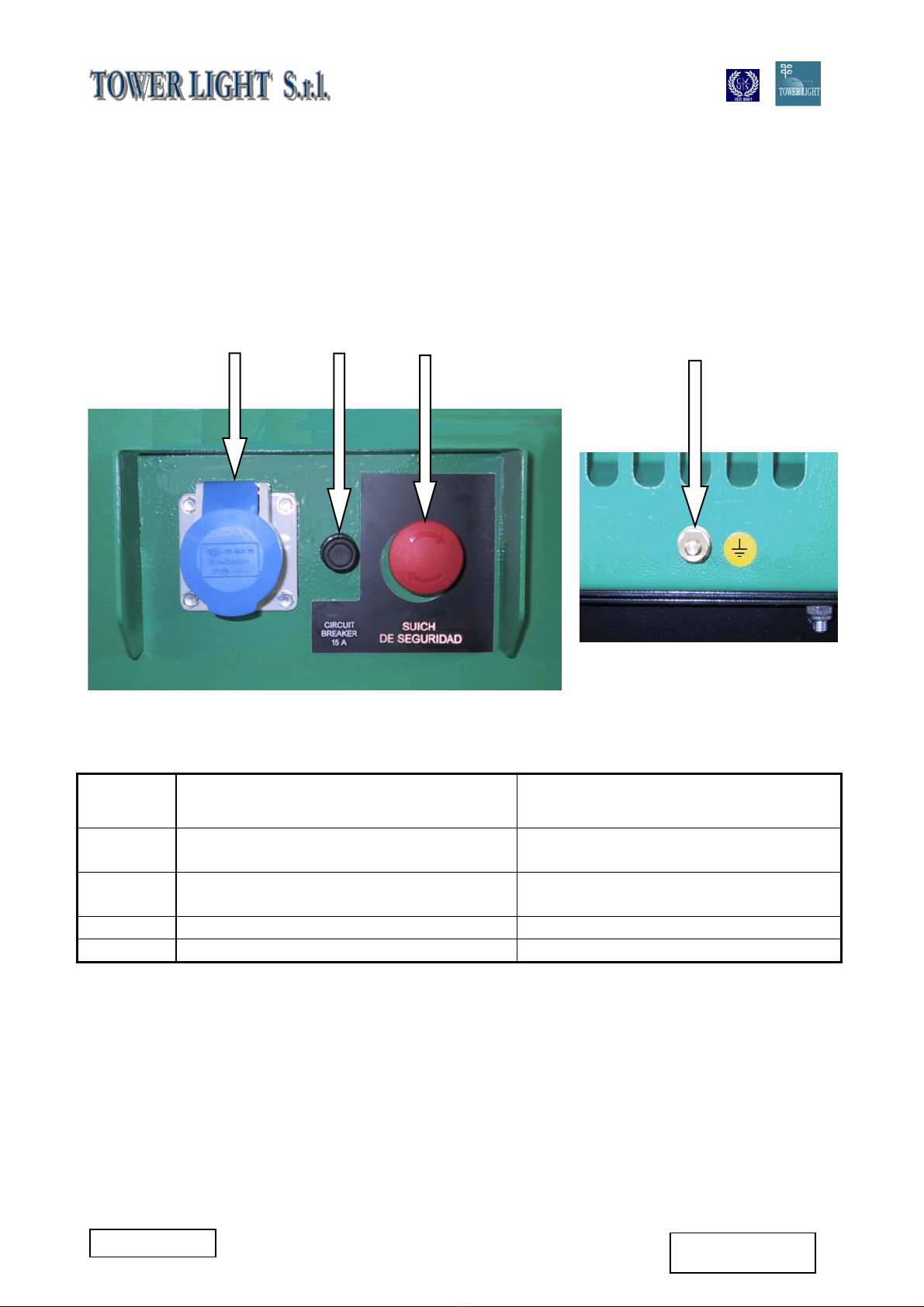
6. DESCRIPCIÓN DE LOS CONTROLES LATERALES - SIDE
CONTROLS DESCRIPTIONS
Elemento
Items
Descripción Description
17 Toma de corriente monofásica de
230 V 16 A 2p+T CEE
230 V 16 A 2p+T EEC single phase
socket
18 Botón cortacircuito de 15 A de la toma
de corriente de 230 V
15 A push button circuit breaker
control 230 V socket
19 Botón de parada de emergencia Emergency stop button
20 Conexión de la toma de tierra Earth clamp connection

VT1 9 m 4x1.000W HALOGENURO METÁLICO
13 TL006-09-00-00
28-08-2005
VERSIÓN SH
7. INSTRUCCIONES DE USO - OPERATING INSTRUCTIONS
7.1 CONECTAR LA BATERÍA - CONNECTING TO THE BATTERY
La máquina se entrega con la batería sin
conectar.
The machine is supplied with the battery
not connected.
Conecte la batería con los cables
suministrados prestando especial atención
a que la polaridad sea la correcta.
Connect the battery with cables alredy
predisposed making attention the just
polarity.
7.2 CONEXIÓN A TIERRA - EARTH CONNECTION
Realice la conexión a tierra de la unidad
mediante el terminal de tierra (20).
Connect the unit to the earth, means of
the (20) clamp.
La conexión a tierra de la unidad debe
realizarse utilizando un cable de cobre con
una sección transversal mínima de 6 mm².
The unit must be connected to earth
using a copper cable with a minimum
cross-section of 6 mm².
El fabricante no será responsable de
ningún tipo de daño causado por un fallo
en la conexión a tierra de la máquina.
The manufacturer is not responsible for
any damage caused by failure to earth
the system.
7.3 ENCENDER EL MOTOR - ENGINE STARTING
La máquina se entrega con aceite de
motor, aceite hidráulico y agua en el
radiador.
The machine is supplied of engine oil,
hydraulic oil and water in the radiator.
Gire la llave de encendido (16)hasta la
primera posición; esto permite que las
bujías se vayan calentando, a la vez que
se enciende el indicador luminoso de
precalentamiento (6). Cuando el indicador
(6) se haya apagado, encienda el motor
girando completamente la llave (16) en el
sentido de las agujas del reloj.
Position the starting key (16)on the first
step to avoid the glow plugs preliminary
heating, warning light (6) burnt. When
warning light (6) is off, start the engine
moving key (16)completely clockwise.
Nota: Si el motor no se enciende, gire la
llave hasta la posición de apagado (OFF) y
espere 10 segundos antes de volver a
repetir la operación de encendido.
Note: If the engine falls to start, turn the
switch to the OFF position and wait 10
seconds before operating the starter
again.
Deje el motor en marcha durante unos 5
minutos para que se vaya calentando.
Let the engine to run for about 5 minutes
to warm it up.

VT1 9 m 4x1.000W HALOGENURO METÁLICO
14 TL006-09-00-00
28-08-2005
VERSIÓN SH
7.4 RODAJE - RUNNING IN
Durante las primeras 50 horas de
funcionamiento de la máquina no utilice
más del 70% de la potencia máxima
indicada en las características técnicas. De
este modo, conseguirá un rodaje
adecuado del motor.
For the first 50 hours of operation of the
machine do not employ more than 70% of
the maximum power indicated in the
technical specifications. In this way, a
proper engine running in is guaranteed.
7.5 USO DE LA MÁQUINA - USE OF MACHINE
Interruptor diferencial
La máquina está provista de un ELCB
(interruptor de fuga a tierra) (7) que
garantiza la protección del usuario contra
descargas eléctricas debidas al contacto
involuntario con alguna parte del circuito o
a fallos en el sistema de aislamiento.
Earth Leakage Circuit Breaker.
The product is equipped with an Earth
Leakage Circuit Breaker (ELCB) (7)
which guarantees user protection against
electric shocks due to unwanted contect
with live parts of the circuit or insulation
fault.
¡Atención!
Para garantizar el correcto funcionamiento
del ELCB, la máquina debe estar
conectada a tierra. La conexión a tierra
debe realizarse conforme a las
disposiciones de la norma CEI 364.
Warning!
In order to guarantee ELCB proper
operation, the product must be earthed.
Earthing connection must conform to IEC
364 standard.
Es posible utilizar la torre de iluminación y
al mismo tiempo estar cogiendo corriente a
través de la toma monofásica de 230 V -
16 A (17). Se recomienda no sobrepasar
las cifras que figuran en la placa, ya que, si
no, saltará el cortacircuito (18).
It is possible at the same time to use the
lighting tower beacon and to capture
current from the single phase socket
230 V 16 A (17). It is recommended not to
exceed the plate data, in the contrary
case the circuit breaker (18) would
release.
Conecte la máquina al generador
utilizando clavijas que encajen en las
tomas de corriente y cables que estén en
excelentes condiciones.
Connect up to the generator using jacks
that fit the outlets and cables in excellent
condition.
La sección mínima de los cables de
conexión debe determinarse teniendo en
cuenta la tensión, la potencia instalada y la
distancia entre la fuente y el lugar de la
utilización.
The minimal section of connection cables
must be choose in relationship on the
tension, to the installed power and the
distance between source and uses.

VT1 9 m 4x1.000W HALOGENURO METÁLICO
15 TL006-09-00-00
28-08-2005
VERSIÓN SH
7.6 PARAR EL MOTOR - STOPPING THE ENGINE
Desconecte la carga conectada. Disconnect the utilizer.
Espere aproximadamente 1 minuto antes
de girar la llave (16) hasta la posición de
parada.
Wait approx. 1 minute, then turn the
starting key (16) to the stop position.
En caso de emergencia es posible parar la
máquina pulsando el botón de parada de
emergencia (19).
In emergency case is possible to stop the
group pressing the stop button(19).
7.7 ALARMAS DEL GENERADOR - GENERATOR ALARMS
El grupo electrógeno está dotado de una
protección que apaga la máquina después
de que alguna alarma indique que existe
un problema. Cuando ya se ha
solucionado el problema, el grupo
electrógeno vuelve a funcionar con
normalidad.
The generating set fitted have a
protection that turn off the machine the
shown after alarm. When the faulty
condition has been removed the
generating set return to at the normal
operations.
Presión baja del aceite. Low oil pressure.
Esta alarma salta cuando la presión del
aceite del motor es demasiado baja; se
enciende la luz del indicador (2).
Compruebe el nivel del aceite del motor.
Triggered when the engine oil pressure is
too low, the light comes on (2). Check the
engine oil level.
Temperatura alta del agua. High water temperature.
Esta alarma salta cuando la temperatura
del agua del motor es demasiado alta; se
enciende la luz del indicador (5).
Compruebe el nivel del agua del motor.
Triggered when the engine water
temperature is too high, the light comes
on (5). Check the engine water level.
La batería no tiene carga. No battery charge.
Esta alarma salta cuando el motor de
arranque no carga la batería o cuando a la
batería se le agota la carga; se enciende la
luz del indicador (1). Compruebe el motor
de arranque y la batería.
Triggered when the starting motor don’t
not charge the battery or the battery does
not hold loads, the light comes on (1).
Check the starting engine and the battery.
Nivel de combustible bajo. Low fuel level.
Esta alarma salta cuando el indicador del
nivel de combustible entra en reserva; se
enciende la luz del indicador (15). Llene el
depósito de combustible.
Triggered when fuel level probe, the light
comes on (15). Fill up the tank with the
fuel.

VT1 9 m 4x1.000W HALOGENURO METÁLICO
16 TL006-09-00-00
28-08-2005
VERSIÓN SH
8. INSTRUCCIONES PARA EL USO DE LA TORRE DE ILUMINACIÓN -
INSTRUCTION FOR USE OF THE LIGHTING TOWER
Coloque la máquina de forma que quede
totalmente horizontal con la ayuda de los
cuatro estabilizadores laterales.
Place in plane the group through the four
lateral stabilizers.
Cuando haya encendido el motor, coloque el
interruptor diferencial en la posición ON (7),
levante el mástil con la palanca (3), encienda
el interruptor de la primera lámpara (13) y
deje que se caliente durante 2 minutos; deje
que cada lámpara se caliente durante 2
minutos antes de encender el interruptor de
la siguiente lámpara (10-11-14).
When the engine is start up, position the
earth leakage circuit breaker on ON (7
)
,
raising the bracket through the lever (3),
switch on (13)first lamp and allow 2
minutes for it to warm up, allow each lamp
to warm up for 2 minutes before operation
the next lamp (10-11-14).
Oriente el haz de luz rotando el mástil hasta
la posición deseada. El bloque mecánico
permite una rotación de hasta 340º.
Rotate the bracket on the opportune way
to place the beam.The mechanical block
concurs to stop the spin to 340°.
La presión del aceite hidráulico que sirve
para subir o bajar el mástil se acciona
mediante una bomba mecánica que sólo
funciona cuando el motor está encendido.
The pressure of the hydraulic oil that
serves to make up and down the bracket
is set in action through a mechanical
pump that only works when the engine is
start up.
Verifique periódicamente el nivel del aceite
hidráulico abriendo el tapón del depósito. Si
la cantidad de aceite ha disminuido o si ha
de sustituir el aceite por otro, utilice sólo
aceites hidráulicos con el índice de
viscosidad más alto y que puedan utilizarse
en una franja de temperaturas de + 46°C a–
46°C. Nosotros aconsejamos la utilización
del aceite Shell Tellus TX 46.
Extract the filler cap to verify periodically
the level of the hydraulic oil. In case of
substitution or lessening use only
hydraulic oils with highest index of
viscosity and adapt to use for + 46°C to –
46°C temperatures than We advised the
oil (Shell Tellus Oils TX 46).
8.1 DIAGRAMA DE LA COBERTURA DE ILUMINACIÓN - LIGHTING FOOT PRINT DIAGRAM
ÁREA ILUMINADA – ILLUMINATED AREA
4.200 m²
VT1 9 m 4x1.000W HALOGENURO METÁLICO
17 TL006-09-00-00
28-08-2005
VERSIÓN SH
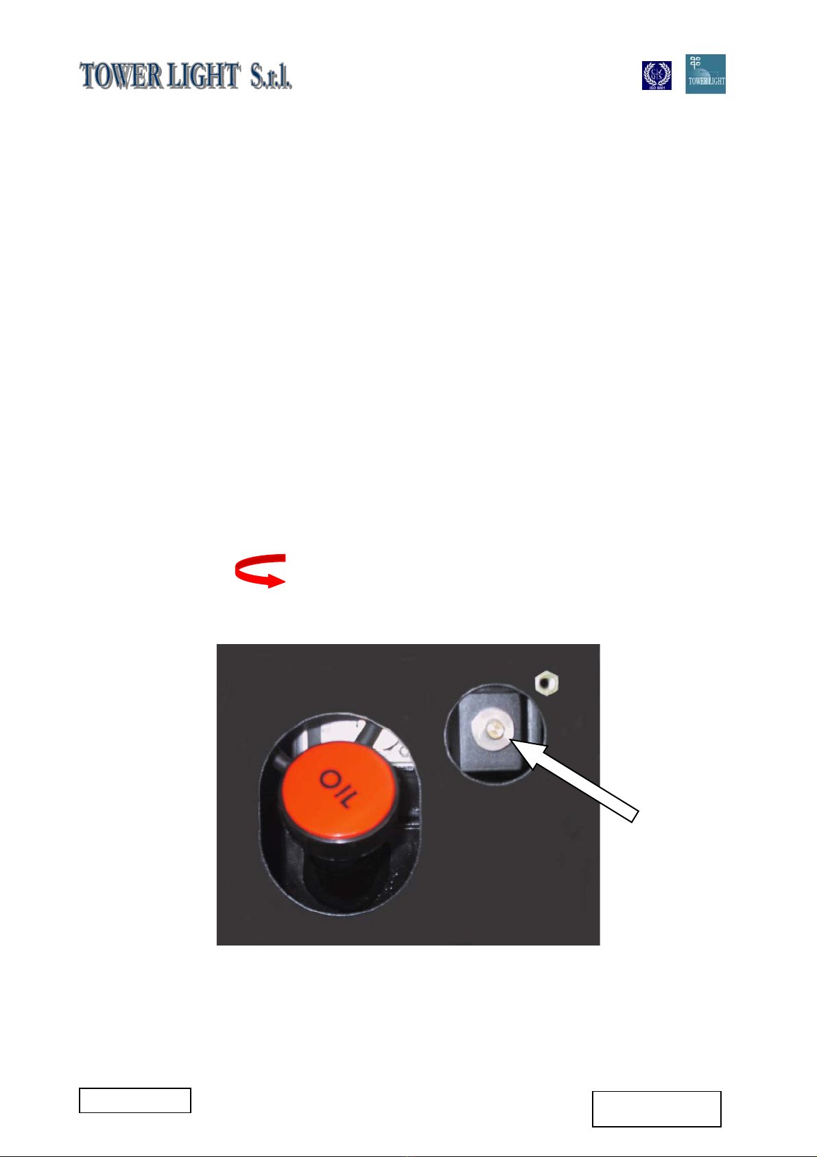
9. BAJAR EL MÁSTIL EN CASO DE EMERGENCIA - LOWERING
HANDLE BAR BRACKET IN CASE OF EMERGENCY
¡¡¡ATENCIÓN!!! ATTENTION !!!
En caso de que el motor se estropee
cuando el mástil está izado, se puede
bajar la torre haciendo girar hacia la
izquierda el perno (Fig. A) que regula el
flujo manual del aceite en el interior del
cilindro. Cuando el mástil esté totalmente
bajado y el motor ya funcione con
normalidad hay que volver a colocar el
perno en la posición original para
garantizar la correcta utilización posterior
de la máquina. UNA VEZ HECHO ESTO,
LA TORRE DE ILUMINACIÓN ESTÁ
LISTA PARA VOLVER A SER UTILIZADA
CON TOTAL NORMALIDAD.
When the mast is raised, in case of the
damage of the engine, is possible to
came down the tower unscrewing in left
direction the particular pin (Fig A) that
regulated the manual flow of oil inside the
cylinder. When the bracket is completely
come down, and the engine is sheltered,
is necessary to screwing the pin in the
originally position to guarantee
subsequently the correct use of the
machine. AT THIS TIME, THE TOWER
LIGHT, IS ABSOLUTELY READY TO
RETAKE THE NORMAL RUNNING.
Sentido de rotación del perno
Way of rotation of the pin
(Fig. A)

VT1 9 m 4x1.000W HALOGENURO METÁLICO
18 TL006-09-00-00
28-08-2005
VERSIÓN SH
10. CAUSAS DE UN BAJO RENDIMIENTO DEL MOTOR - CAUSES OF
ENGINE POOR PERFORMANCE
Para mantener el motor en perfectas
condiciones le aconsejamos que lleve a
cabo las operaciones de mantenimiento
indicadas en el manual del usuario de “Uso
y mantenimiento” del fabricante del motor.
Un mantenimiento descuidado puede
provocar una reducción de la vida útil de la
máquina y un bajo rendimiento del motor.
In order to preserve the engine
performance strongly suggests following
the maintenance operations and the
maintenance schedule reported in the
engine manufacturer “Use and
maintenance” user manual. Poor
maintenance could result in a shorter
period of operation and in performance
decrease.
LIMPIEZA DEL FILTRO DE COMBUSTIBLE CLEANING THE FUEL FILTER POT
Limpie el filtro de combustible cada 100
horas de actividad. Esta operación debe
llevarse a cabo en un lugar limpio para
evitar la entrada de polvo.
Every 100 hours of operation, clean the
fuel filter. And so on in a clean place to
prevent dust intrusion.
Operaciones: Operations:
•Cierre la válvula del filtro de combustible
(fig. 1 n° 1, posición B).
•Close the fuel filter chock (fig. 1 n°1,
position B).
•Saque el tapón y enjuague el interior con
gasóleo.
•Remove the top cap, and rinse the
inside with diesel fuel.
•Saque el filtro (fig. 1 n° 2) y enjuáguelo
con gasóleo.
•Take out the element (fig. 1 n°2), and
rinse it with diesel fuel.
•Después de limpiar el filtro de
combustible, vuelva a colocarlo en su
sitio evitando que se manche de polvo y
suciedad.
•After cleaning, reinstall the fuel filter,
keeping out of dust and dirt.
•Purgue la bomba de inyección. •Air-bleed the injection pump.
SUSTITUCIÓN DEL CARTUCHO DEL
FILTRO DE COMBUSTIBLE
FUEL FILTER CARTRIDGE
REPLACEMENT
Sustituya el cartucho del filtro de
combustible (fig. 3 n° 1) por uno nuevo más
o menos cada 400 horas de actividad.
Replace the fuel filter cartridge (fig. 3 n°1)
with new one every 400 operating hours
or so.
Operaciones: Operations:
•Aplique una ligera capa de gasóleo en la
junta de culata y coloque el cartucho en
posición apretando con la mano.
•Apply fuel oil thinly over the gasket and
tighten the cartridge into position hand-
tight.
•Finalmente, saque el aire del sistema. •Finally vent the air.

VT1 9 m 4x1.000W HALOGENURO METÁLICO
19 TL006-09-00-00
28-08-2005
VERSIÓN SH
IMPORTANTE: Cambie periódicamente el
cartucho del filtro de combustible para evitar
que la tobera de inyección o el émbolo de la
bomba de inyección se estropeen debido a
la presencia de suciedad en el combustible.
IMPORTANT: Replace the fuel filter
cartridge periodically to prevent wear of
the fuel injection pump plunger or the
injection nozzle due to dirt in the fuel.
ACEITE DEL MOTOR ENGINE OIL
•PRECAUCIÓN: Para evitar daños
personales, asegúrese de parar el motor
antes de comprobar el nivel del aceite y
antes de cambiar el aceite y el cartucho
del filtro de aceite.
•CAUTION: To avoid personal injury,
be sure to stop the engine before
checking the oil level, changing the oil
and the oil filter cartridge.
•NOTA: No olvide inspeccionar el motor
colocándolo en un lugar horizontal. Si lo
coloca en un lugar inclinado, no será
posible medir correctamente la cantidad
de aceite que hay.
•NOTE: Be sure to inspect the engine,
locating it on a horizontal place. If
placed on gradients, accurately, oil
quantity may not be measured.
COMPROBACIÓN DEL NIVEL DE ACEITE
Y AÑADIDURA DE ACEITE DEL MOTOR
CHECKING LEVEL AND ADDING
ENGINE OIL
Operaciones: Operations:
•Compruebe el nivel de aceite del motor
antes de encenderlo o 5 minutos después
de haberlo apagado.
•Check the engine oil level before
starting or more than five minutes after
stopping.
•Saque la varilla indicadora del nivel de
aceite (fig. 4 n° 2), límpiela bien con un
paño y vuelva a colocarla.
•Detach the oil level gauge (fig. 4 n°2),
wipe it clean and reinstall it.
•Vuelva a sacar la varilla y compruebe el
nivel de aceite.
•Take the oil level gauge out again, and
check the oil level.
•Si el nivel de aceite es demasiado bajo,
saque el tapón del filtro del aceite (fig. 4
n° 1) y añada aceite hasta llegar al nivel
recomendado (fig. 4 A).
•If the oil level is too low, remove the oil
filter plug (fig. 4 n°1) and add new oil to
the prescribed level (fig. 4 A).
•Después de añadir aceite, espere un
poco más de 5 minutos y vuelva a
comprobar el nivel de aceite. Este tiempo
es el que tarda el aceite en bajar hasta el
cárter.
•After adding oil, wait more than 5
minutes and check the oil level again.
It takes same time for the oil to come
down to the oil pan.
CAMBIO DEL ACEITE DEL MOTOR CHANGING ENGINE OIL
•Cambie el aceite del motor después de
las primeras 50 horas de actividad y,
luego, cada 200 horas.
Change oil after the initial 50 hours of
operation and every 200 hours thereafter.

VT1 9 m 4x1.000W HALOGENURO METÁLICO
20 TL006-09-00-00
28-08-2005
VERSIÓN SH
Operaciones: Operations:
•Retire el tapón de drenaje que hay en la
parte derecha de la estructura y drene
todo el aceite antiguo. El drenaje del
aceite se realiza de forma más fácil y
completa cuando el motor está caliente.
•Remove the drain plug on the right
side of the frame and drain all the old
oil. Drain oil easier and completely
while the engine is hot.
•Añada nuevo aceite de motor hasta el
límite superior de la varilla indicadora
del nivel de aceite.
•Add new engine oil up to the upper
limit of the oil level gauge.
SUSTITUCIÓN DEL CARTUCHO DEL
FILTRO DE ACEITE
REPLACING THE OIL FILTER
CARTRIDGE
•PRECAUCIÓN: Para evitar daños
personales, asegúrese de parar el motor
y de dejarlo enfriar antes de cambiar el
cartucho del filtro de aceite; el aceite
puede estar caliente y puede quemarse.
•CAUTION : To avoid personal injury
be sure to stop the engine before
changing the oil filter cartridge and
allow engine to cool down sufficiently;
oil can be hot and can burn.
Operaciones: Operations:
•Cambie el cartucho del filtro de aceite
(fig. 5 n° 1) cada 200 horas de actividad.
•Replace the oil filter cartridge (fig. 5
n°1) every 200 hours of operation.
•Retire el cartucho usado del filtro de
aceite con una llave de filtro.
•Detach the old oil filter cartridge with a
filter wrench.
•Aplique una capa de aceite a la junta de
culata para el nuevo cartucho.
•Apply a film of oil to the gasket for the
new cartridge.
•Coloque el cartucho con la mano.
Cuando la junta de culata entre en
contacto con la superficie estanca,
apriete el cartucho con la mano hasta
que quede bien fijado. Si aprieta el
cartucho con la llave de filtro, el
cartucho quedará demasiado apretado.
•Screw in the cartridge by hand. When
the gasket contacts the seal surface,
tighten the cartridge enough by hand.
Because, if you tight the cartridge with
wrench, it will be tightened too much.
•Después de sustituir el cartucho, el nivel
de aceite del motor suele bajar un poco.
Por esta razón, encienda un rato el
motor y compruebe que no haya
ninguna pérdida de aceite a través de la
junta estanca antes de comprobar el
nivel de aceite del motor. Añada aceite
si es necesario.
•After the new cartridge has been
replaced, the engine oil level normally
decreases a little. Thus, run the engine
for a while and check oil leaks through
the seal before checking the engine oil
level. Add oil if necessary.
Table of contents
Other Tower Light Lighting Equipment manuals


