TOWNGAS Mia Cucina CUBE 900 User manual


安裝及使用說明書
Instruction on Installation and Use
CUBE 900

burning gas or other fuels.
The flaming of foods beneath the hood itself is
strictly prohibited.
Exposed flames are detrimental to the filter and
may cause a fire risk, and must therefore be
avoided in all circumstances.
Any frying must be done with care in order to
make sure that the oil does not overheat and
ignite.
Accessible parts of the hood may become hot
when used with cooking appliance.
With regards to the technical and safety
measures to be adopted for fume discharging it
is important to closely follow the regulations
provided by the local authorities.
The hood must be regularly cleaned on both the
inside and outside (AT LEAST ONCE A MONTH).
This must be completed in accordance with the
maintenance instructions provided in this
manual. Failure to follow the instructions
provided in this user guide regarding the
cleaning of the hood and filter will lead to the risk
of fires.
Do not use or leave the hood without the lamp
correctly mounted due to the possible risk of
electric shocks.
This appliance is marked according to the
European directive 2002/96/EC on Waste
Electrical and Electronic Equipment (WEEE). By
ensuring this product is disposed of correctly,
you will help prevent potential negative
consequences for the environment and human
health, which could otherwise be caused by
inappropriate waste handling of this product.
The symbol on the product, or on the
documents accompanying the product,
indicates that this appliance should not be
treated as household waste. Instead it should be
taken to the appropriate collection point for the
recycling of electrical and electronic equipment.
Disposal must be carried out in accordance with
local environmental regulations for waste
disposal.
For further detailed information regarding the
process, collection and recycling of this product,
please contact Environmental Protection
Department.
Thank you for choosing Mia Cucina product. It is
supplied by Towngas Company. For any
enquiries about installation, operation and
service, please call our customer service hotline:
2880 6988.
Closely follow the instructions set out in this
manual. All responsibility, for any eventual
inconveniences, damages or fires caused by not
complying with the instructions in this manual, is
declined. The extractor hood has been designed
exclusively for domestic use.
The hood may look different to that illustrated
in the drawings in this booklet. The instructions
for use, maintenance and installation, however,
remain the same.
! It is important to conserve this booklet for
consultation at any moment. In the case of sale
or relocation, make sure it is together with the
product.
! Read the instructions carefully: there is
important information about installation, use
and safety.
! Do not carry out electrical or mechanical
variations on the product or on the discharge
conduits.
Caution
WARNING! Do not connect the appliance to the
mains until the installation is fully complete.
Before any cleaning or maintenance operation,
disconnect hood from the mains by removing the
plug or disconnecting the mains electrical
supply.
Always wear work gloves for all installation and
maintenance operations.
The appliance is not intended for use by children
or persons with impaired physical, sensorial or
mental faculties, or if lacking in experience or
knowledge, unless they are under supervision or
have been trained in the use of the appliance by
a person responsible for their safety.
This appliance is designed to be operated by
adults. Children should not be allowed to
tamper with the controls or play with the
appliance.
Never use the hood without securely mounted!
The hood must NEVER be used as a support
surface.
The premises where the appliance is installed
must be sufficiently ventilated, when the kitchen
hood is used together with other gas combustion
devices or other fuels.
The ducting system for this appliance must not
be connected to any existing ventilation system
which is being used for any other purpose such
as discharging exhaust fumes from appliances
EN - Instruction on mounting and use
1

Installation
Fig. 1-2
The minimum distance between the supporting
surface for the cooking equipment on the hob
and the lowest part of the range hood must not
be less than 50cm from electric cookers and
65cm from gas or mixed cookers.
If the instructions for installation for the gas hob
specify a greater distance, this must be adhered to.
Electrical connection
The mains power supply must correspond to the
rating indicated on the plate situated inside the
hood. If provided with a plug connect the
hood to a socket in compliance with current
regulations and positioned in an accessible area,
after installation. If it is not fitted with a plug
(direct mains connection) or if the plug is not
located in an accessible area, after installation,
apply a double pole switch in accordance with
standards which assures the complete
disconnection of the mains under conditions
relating to over-current category III, in
accordance with installation instructions.
Warning! Before re-connecting the hood circuit
to the mains supply and checking the efficient
function, always check that the mains cable is
correctly assembled.
Mounting
Wall plugs are provided to secure the hood to
most types of walls. However, a qualified
technician must verify suitability of the materials
in accordance with the type of wall. The wall
must be strong enough to take the weight of the
hood. Do not tile or glue this appliance to the
wall. It must be mounted on wall surface by
screws.
Preliminary information for installation of the
hood:
Disconnect the hood during electrical connec-
tion, by turning the home mains switch off.
Remove the fat/s filter/s and the carbon filter
frame.
Do not fix chimney flue to furniture or hanging
cabinet unless the chimney flue can be easily
removed, in case maintenance is ever required.
Use
The hood is supplied to be used for ducting
installation. Filter version is optional (carbon
filter not provided, to be purchased separately).
Ducting version
The hood is equipped with a top air outlet for
discharge of fumes to the outside.
Attention! The exhausting pipe is not supplied
and must be purchased apart.
Diameter of the exhausting pipe must be equal
to that of the connection ring.
In the horizontal runs the exhausting pipe must
be slightly slanted (about 10°) and directed
upwards to vent the air easily from the room to
the outside.
Attention! If the hood is supplied with active
charcoal filter, then it must be removed.
Connect the hood and discharge holes on the
walls with a diameter equivalent to the air outlet
(connection flange).
Using the tubes and discharge holes on walls
with smaller dimensions will cause a diminution
of the suction performance and a drastic
increase in noise.
Any responsibility in the matter is therefore
declined.
! Use a duct of the minimum indispensible
length.
! Use a duct with as few elbows as possible
(minimum elbow angle: 90°).
! Avoid drastic changes in the duct cross-
section.
! Use a duct with inner surface as smooth as
possible.
! The duct must be made of certified material.
Filter version
Should it not be possible to discharge cooking
fumes and vapours to the outside, the hood can
be used in the filter version, fitting an activated
carbon filter and the deflector on the support
(bracket), fumes and vapours are recycled
through the top grille by means of an exhaust
pipe connected to the top air outlet and the
connection ring mounted on the deflector
(exhaust pipe and pipe fixing clamps not
provided).
2

18.Apply the chimney stacks and fasten them at
the top to the chimney support with 2 screws
(fig.26).
19.Slide the bottom section of the chimney
down until it completely covers the suction
unit and slots into the housing provided on
top of the hood.
Remount the carbon filter frame and the grease
filter and check the perfect functioning of the
hood.
Description of the hood
1. Control panel
2. Grease filter
3. Grease filter release handle
4. Halogen lamp
5. Vapour catcher
6. Telescopic chimney
Operation
Use the high suction speed in cases of concen-
trated kitchen vapours. It is recommended that
the cooker hood suction is switched on for 5
minutes prior to cooking and to leave in
operation during cooking and for another 15
minutes approximately after terminating
cooking.
Installation procedures
1. Using a pencil, draw a line on the wall,
extending up to the ceiling, to mark the
centre. This will facilitate installation (fig.1).
2. Rest the drilling template against the wall:
the vertical centre line printed on the drilling
template must correspond to the centre line
drawn on the wall, and the bottom edge of
the drilling template must correspond to the
bottom edge of the hood: bear in mind that,
when installation is complete, the underside
of the hood must be at least 50 cm above the
cooker top in the case of electric cookers,
and at least 65 cm above the cooker top in
the case of gas or mixed cookers (fig.2).
3. Drill at the point marked (Ø8mm), insert wall
dowel and fix a 5x45mm mounting screw
(fig.3-4).
4. Apply the flues support bracket to the wall
adherent to the ceiling, use the flues support
bracket as a perforation diagram (if present,
the small slot on the support must coincide
with the line drawn previously on the wall)
and mark two holes with a pencil. Make the
holes (Ø8mm), and insert 2 dowels.
Fix the chimney support bracket to the wall
using two 5x45mm screws (fig.5).
5. Make a hole for exhaust duct (fig.6-7).
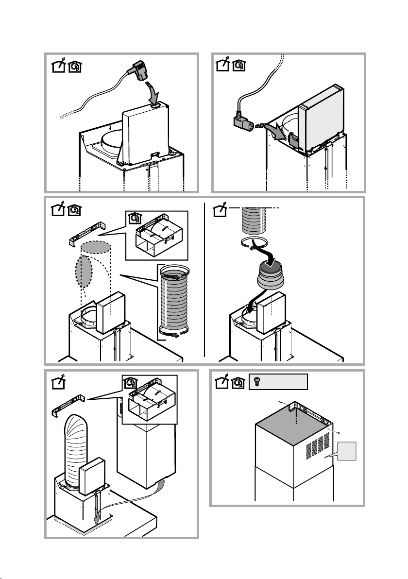
6. Slide electric control box to the front (if
necessary) and remove grease filter from the
hood (fig.10-11).
7. Hook the hood onto mounting screw (fig.12).
8. Adjust the horizontal position (fig.13).
9. Adjust the distance of the hood from the wall
(fig.14).
10.Referring to fig.15, mark screw fixing points
on the wall, then remove the hood.
11.Drill at the point marked (Ø8mm) and insert
wall dowel (fig.17).
12.Fix the hood into its final position on the wall
(fig.19).
13.Fix connection ring to the exhaust outlet with
2 screws (fig.20).
14.Use 2 screws to fix electric box to the top of
suction unit (fig.21-22).
15.Connect electric cable (fig.23), ensure the
electricity is disconnected.
16.Connect exhaust pipe (pipe and pipe clamps
not provided, to be purchased separately)
for discharge of fumes to the connection ring
located over the suction motor unit.
If the hood is to be used in ducting version,
the other end of the pipe must be connected
to a device expelling the fumes to the
outside. If the hood is to be used in filter
version, then fix the deflector to the chimney
support and connect the other end of the
pipe to the connection ring placed on the
deflector (fig.24-25).
17.Connect the electricity.
3
Maintenance
ATTENTION! Before performing any maintenance
operation, isolate the hood from the electrical
supply by switching off at the connector and
removing the connector fuse.
Or if the appliance has been connected through
a plug and socket, then the plug must be
removed from the socket.
Cleaning
The cooker hood should be cleaned regularly (at
least with the same frequency with which you carry
out maintenance of the grease filter) internally and
externally. Clean using the cloth dampened with
neutral liquid detergent. Do not use abrasive
products. DO NOT USE ALCOHOL!
WARNING: Failure to carry out the basic cleaning
recommendations of the cooker hood and the
filters may cause fire risks.
Therefore, we recommend observing these
instructions.
The manufacturer declines all responsibility for any
damage to the motor or any fire damage linked to
inappropriate maintenance or failure to observe
the above safety recommendations.
Grease filter
Fig. 11
This must be cleaned once a month (or when the
filter saturation signal is indicated) using non
aggressive detergents, either by hand or in the
dishwasher, which must be set to a low tempera-
ture and a short cycle.
When washed in a dishwasher, the grease filter
may discolour slightly, but this does not affect its
filtering capacity.
To remove the grease filter, pull the spring
release handle.
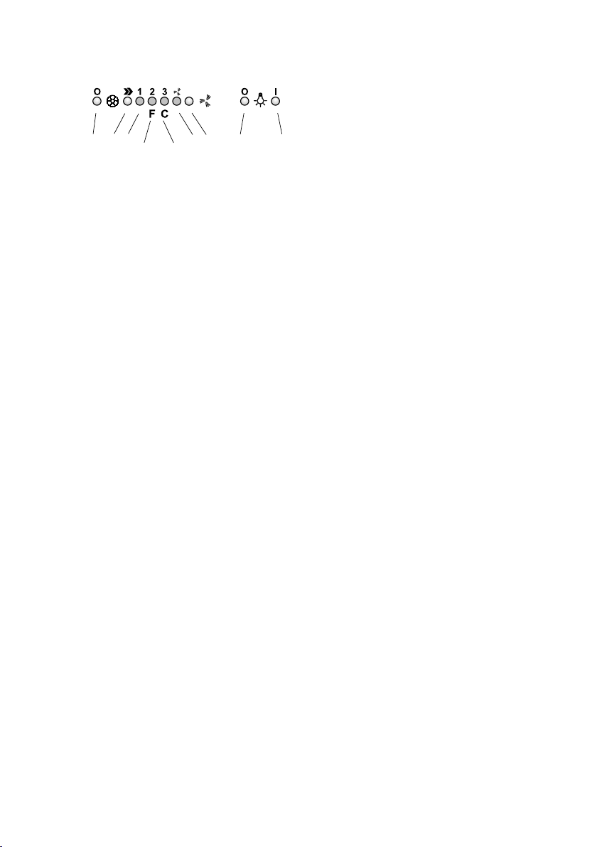
Functioning
1. Motor OFF button
2. ON button and motor speed selection button
1 - 2 - 3 - 1 - 2 - . . . .
3. Speed 1 LED
4. Speed 2 LED and metal grease filter
saturation LED (in this latter case, the LED
will flash - See instructions on grease filter
cleaning).
Once the grease filters have been cleaned,
press button 1 for about 3 seconds until you
hear the acoustic signal (beep): the LED 4 will
now stop flashing.
5. Speed 3 LED and active carbon filter
saturation LED (in this latter case, the LED
will flash - See instructions on active carbon
filter replacement).
Once you have replaced the charcoal filter,
press button 1 for about 3 seconds until you
hear the acoustic signal (beep). LED 5 will
now stop flashing.
Warning!
The active carbon filter saturation LED is not
activated.
In order to activate the active carbon filter
saturation indicator, press buttons 2 and 7
simultaneously for 3 seconds. Initially, only
LED 4 will flash, then after the 3 seconds
have passed, LED 5 will also start flashing,
indicating that the active carbon filter
saturation control system is active.
To switch off the system, re-press the same
two buttons: after 3 seconds LED 5 will stop
flashing and the device will be switched off.
6. Intensive speed LED
7. Intensive speed ON switch
This speed should be used when the concen-
tration of cooking fumes or odours is
particularly strong (for example when frying,
cooking fish etc.).
The fast speed will run for about 5 minutes
and then return to the speed previously set
automatically (1, 2 or 3), or switch off if no
speed was selected.
To turn off the fast speed, before the end of
the 5 minutes, press button 1 or button 2.
8. OFF lamp button
9. ON lamp button
If the hood fails to operate correctly, briefly
disconnect it from the mains power supply for
about 5 sec. by pulling out the plug. Then plug it
in again and try once more before calling for
service.
4
12 3
456 7 89

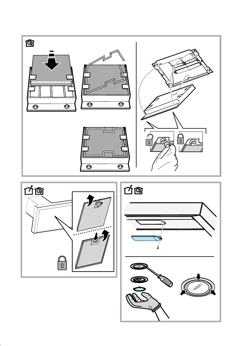
Replacing lamps
Fig. 29
Disconnect the hood from the electricity.
Warning! Prior to touching the light bulbs ensure
they are cooled down.
1. Extract the lamp cover by levering it off with
a small screwdriver or similar tool.
2. Replace the damaged light bulb.
Only use halogen bulbs of 20W max (G4),
making sure you do not touch them with your
hands.
3. Close the lamp cover (it will snap shut).
If the lights do not work, make sure that the
lamps are fitted properly into their housings
before you call for technical assistance.
Charcoal Filter (filter version only)
Fig. 27
It absorbs unpleasant odours caused by cooking.
The activated charcoal filter can be one of these
types:
●
Washable activated charcoal filter.
●
NON-washable activated charcoal filter.
Washable activated charcoal filter
The charcoal filter can be washed once every two
months (or when the filter saturation indication is
lit) using hot water and a suitable detergent, or in a
dishwasher at 65°C (if the dishwasher is used,
select the full cycle function and leave dishes out).
Eliminate excess water without damaging the filter,
then remove the mattress located inside the plastic
frame and put it in the oven for 10 minutes at
100°C to dry completely. Replace the mattress
every 3 years and when the cloth is damaged.
NON-washable activated charcoal filter
The saturation of the charcoal filter occurs after
more or less prolonged use, depending on the type
of cooking and the regularity of cleaning of the
grease filter.
In any case it is necessary to replace the cartridge
at least every four months.
The charcoal filter may NOT be washed or regener-
ated.
Assembly
Hook the charcoal filter at the back on the metal
tongue of the hood first, then on the front with the
two knobs.
Disassembly
Remove the charcoal filter by turning the knobs
fixing it to the hood by 90°.
5

6
多謝選用 Mia Cucina 產品,它是由煤氣公
司提供,有關安裝、使用和維修的查詢,請
致電我們的客戶服務熱線28806988。
安裝及使用說明
務請恪守本說明書所載一切指示,否則本公
司不會對所造成的不便、損毀或火警負上任
何責任。本抽油煙機只適合家居使用。
本說明書內的圖片旨在說明如何使用本產品
,因此或與實物有異,而不影響有關安裝、
使用及保養的指示。
! 安裝後,請留把本說明書妥為保存,作日
後參考,若轉移安裝時,也當帶同它。
! 請細閱本說明書,以便取得有關安裝、使
用及安全的資訊。
! 切勿對產品電機和煙道作出改動。
警告!
警告!抽油煙機完成安裝後,才可以接駁電源。
進行任何清潔或保養工作前,必須切斷電源。
進行安裝和保養工作時,務請配戴工作手套。
切勿讓兒童使用本抽油煙機,除非經由成人
監督下使用,殘障人士或有精神障礙的成人
均不適宜使用本機。
本抽油煙機乃設計予成人使用,切勿任由兒
童把玩或觸碰控制部份。
煙道安裝妥當前,切勿使用本抽油煙機。
切勿將抽油煙機作支撐用途。
當同時使用抽油煙機與其他燃氣爐具,必須
確保通風良好。
本抽油煙機不可與其他燃氣爐具共用排煙管道。
切勿在抽油煙機下採用以烈酒燃點食物的烹
調方法。
避免讓火焰觸及抽油煙機,以免損壞濾網及
釀成火警。因此,不應在抽油煙機下進行燒
烤之類的烹調方式。
由於食油在高熱下會有搶火現象,故此在進
行煎炸時,應特別小心。
當煮食時,抽油煙機可觸碰的表面會較熱。
排放油煙時,務請遵守當地有關技術及安全
規定的條例。
應經常清潔抽油煙機內外(每月至少一次)。
如未有按指示清潔抽油煙機及濾油網,或會
釀成火警。因此,務請恪守該等指引。
如未確定燈泡已經安裝妥當,請不要使用抽
油煙機,以免發生觸電危險。
本抽油煙機符合歐盟指引
(WEEE)2002/96/EC 的規定。這標誌 表示
本產品應與其他家居廢物分開棄置。因此,
當棄置本產品時,請將之運往專門處理電器
及電子產品的廢物回收中心,或在購買新爐
具時送往有關之零售店。把廢物分類回收、
處理或採用環保方式棄置,有助減低對自然
環境和人類健康的影響,並可把材料循環再
用。
欲知更多有關廢物收集制度的資料,可向環
保署查詢。
使用
本抽油煙機設定為排煙模式(過濾模式的裝
置須另外購買)。
排煙模式
抽油煙機頂部設有排氣口以便把油煙排到室
外。
注意:排氣所需的排氣管及配件須另外購買
,
喉氣直徑需與排氣接口一致
。
水平安裝管道應微斜向上(約10度)以便將
煙氣排出室外。
注意:如抽油煙機附有活性碳濾隔,需把它
移除。使用適當口徑排氣管連接各排氣出
口。使用較細口徑排氣管會減低排氣量及增
加噪音。
因使用不當喉管對排氣功能的影響,本公司
不會負責。
!按需要設計排氣管長度。
!避免使用過量彎曲位。
!避免喉管摺曲變形。
!使用平滑喉管較佳。
!使用合規格排氣管供安裝。
過濾模式
如無法把油煙排到戶外,可加上活性炭濾隔,
並在機頂支架安裝導流裝置,令抽油煙機以過
濾模式運作,即把濾走油煙後的空氣經由頂部
的排氣口及導流裝置,然後從煙道頂端兩側柵
格送回室內(排氣所需的排氣管及其固定環須
另外購買)。

7
安裝
圖1-2
如使用電熱板或電爐,抽油煙機應距離爐面
至少50厘米;如屬氣體爐具或混合式爐具,
則爐面與抽油煙機之間須至少相距65厘米。
倘上述距離有別於爐具生產商的建議,以較
遠者為準。
接駁電源
供電規格須與機內標籤所示者吻合。如你的
抽油煙機備有插頭,請將之插入就近的合規
格插座內。如抽油煙機並無插頭(以便直接
從電箱取電),可安裝合規格的雙刀開關掣。
警告!務須確定電線已經安裝妥當,並檢查
電源已接駁抽油煙機。
安裝位置
隨包裝附有膠塞,可用來把抽油煙機固定在大
部份牆壁,但安裝前仍須由合資格技師檢查該
等膠塞是否適用於你的牆壁或天花板。此外,
牆壁的強度必須足以承受抽油煙機的重量。
此機採用掛牆式安裝,切勿用蓋磚或黏合膠等
方式把本產品固定在牆上。
安裝須知:
在抽油煙機接駁電源過程中,請先關閉你家中
主要的電源。
取出濾油網和活性炭濾隔。
除非不影響維修時拆除煙道,否則不宜將煙道
固定於傢具或吊櫃。
安裝方法
1. 用鉛筆在牆上繪畫一條高及天花的垂
直線,位置相當於抽油煙機的中央,
以方便安裝(圖1)
。
2. 把附上的鑽孔模板貼在牆上,中央的
垂直線須與牆上的對齊,而模板的底
邊相當於抽油煙機的底部。決定抽油
煙機位置時,切記預留適當空間,確
保安裝後抽油煙機的底部與爐面相距
至少50厘米(電爐或電熱板)或65厘
米(氣體或混合式爐具)(圖2)
。
3. 依模板上記號位置鑽孔(
Ø
8毫米),然
後在孔位放入膠塞及安裝一枚5x45毫
米螺絲(圖3-4)
。
4. 把用以承托煙道的支架貼向天花與牆
身的轉角位置,以之作為鑽孔模板(支
架上的狹槽應對齊牆上的鉛筆線),在兩
個開孔位置用鉛筆做記號及鑽孔
(
Ø
8毫米),並分別插入一枚膠塞。
用
兩枚5x45毫米螺絲把煙道支架固定在
牆上。
5. 確定排氣管的開孔位置(圖6-7)
。
6. 把控制盒放在機身前方(如需要)及取
出瀘油網(圖10-11)
。
7. 將油煙機掛在定位螺絲(圖12)
。
8. 調整機身的水平位置(圖13)
。
9.
調整抽油煙機與牆身之間的距離
(
圖
14
)
。
10. 按(圖15)所示,依機身的固定螺絲
孔位在牆身做記號,然後把抽油煙機
取下。
11. 在記號位置鑽孔(
Ø
8毫米)及在鑽孔
位放入膠塞(圖17)
。
12. 把抽油煙機掛上定位螺絲,然後在先
前鑽孔位裝上螺絲把機身固定在牆上
(圖19)。
13. 用兩枚螺絲把排氣管接口固定在機頂
排氣出口(圖20)。
14. 用兩枚螺絲將控制盒固定在機身頂部
(圖21-22)。
15. 接上控制盒電源線(圖23),注意切勿
接上電源。

8
16. 把排氣管固定在抽氣機組上方的接口。
如把抽油煙機設定為排氣模式,排氣
管的另一端須連接其他組件,以便把
油煙排到室外。如把本產品設定為過
濾模式,應把導流裝置固定在煙道支
架上,然後把排氣管兩端分別接在抽
油煙機頂及導流裝置的接口。(圖24-25)
17. 接駁電源。
18. 安裝煙道,並用兩枚螺絲將其頂部固
定在煙道支架上
(圖26)
。
19. 把伸縮煙道的底部拉下,至完全覆蓋
抽氣機組,並將之插入抽油煙機頂部
的適當位置。
重新裝上濾油網,並檢查抽油煙機能否正常
運作。
各部份名稱
1. 控制面板
2. 濾油網
3. 濾油網拆除拉把
4. 照明燈
5. 油煙隔板
6. 伸縮式煙道
使用方法
如廚房有大量油煙,應選擇以高速運作。建
議在煮食前五分鐘啟動抽油煙機,並讓其一
直運作至煮食結束後約15分鐘。
功能
1. 關機鍵
2. 開機鍵及速度模式選擇1-2-3-1-2-......
3. 段速1顯示
4. 段速2顯示及清洗濾油網提示(此燈閃動
時,表示抽油煙機需要清洗濾油網,
參考濾油網清潔部份)。
濾油網清洗後,按1鍵3秒,直至有響
聲發出,此燈將停止閃動。
5. 段速3顯示及更換活性炭濾隔提示(此燈
閃動時,表示抽油煙機需要更換活性
炭濾隔,參考濾油網部份)。
活性炭濾隔更換後,按1鍵3秒,直至
有響聲發出,此燈將停止閃動。
注意:
如活性炭濾隔清洗提示沒有啟動,可
同時按2鍵及7鍵3秒以啟動此功能。
開始時顯示燈4會先閃動,3秒後,顯
示燈5會同時閃動來顯示更換濾隔提示
功能已啟動。
重複操作來取消此功能指令,當顯示
燈5停止閃動時表示已關閉功能指示。
6. 特強模式顯示
7. 啟動特強模式鍵
如廚房有大量油煙,應選擇以此模式
運作。
按鍵一次維持5分鐘,再按則回到原來
設定狀態。
在運作中途,按1鍵以關掉此模式運作
,或按2鍵以轉換至其他段速。
8. 關閉照明燈鍵
9. 啟動照明燈鍵
12 3
456 7 89

9
如抽油煙機不能正常運作,只需拔掉插頭或
截斷電源5秒,再重新接電。
聯絡維修人員前,請重複斷電和接電步驟,
並重試抽油煙機是否能正常運作。
保養
注意!
進行任何保養或維修工作前,務須切
斷電源。
清潔
定期清洗整部抽油煙機(應與清洗濾油網的
次數相同)。清洗時可使用性質溫和的清潔
劑,但不應使用具磨砂作用的清潔劑及切勿
使用酒精。
警告:如未有按指示清潔抽油煙機及濾網,
或會釀成火警。
請恪守本說明書所載一切指示,否則本公司
不會對所造成的不便、損毀或火警負上任何
責任。
濾油網
圖11
濾油網應每月清洗一次(或清洗提示出現)。
清洗時可使用性質溫和的清潔劑。除手洗
外,也可用洗碗碟機洗滌濾油網,但應選
用低溫、短促的清洗程序。濾油網經洗碗
碟機清洗後會稍稍變色,但過濾能力不受
影響。
只需拉開彈簧拉把,便可拆出濾油網。
活性炭濾隔(只適用於過濾模式)
圖27
用以收集烹調過程中所產生的異味。
活性碳濾隔類別:
•可清洗濾隔
•不可清洗濾隔
可清洗活性碳濾隔
活性炭濾隔應每兩個月清洗一次(或清洗提
示出現)。除手洗外,也可用洗碗碟機洗滌
濾隔,但應選用熱水、合適的洗滌劑及全
週期的清洗程序並取出餐具。
為免損壞,須將
濾隔中多餘的水份除去
; 可
將其放在焗爐烘10分鐘,以100℃徹底烘
乾。每三年或損壞時更換新濾隔。
不可清洗活性碳濾隔
使用期限視乎烹調方法及清洗濾油網次數。
一般情況每四個月需更換新濾隔
,這些
濾
隔不可清洗或循環再用
。
安裝
把濾隔放進風機組入口的櫃架內,然後將
櫃架推回原位及鎖上固定栓。
拆除
把濾隔固定栓轉動90度,即可把它從框架
取出更換。
更換燈泡
圖29
必須切斷電源。
警告!接觸燈泡前,應先讓其冷卻。
•用小型螺絲批(或類似工具)把燈箱打
開。
•把已燒毀的燈泡取走,並換上新的。只
可使用功率不超過20瓦的石英燈泡(G4)。
更換燈泡時,不要用手直接觸摸。
•把燈箱蓋好(燈箱蓋會自動鎖穩)。
務請恪守本說明書的指引來更換和安裝新
燈泡。如新的燈泡不能亮著,請先確定燈
泡已經安裝妥當,才與維修人員聯絡。

10
1 x
Ø 8 x 40mm
1 x
Ø 5 x 45mm
1 x Ø 8mm
5mm
2 x Ø 8mm
2 x
Ø 8 x 40mm
2 x
Ø 5 x 45mm
2
34
5
∗65 cm
∗50 cm
==
1
==
*
Installation Diagram

11
> 1cm
Ø 16cm
> 5cm
Ø 16cm
9,5cm
> 1cm
> 3cm
X cm
X - 2cm
Ø 2,9x6,5
6 7
8 9
VHz
10a 10b
Installation Diagram

12
13
16
15 17
3 x Ø 8mm
12
14
11
Installation Diagram

13
2 x
Ø 3,5x9,5
19
18
x 2
21
20
22a 22b
x1
Installation Diagram
14
23b
23a
24
*
*
*
*
*
*
*
Ø 150mm
Ø 125mm
Ø 120mm
26
2 x Ø 2,9 6,5
25
*
*
*
Installation Diagram
15
max 40W (E14)
max 20W 12V (G4)
27
*
27.1 27.2
27.3 27.4
29
28
Installation Diagram

201205
C u b e 9 0 0
Table of contents
Other TOWNGAS Ventilation Hood manuals

Popular Ventilation Hood manuals by other brands

Gorenje
Gorenje S3 IHGC963S4X manual

KOBE
KOBE ISX2136SQB-1 Installation instructions and operation manual

U.S. Products
U.S. Products ADVANTAGE-100H Information & operating instructions

Kuppersberg
Kuppersberg DUDL 4 LX Technical Passport

Framtid
Framtid HW280 manual

Thermador
Thermador HGEW 36 FS installation manual


