Townlabs TL518 User manual

1

2
Table of contents
Table of contents........................................................................................................................................ 2
TL518 PART LIST.................................................................................................................................... 3
Unpacking.................................................................................................................................................. 8
Installation.................................................................................................................................................. 9
General Safety and Warnings .................................................................................................................. 10
Specifications:.......................................................................................................................................... 11
Printer Port and Input Connector Wiring................................................................................................. 12
Tohoko Ricoh Type 7K00011 Servo Motor Specifications .................................................................... 14
DSP Servo Controller .............................................................................................................................. 17
Spindle Speed Control ............................................................................................................................. 18
Periodic maintenance............................................................................................................................... 18
Removing Ball Screws............................................................................................................................. 19
X and Y Lead Screws Axial Free Play Adjustment................................................................................. 20
Z-Axis Free Play Adjustment .................................................................................................................. 20
X, Y, and Z Motor Tuning................................................................................................................... 21
A-axis Motor Tuning ........................................................................................................................... 22
Port Setup............................................................................................................................................. 22
Motor Outputs configuration ............................................................................................................... 23
Output Signals configuration............................................................................................................... 23
Sources for replacement Parts.................................................................................................................. 24
Cutting tools and accessories links.......................................................................................................... 24

3
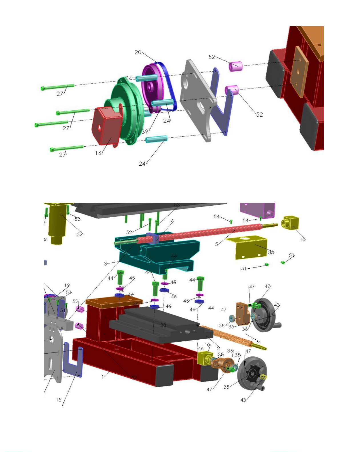
TL518 PART LIST
1 TL518 BASE
2 X/Y TABLE BASE
3 Y CARRIAGE
4 X CARRIAGE
5 X LEAD SCREW
6 Y LEAD SCREW
7 X BALL NUT HOLDER
8 Z BASE
9 Z LINEAR BEARING
10 BALL NUT
11 Z SHAFT BRACE
12 Z LINEAR SHAFT
13 Z CARRIAGE ASSEMBLY
14 Z PLATE TOP
15 PLATE MOTOR BACK
16 MOTOR COVER
17 MOTOR SERVO
18 X MOTOR COVER
19 SPROCKET LARGE
20 TIMING BELT SERVO
21 TIMING BELT SPINDLE
22 X MOTOR PLATE
23 X PLATE SPACER
24 SPACER MOTOR SERVO
25 SPACER SPINDLE
27 SCREW 8-32 X 2 1/4
28 Y MOTOR PLATE
29 SPINDLE MOTOR
BRACKET
30 JAMER PLATE
31 SPROCKET SPINDLE
32 SPINDLE ASSEMBLY*
33 SPINDLE COVER
34 SPEED CONTROLLER
35 X/Y HAND WHEEL
36 Y TABLE BEARING
37 X TABLE BEARING
38 BEARING THRUST 10MM
39 SPROCKET MOTOR
40 Z LEAD SCREW
41 SCREW 8-32 X 2 1/2
42 BEARING THRUST 5/16
43 NUT HANDWHEEL
44 SCREW ½ X 1 ¼
45 SPLIT WASHER ½
46 WASHER ½
47 SCREW M8 X 20
48 SCREW SOCKET LOW HEAD
M8 X 25
49 SCREW SOCKET M8 X 25
50 SCREW M5 X 20
51 SCREW BUTTON 10-32 X 3/8
52 SCREW 10-32 X 1.25
53 SCREW M6 X 20
54 SCREW 6-32 X 3/8

4

5

6
7

8
Unpacking
1. Release the gib and the Z-jam screw.
2. This screw is useful during manual machining operations. Do not over tighten it.
3.
4.
5. Wipe clean all the grease from the machine and oil all the moving parts.
6. Make sure that all moving parts are moving freely.
7. Make sure that the spindle timing belt is stretched enough and that the motor sprocket doesn’t
rub on the Z-plate.

9
8. Clean thoroughly ball screws. During machining protect the ball screws from the metal chip
particles. Keep them clean all the time.
9. Wipe clean all the grease from the machine and oil all the moving parts.
Installation
The machine has four threaded holes on the bottom of the base. It is recommended to install leveling legs
or 3/8”-16 screws to level the machine on sturdy surface. Alternatively it is possible to bolt the machine
base to the table surface. This method is preferable if you will be machining heavy parts and the part
weight may tilt the machine when the X-carriage is in the extreme right or left position.
The location of the threaded inserts on the bottom of the base is shown on the picture below.

10
General Safety and Warnings
• Wear appropriate safety glasses.
• Install machine on a sturdy surface and bolted to the tabletop using 3/8x16 machine screws.
• Ensure that the work piece and cutter are mounted securely before taking a cut.
• Check that work is mounted squarely.
• Mount work in a vise that is bolted or held magnetically to the table. Use proper hand tools to
make adjustments.
• Hold milling cutters with a cloth to avoid being cut when handling them.
• Move table as far as possible from cutter while setting up work to avoid injuring your hands.
• Mill the largest surface first.
• Keep hands, brushes and rags away from the revolving milling cutter.
• Use a vacuum, brush or rake to remove cuttings only after the cutters have stopped moving.
• Change cutting compounds periodically.
• Keep cutters sharpened correctly and in good condition.
• Keep working surface clear of scraps, tools and materials.
• Keep floor around the milling machine free of oil and grease.
• Use lifting equipment when appropriate to move heavy work to or from milling machines.
Before starting, make sure that:
• All guards are in place
• Work is properly secured in place
• Bolts used to hold down work clear the tooling
• Tooling and supporting pieces are properly tightened in position
• Table stops are secured properly
• Handles on all feed screws are in neutral
• Table is free of stock, tools or other loose material
• The arbor and arbor support are clear of the work
Ensure that the following factors are considered when setting cutting speed:
• Material to be machined
• Type of cutter
• Finish required
• Depth of cut
• Rigidity of machine and work piece
• Do not wear gloves, rings, watches or loose clothing. Tie back long hair.
• Do not attempt to mount, measure or adjust work until cutter is completely stopped.
• Do not use an excessively heavy cut or feed as it can cause the cutter to break. The flying pieces
could cause serious injury.
• Do not reach over or near a revolving cutter. Keep hands at least 30 cm (12 in.) from a revolving
cutter.
• Do not lean or rest hands on a moving table.
• Do not make any adjustments while the machine is running.
• Do not use paper shims to check the distance from the cutter to the stock.

11
• Do not move the operating levers without knowing what they control and what action is going to
take place.
• Do not leave machine unattended while it is running.
• Use liquid cooling when possible to prevent airborne dust especially when working with plastics
such as fiberglass or phenolics.
Specifications:
Spindle Motor 120 V, 28000 RPM
Spindle Speed 100 - 6500 RPM,
Electronic Speed Control
Spindle Rotation CW
Milling Capacity ¾ Face Mill on mild steel
Ball Screws Pitch 0.200”
Maximum X Travel 10”
Maximum Y Travel 6”
Maximum Z Travel 10”
Swing 11”
X/Y Dial Resolution 0.001”
Table Size 18 5/8” x 6”
Base Size 10 1/8” x 9 3/8”
Spindle taper MT2
Weight 170 Lb.
Shipping weights 200 Lb.

12
Printer Port and Input Connector Wiring
Printer port connector Input Connector
PIN PRINTER PORT CONNECTOR INPUT CONNECTOR PIN
1 Spindle Power
2 Step X
3 Direction X
4 Step Y
5 Direction Y
6 Step Z
7 Direction Z
8 Step A
9 Direction A
10 Input 3
11 Input 4
12 Input 7
16 Cooling Pump Power
18 Common 9
1 Is connected to +5VDC

13
Important:
LEDs can be seen through the controller cover are lit under normal operation.
If one of the axes reaches the end of motion or cannot move for any reason, all axes
will stop moving to prevent damage to the machine and motors.
The LEDs will blink indicating the need for a reset.
In order to reset the controller you have to shut it off and then turn it on again.
All previous axes position will be lost.
LED blinking CODES:
• 1 BLINK: Stuck motor. The encoder error exceeded maximum allowed
error
• 2 BLINKS: Motor Halt Command from other motor. The other motor
signaled en error causing the controller to halt all the motors.
• 3 BLINKS: Over-current.
• 4 BLINKS: Thermal overload.
If the controller stops durin
g
machinin
g
, low the feed, axis acceleration or depth
of cut.

14
Tohoko Ricoh Type 7K00011 Servo Motor Specifications
• Nominal voltage 24VDC
• No load power 55 watt
• No load speed 4600 RPM.
• Nominal torque 12 oz.in. @ 2.3 amp, 4000 RPM.
• Maximum current 10 Amp.
• Encoder resolution 400 per rev.

15

16
Fine-tuning.
Number of step per inch for each axis may change slightly according to the precise lead screw pitch for a
particular machine. It is a good practice to fine-tune each axis number of steps per inch according to a dial
indicator reading as it is shown on the picture.
Using your software move the corresponding axis by one inch and adjust if necessary the software setup
according to the actual indicator reading.
Repeat this procedure for all axes.

17
DSP Servo Controller
1. X, Y, Z, A connectors are for motors of the corresponding axis.
2. Input connector is not used for normal operation. It is intended for future add-ons, such as Home
or Limit switches.
3. Printer Port connector is connected to a computer printer port with the furnished cable.
4. Spindle receptacle on the front panel energizes by the M3 or M03 statement in the program. It
turns off with M5 or M05 statement in the program. The spindle speed controller should be
plugged into it.
5. Cooling receptacle energizes by the M8 or M08 statement in the program. It turns off with M9 or
M09 statement in the program. This receptacle is used to control a cooling pump. Don’t plug a
vacuum cleaner into this receptacle because of the current limitation.
6. 120 V Power input has a built in fuse holder. The fuse is 10amp, 5mm size.
7. The manual On-Off switch may be used during tool change. When a program calls for a tool
change it is possible to shut of the controller, change the tool and manually bring the Z-axis to the
previous position. Then turn the controller on again to continue the program.
8. When operating the mill manually, unplug motors from the controller.
9. For a safety reason turn the controller power on only after the computer program is on the
computer screen. During computer boot-up the printer port outputs are in unpredictable state and
the controller can randomly turn the spindle or cooling pump on without warning.

18
Spindle Speed Control
Periodic maintenance.
• Do not over tight gib screws on dovetail axes. Gibs are metal strips that sit on one side of a
dovetail slide, such as the cross-slide and compound, and which are adjustable to take up any slack
or slop so that the dovetail slide is very smooth. The table should move smooth by hand cranks.
All dovetails are hand lapped. However as any mechanical equipment the mill requires some
running time to make the matching parts fit. After 10-20 hours of operation it may be necessary to
adjust gib screws on all axes.
The fuse is located in the bottom portion of the power
entry on the back of the controller. Use a small
screwdriver to pull open the fuse compartment.
The fuse is 5mm size and rated 10 amps.
Spindle speed control adjustment is located on the right
side of the spindle carrier. The front switch central
p
osition turns spindle off. In VA
R
-position spindle
RPM is adjustable. In FULL-position spindle turns at
full speed regardless of the know position. The spindle
RPM scale is not calibrated. It is ratiometric to the
maximum speed.

19
After gib screws adjustment secure all jam nuts.
• Use good quality machine oil to lubricate all moving surfaces. Avoid using WD40 and such
products with additives. They may create residue build-ups.
• Use lubricating grease on all lead screws.
• Never use a drill chuck in milling operation. Use only supplied MT2 collets.
Removing Ball Screws
Do not remove ball screw from the ball nut without inserting an arbor into a ball nut to prevent loosing
balls.
Follow the procedure:
1. Attached an cardboard arbor tight to the end
of the ball screw
2. Engage and rotate both the arbor and the ball
screw.
3. Make sure that the arbor is inserted into
entire screw
4. Secure the arbor with a plastic tie.

20
When re-assemble follow the reverse procedure.
The cardboard arbor is included with the mill
X and Y Lead Screws Axial Free Play Adjustment
An excessive axial free play in the thrust bearings may be compensated as follow:
1. Hold the wheel nut with the 10mm
ranch (Pos. 2) and release the hex jam
screw with the hex driver (Pos. 3).
2. Holding wheel (Pos. 1) with your hand
tight the wheel nut with the ranch (2).
Don’t over tighten it.
3. Holding the ranch (2) tight the hex jam
screw with the driver (3).
Z-Axis Free Play Adjustment
Adjusting the nut as shown on the picture
below may compensate an excessive axial
free play in the thrust bearings on Z-axis.
You may hold the Z-Ball Screw when
doing this. Don’t over-tighten the nut!
Table of contents
Popular Power Tools manuals by other brands


AEG
AEG A18ERW38B Original instructions

NRD
NRD Sentinel 6210 Installation operation & maintenance

NetterVibration
NetterVibration NED 605 operating instructions

Ironton
Ironton 45981 owner's manual

Haussmann Xpert
Haussmann Xpert PNT108-B Operator's manual

Scheppach
Scheppach DP13 Translation from the original instruction manual


