TOX PRESSOTECHNIK FinePress PFS Series User manual
TOX®PRESSOTECHNIK GmbH & Co. KG Riedstraße 4 D-88250 Weingarten
Tel. +49 (0) 751/5007-0 Fax +49 (0) 751/52391 www.tox-de.com E-Mail: info@tox-de.com
Operating Manual
TOX®-FinePress
Pneumatic press
Type PFS /PFL /PFW

Pneumatic Press PFS /PFL /PFW
2 OM 45.PFS-PFL-PFW.201803.en

Pneumatic Press PFS /PFL /PFW
OM 45.PFS-PFL-PFW.201803.en 3
Content
Available accessories.................................................................................4
1Technical data.....................................................................................5
Overview of pneumatic press..............................................................6
2About this manual ...............................................................................7
Copyright, guarantee ..........................................................................7
Legends of figures and position numbers...........................................8
Explanation of symbols .......................................................................8
3Safety ..................................................................................................9
Safe use of the machine .....................................................................9
Organizational measures to be taken by the operating company ......9
Transport, installation and operation ................................................10
Maintenance and repair ....................................................................10
Protective guards ..............................................................................11
Environmental protection ..................................................................11
Warning and information signs .........................................................12
Information on danger points ............................................................12
4Description of the press ....................................................................13
Intended use .....................................................................................13
Conditions for use .............................................................................13
Storage conditions ............................................................................13
Press function ...................................................................................14
5Transport...........................................................................................14
Delivery of the machine ....................................................................14
Transporting the machine .................................................................15
6Installation .........................................................................................16
Erecting the press..............................................................................16
Mounting the accessories .................................................................17
Setting up the press ..........................................................................21
Commissioning the machine.............................................................24
Compressed air press force table for TOX®-FinePress type PFS /
PFL /PFW .........................................................................................24
7Operation ..........................................................................................25
Safety during operation.....................................................................25
8Inspection /maintenance...................................................................26
Inspection and maintenance intervals.........................................27
9Faults: causes and solutions.............................................................28
TOX®-Pneumatic-Presses type PFS /PFL /PFW .............................28
10 Ordering of spare parts /repair .........................................................29
Notes regarding repairs ....................................................................29
Declaration of knowledge by assigned personnel copy...............31
Pneumatic Press PFS /PFL /PFW
4 OM 45.PFS-PFL-PFW.201803.en
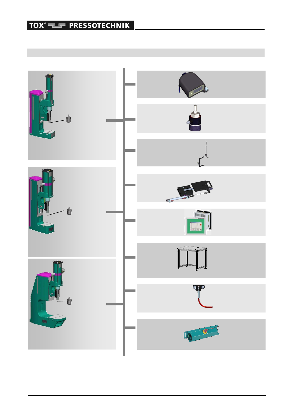
Available accessories
Press type
PFS
Pneumatic press standard
PFL
Larger open height
PFW
Larger throat depth
Accessories
Counters
ZPZ 001
Force sensor
ZAK-P04.000
(to 004)
ZAK-P16.000
(008 to 013)
ZAK-P34.000
(from 022)
Distance sensor
ZWP 080.000
Slide tables
ZHST 080.160
(manual operation)
ZHST 080.160 P
(pneumatic drive)
ZHSP 001.000
(position sensing)
Pressing monitor
Evaluation unit
EPW400
CEP
Universal base
frame
UUF 1-45
(standard with leveling
feet)
UUF 1-45 R
(+ swivel casters)
UUF 1-45 A
(+ foot rest)
TDC scanning
BDC scanning
ZOT 080.160
(manual mode)
ZUT 000
(pneumatic drive)
2-hand trigger
panel
STP 03-11
STP 03-10
+
Tool holding
fixture
+
Tool holding
fixture
+
Tool holding
fixture

Pneumatic Press PFS /PFL /PFW
OM 45.PFS-PFL-PFW.201803.en 5
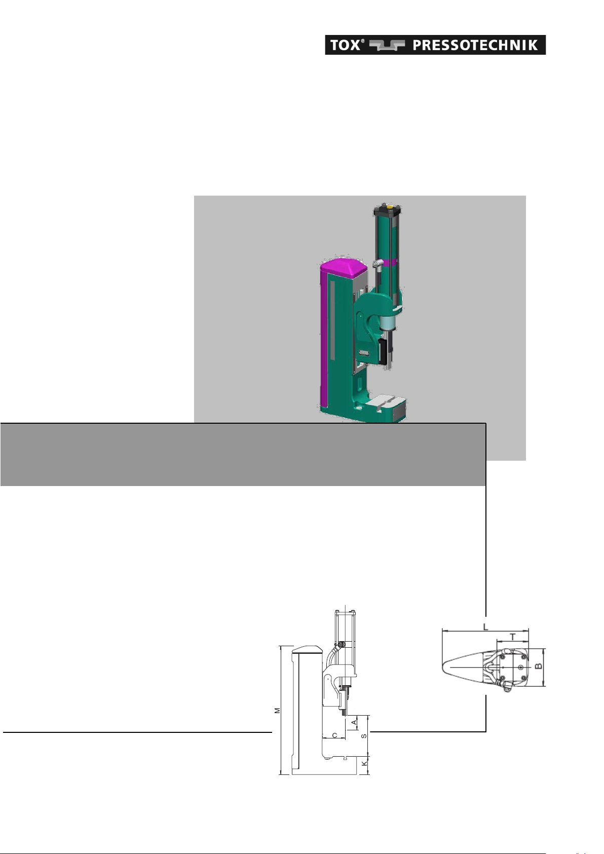
1 Technical data
PFS
Pneumatic press standard
PFL
Larger open height
PFW
Larger throat depth
Press type Force
range at 6
bar air
pressure
[kN]
Work-
ing
stroke
A
[mm]
Throat
depth
C
[mm]
adjust-
able
open
height
S
[mm]
Bed
height
K
[mm]
Overall
height
M
[mm]
Bed size
W
x
D
[mm]
Overall
depth
L
[mm]
Bed
bore
Ø [mm]
Weight
approx.
[kg]
max. de-
flection
*
[mm]
Moy
(perm.
moment
)
**
static
[Nm]
PFS 002.002
2.0 80 90 70
-
125 55 465 110x90 260 20 25 0.05 25
PFL 004.002
4.0 80 120 100
-
295
95 674 150x125 339 20 51 0.15 25
PFL 008.002
8.5 80 120 70
-
270
95 674 150x125 339 20 57 0.20 25
PFL 013.002
13.5 80 165 75
-
370
115 800 200x180 439 20 96 0.50 25
PFL 022.002
22.5 80 165 90
-
370
115 800 200x180 439 20 116 0.45 70
PFL 033.002
34.5 80 200 95
-
380
125 820 240x220 534 25 150 0.45 70
PFL 056.002
57.5 80 240 95
-
385
160 860 260x220 614 30 227 0.85 70
PFW 004.002
4.0 80 300 240
-
310
150 745 200x200 624 20 107 0.20 25
PFW 008.002
8.5 80 300 210
-
285
150 745 200x200 624 20 114 0.25 25
PFW 013.002
13.0 80 300 210
-
280
180 775 240x230 654 20 177 0.45 25
PFW 022.002
22.5 80 300 225
-
280
180 775 240x230 654 20 198 0.35 70
PFW 033.002
34.5 80 300 225
-
300
190 805 300x250 674 25 226 0.35 70
PFW 056.002
57.5 80 355 215
-
295
215 825 300x280 789 30 303 0.65 70
All dimensions in mm *Press head in topmost position **Ram in BDC
Codes of the press types
PFL 004.002 +Options e.g. + ZUT 000 Sensor for BDC sensing
Version + ZPZ 001 Stroke counter
Press force + STP 03-10 Two-hand safety control
Complete pneu-
matic press
Pneumatic Press PFS /PFL /PFW
6 OM 45.PFS-PFL-PFW.201803.en
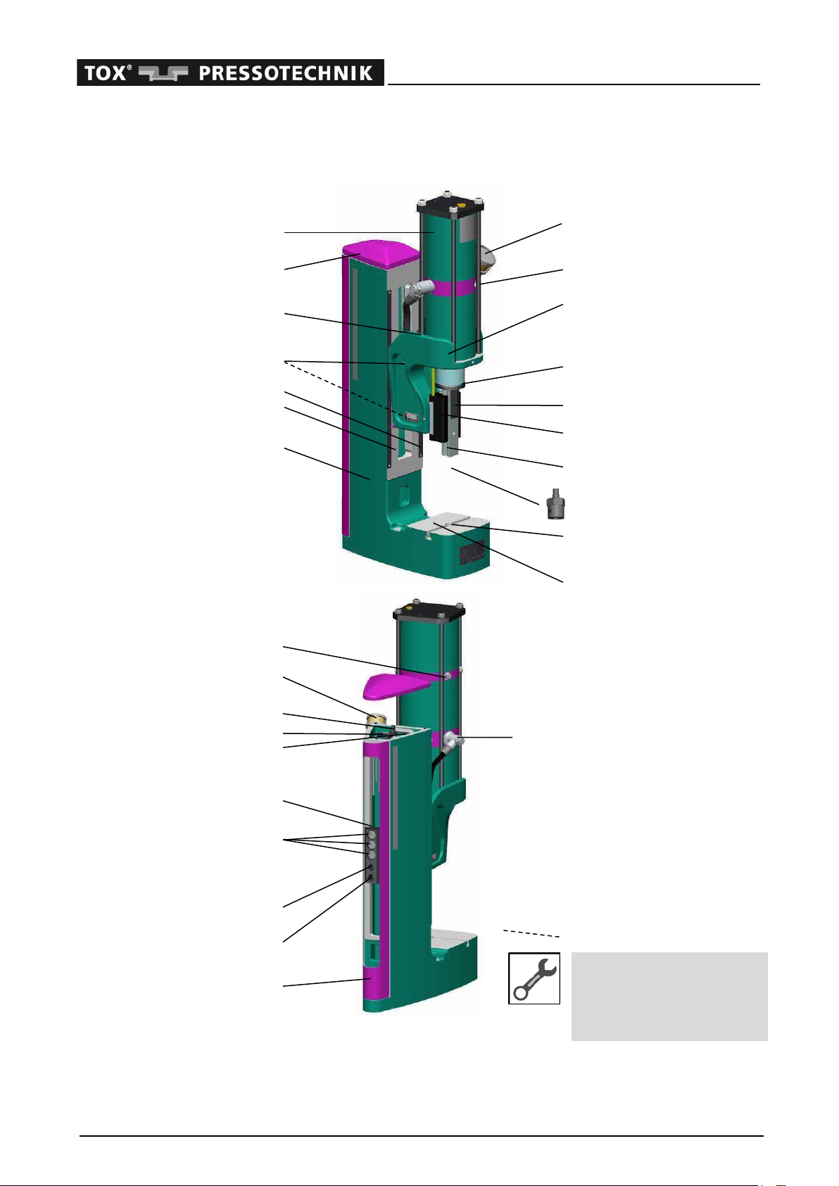
Overview of pneumatic press
Type PFL (basic device, example valid for all types)
Pneumatic cylinder
1
Frame cover
2
Threaded bores for counter
3
Threaded bore for the
1
accessory fixing device
4
Height adjustment scale, mm
5
inch
6
Press frame
7
Broken line: element is hidden
Accessories
The accessories will be
shown in the chapter 6 "As-
sembly".
Connection for counter
18
Quick-acting vent valve
19
Crank
20
Crank bolt with threaded rod
21
Hey key
22
Clamping plate
23
Fastening screws
X
Press head
24
Pneumatic connection
2
Return
stroke
25
Pneumatic connection
4
Forward
stroke
26
Rear cover of
X
press frame (slipped on)
27
17
Quick-acting vent valve,
return stroke
8
Adjustment of TDC damping
9
Press head
10
Fine adjustment of stroke
11
Stroke scale (mm/inch)
12
Guiding carriage
(ram guide)
13
Guide rail
(ram)
14
Tool holding fixture (option)
15
Groove for fastening the
13
tools or feed aids
16
Press bed
17 Screw fitting of forward stroke throt-
tle

Pneumatic Press PFS /PFL /PFW
OM 45.PFS-PFL-PFW.201803.en 7
2 About this manual
The operating manual should help you to use the
TOX®-FinePress as intended. It contains im-
portant instructions for a safe, appropriate and
economical operation of the machine. The ob-
servance of these instructions helps to avoid po-
tential hazards, to reduce repair costs and down-
time, and to increase the reliability and the ser-
vice life of the machine.
Obligatory information
for operating personnel
All persons entrusted by the op-
erating company with the
transport, mounting, operation,
maintenance and repair of the
machine must have read and un-
derstood the operating manual,
especially the chapter on safety,
before working with the machine.
Safeguarding the
operating manual
Keep the operating manual near
the machine and always make it
available to the personnel.
The "TOX®-FinePress" data sheet also includes
information on the pneumatic presses and their
accessories described in this manual. If this data
sheet is not attached to the operating manual,
you can download it from the Internet under
www.tox-en.com.
In addition to the operating manual and the man-
datory regulations regarding accident prevention
which are in force at the point of use, the recog-
nized technical rules regarding safe and profes-
sional working practices should also be ob-
served.
Appropriate use of the machine is dependent on
the intended purpose, the construction of the
production plant as a whole, the process control
system and the tool being used.
Copyright, guarantee
This operating manual and the other documents
enclosed are protected by copyright. They are en-
trusted to our customers and the users of our prod-
ucts.
Copyright:
TOX®PRESSOTECHNIK GmbH & Co. KG
This operating manual is correct at the date of
issue.
Edition: 29.03.2018
Subsequent alterations or conversions to the ma-
chine by the operator are not covered.
This operating manual is part of the delivery and
must be passed on to the new owner if the ma-
chine is resold.
We guarantee the machine in accordance with
our terms and conditions. Claims under the guar-
antee will be invalid if
−damage is caused to the machine by incorrect
operation,
−repairs or modifications are carried out by per-
sons not authorized to do so,
−accessories and spare parts are used which
are not designed to be used with this machine,
−faulty parts are not repaired immediately in or-
der to minimize the extent of the damage and
to avoid impairing the safety of the machine
(duty to repair).
Damage to the machine
Report any malfunctions as soon
as they are detected to the compe-
tent distribution partner or directly
to TOX®PRESSOTECHNIK:
TOX®PRESSOTECHNIK
Riedstraße 4
D - 88250 Weingarten, Germany
Tel. +49 (0) 751/5007-0
Fax +49 (0) 751/52391
E-mail info@tox-de.com
GmbH &
Co. KG

Pneumatic Press PFS /PFL /PFW
8 OM 45.PFS-PFL-PFW.201803.en
This machine is designed and manufactured ac-
cording to the state of the art and the applicable
German standards and specifications. The fol-
lowing norms and guidelines are met:
- Directive 2006/42/EC
- EN ISO 12100-1
- EN ISO 12100-2
We reserve the right to make technical changes.
Legends of figures and position
numbers
The figures in this part of the operating manual
are provided with a title and a figure number. Im-
portant system or equipment parts shown on the
figures are provided with component numbers.
Besides the legend and the notes, the technical
drawings also include position numbers in the
text. These position numbers are also used for
the identification of the spare parts.
Explanation of symbols
An arrow at the beginning of a paragraph in-
dicates the action steps you must complete.
This tick at the beginning of a paragraph indi-
cates a condition that must be met before be-
ginning the next step.
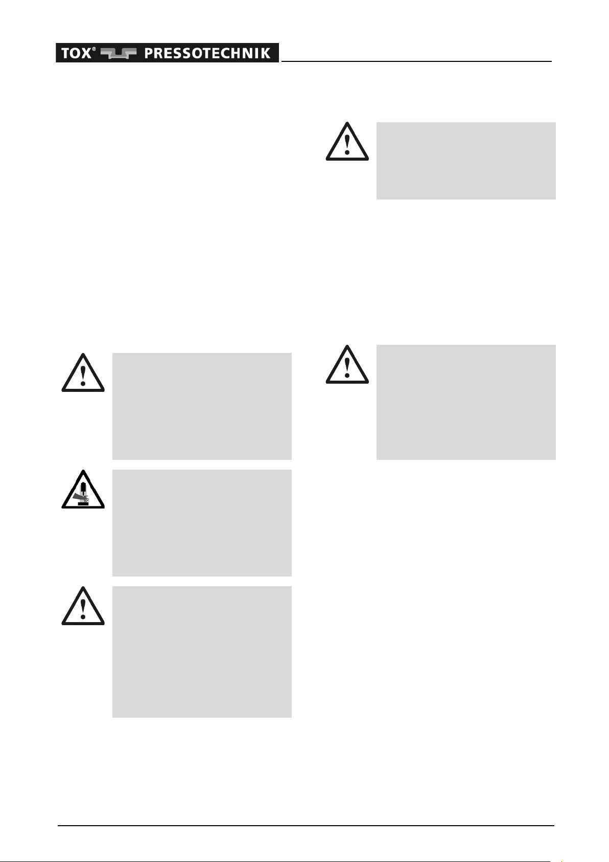
Danger notifications:
Safety
Here you will find instructions for
the prevention of damage.
These safety notes must be strictly
observed by the operating company
and user of the machine.
Danger
Warns of mechanical dangers
which can lead to personal injury
or risk to life.
Operating notes:
Note
Provides information on work se-
quences and methods that facilitate
the use of the machine.
Function
Explains the functioning of the ma-
chine or the sequence of a working
process.
Setting
Indicates important information
about setting the operating param-
eters.
Installation / Maintenance
Offers instructions regarding indi-
vidual working steps during installa-
tion or maintenance of the ma-
chine.

Pneumatic Press PFS /PFL /PFW
OM 45.PFS-PFL-PFW.201803.en 9
3 Safety
Safe use of the machine
This machine is designed and built according to
the state of the art and the applicable safety reg-
ulations. The operational safety is guaranteed.
Nevertheless, this machine poses the risk of per-
sonal injury or property damage if
•it is not used as intended,
•it is not operated by trained staff,
•it is subjected to improper conversions or modifi-
cations,
•the safety instructions are not observed.
The machine must only be operated in perfect
technical condition. All provided protective
guards must be mounted and in good working
order. The information and warning plates attached
to the machine must be observed.
Independent of the instructions given in this op-
erating manual, the current legislation on safety
and accident prevention in the respective country
apply, together with any other generally recog-
nized occupational health and safety regula-
tions.
Organizational measures to be taken
by the operating company
The operating company is responsible for ensur-
ing
•that the machine complies with the commission-
ing, operating and maintenance conditions pre-
scribed by TOX®PRESSOTECHNIK and set
down in the operating manual,
•that the machine is appropriately operated, in-
spected and serviced and that the responsi-
bilities and skills needed for the work are
clearly defined,
•that the operating staff is familiar with the
proper handling of the machine and its safety
devices as a result of suitable training,
•that damaged or removed information or
warning signs are replaced immediately,
•the protective guards provided are in place
and in good working order.
Using the machine as a plant
component
If the machine is not delivered ready
for use (see declaration of manufac-
turer), the operating company or the
appointed plant constructor is re-
sponsible for the observance of the
prescribed safety measures during
planning, assembly and completion
of the plant.
Depending on the intended applica-
tion, the mounting of further protec-
tive gears might be necessary.
We furthermore recommend that the operating
company draw up shop work instructions for the
machine, taking into account national legislation
and the qualification level of the personnel em-
ployed in each case.
Instruction and training
The operating company should ob-
tain written confirmation that per-
sonnel have attended instructional
sessions, training or seminars, to
learn about the safe operation,
maintenance and repair of the ma-
chine.
For this the operating company
may print out copies of the "Decla-
ration of knowledge of the ap-
pointed staff" template (in the an-
nex of these Instructions) and have
them filled in.
Compulsory safety inspections
Please observe the national legisla-
tion for carrying out safety inspec-
tions.
Pneumatic Press PFS /PFL /PFW
10 OM 45.PFS-PFL-PFW.201803.en
Transport, installation and operation
During transport and assembly of the machine, the
indicated part dimensions and part weights of the
machine including the tool and the accessories
must be taken into consideration.
The machine must only be mounted by author-
ized and briefed staff.
Check the machine and the accessories for dam-
age. If a machine is faulty, stop it immediately
and secure the plant against operation.
A defective machine must only be repaired by qual-
ified personnel or by TOX®PRESSOTECHNIK.
Check all supply lines for damage prior to each
commissioning. If any damage is detected, de-
pressurize the line or the pneumatic system and
have the damaged lines replaced by authorized
qualified personnel immediately.
Observe machine data
The technical data specified in the
data sheet and the settings must
be observed.
Observe the data in the operating
manual as well as the instruction
and warning plates on the machine.
Risk to individuals
During the operation of the machine
the user must make sure that neither
the user nor others are at risk due to
potentially dangerous actions.
The machine must only be oper-
ated if no one is in the danger area.
Personal protective equipment
Depending on the intended use of the
press, personal protective equipment
(PPE) might be necessary.
According to the national regula-
tions for working safety, the PPE to
be used for the intended use must
be defined in the operator's work-
ing instruction.
Maintenance and repair
Safety regulations
When performing work on the ma-
chine, please always observe appli-
cable safety regulations and legal
requirements.
Adhere to the recommended intervals for
maintenance and inspection work.
The correct repair of TOX®PRESSOTECHNIK
products requires appropriately trained qualified
personnel. The operating company or the per-
sonnel in charge of the repair must ensure that
the repair personnel are properly trained in the
repair of the product. Persons engaged in repair-
ing the machine are always responsible for their
own working safety.
Supporting equipment during
servicing or repairs
If the machine is delivered not
ready for operation or does not
have a restraint device for some
other reason, a restraint device ac-
cording to EN 13736 and EN
693:2009-11 must be provided.
Unless it is expressly stated otherwise, do not start
repair work until
•the machine is separated from the com-
pressed air supply
•the machine is switched off and protected
against restarting
•dangerous movements have come to a stop
•unauthorized, accidental or unexpected start-
ing up of the machine and initiation of danger-
ous movements due to latent energies are
prevented,

Pneumatic Press PFS /PFL /PFW
OM 45.PFS-PFL-PFW.201803.en 11
Use only original spare parts from TOX®PRES-
SOTECHNIK.
Installing the press completely
After repair or service work, any co-
vers that have been removed must
be properly assembled again.
Check also the screwing and the
tightness of all connections of
pneumatically driven accessories.
Do not modify the machine!
Arbitrary conversions or alterations
(mechanical or pneumatic) endan-
ger the safety of personnel, of the
whole machine, or of other material
assets.
Protective guards
When using the press according to its intended
use, danger to the operating staff is largely ex-
cluded. The design also takes into account any
foreseeable malfunction.
Owing to the nature of the operating cycles, how-
ever, the machine has some areas and parts
which cannot be protected without impairing its
function and operation. Therefore, in spite of
structural safety measures and mounted protec-
tive guards, there remains a residual risk
•to the life and health of the operator or of third
parties,
•damage to the tool or other material assets,
•to the efficient operation of the machine.
Pay attention to stroke length,
risk of pinching!
This fine press realizes a pneumatic
power stroke along the whole stroke
length. This extended power stroke
needs corresponding protective
measures in order to exclude any
risk of injuries.
When using the press for insert
work, a two-hand safety control
must be employed.
Protective guards
The machine may only be used if
all of the necessary protective
guards are properly installed and
are effective.
These guards must not be circum-
vented or rendered ineffective.
Safety regulations
Observe the valid national safety
regulations. Especially pay atten-
tion to the pneumatics and the
pneumatic pipes.
Particular risks
– Injuries caused by the bursting
of a pneumatic pipe.
– Crushing of limbs if
not properly handled
In the event of injuries or accidents,
consult a doctor immediately!
Environmental protection
Observe regulations
With all work on the machine, the
regulations of the country regarding
noise and environment must be ob-
served.
When selecting the required operating materials
(e.g. lubricants, lubrication oils, filter cartridges,
cleansing agents), take into consideration the
material's environmental safety, health risks and
disposal regulations in force.
Disposal
When disposing of the pneumatic
press and its accessories, observe
the local environmental protection
regulations in force at the time of
disposal. This also applies to wear
and spare parts.
Pneumatic Press PFS /PFL /PFW
12 OM 45.PFS-PFL-PFW.201803.en
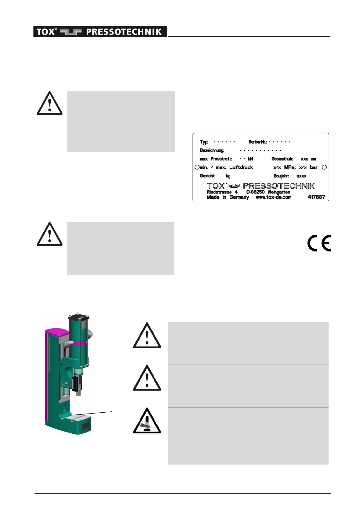
Warning and information signs
Compressed air supply:
maximum operating pressure
Observe the maximum operating
pressure
The operating pressure of max. 6
bar must not be exceeded, other-
wise the operational reliability of the
appliance cannot be longer guaran-
teed.
This sign is located on the pneumatic cylinder of
the press.
In case of compressed air mains >6 bar, a pres-
sure reducing valve must be installed upstream
to limit the operating pressure to the maximum
permitted value.
Maximum press force
Observe the maximum press
force
The specified press force must
never be exceeded or else the op-
erating safety of the machine will
no longer guaranteed.
Type plate:
In case of queries, please provide the following
details:
Type: _____________________
Serial no.: _____________________
You will find these details on the type plate,
which is located at the front of the press frame:
The code of the press types is described in chap-
ter 1 "Technical data".
If the press is delivered as a complete
machine (including tool) with a decla-
ration of conformity, it will bear the CE
marking:
Instructions for ordering wear and spare parts
are given in the "Ordering of spare parts /re-
pairs" chapter.
Information on danger points
Example: Press type
PFL, drawing without
tools. Applies accord-
ingly to all other types.
Maintenance unit, drive
Danger due to the high pressure in the pneumatic
system. Service work must only be performed by au-
thorized qualified personnel.
Observe the maximum operating pressure.
Pneumatic control (option)
Danger due to the high pressure in the pneumatic sys-
tem. Service work must only be performed by author-
ized qualified personnel.
Observe the maximum operating pressure.
Risk of shearing and crushing
Observe the safety distance to the limit of the danger
point
(1) (observe EN 349).
Exclude the risk of danger to other persons.
Assembly, service and repair work may only be exe-
cuted by authorized qualified personnel.
1

Pneumatic Press PFS /PFL /PFW
OM 45.PFS-PFL-PFW.201803.en 13
4 Description of the press
Intended use
The pneumatic presses with manual approach of
the TOX®-FinePress series can be used in com-
bination with the provided tool holding fixture and
tools for the following applications according to
the specifications of TOX®PRESSOTECHNIK:
Clinching, joining,
TOX
®
sheet-metal
joining system
Pressing,
compressing
Edging, bending,
shearing
Embossing, mark-
ing
Punching,
piercing
Riveting, crimping,
flaring
Tensioning, clamp-
ing, crimping
Stretch form-
ing, flanging
Make sure the press has enough press force for
the intended application.
The fine press must only be used for the intended
working process. Any other use or application be-
yond this does not come under the scope of in-
tended use. The manufacturer is not liable for any
damages arising as a result – the risk is borne by
the user. Permission for any application not men-
tioned here must be agreed with TOX®PRES-
SOTECHNIK.
The fine presses of the series TOX®-FinePress
are built exclusively for industrial applications.
Conditions for use
Ambient temperature
The operation of the TOX®-Press is
only permitted within
Tmin = 10°C and Tmax = 60°C.
When operated outside these tem-
perature limits, operational faults or
damage to seals may occur.
Preparation of compressed air
The machine must only be used
with filtered and dried compressed
air. The maximum permissible par-
ticle size is 40 μm.
Operation with unfiltered com-
pressed air may result in premature
damage to the seals.
The machine can also be operated
with slightly oiled compressed air.
In this case, take special care to
ensure that the oiler setting is eco-
nomical.
Special working environments
If you want to use the machine in a
special working environment (e.g.
outdoors or in a dusty or humid en-
vironment, as part of food-safe op-
eration or under particular chemical
or physical conditions), please con-
tact our service department and
ask what conditions are necessary
in order to do so.
Storage conditions
Store the press in a dry and dust-proof place.
Cover the press with a suitable dust cover. Store
the press at an ambient temperature between -
10 and 60°C.

Pneumatic Press PFS /PFL /PFW
14 OM 45.PFS-PFL-PFW.201803.en
Press function
The presses of series TOX®-FinePress type PFS
/PFL /PFW are merely pneumatically operated
and controlled. This pneumatic press of linear ef-
fect realizes a pneumatic stroke along the whole
length of the stroke. This pneumatic power
stroke needs corresponding protective
measures in order to exclude any risk of injuries.
The pneumatic cylinder is mounted directly to the
press frame.
The piston of the pneumatic cylinder generates a
power which is proportional to the pressure. The
nominal force is reached at the maximum operat-
ing pressure of 6 bar. At a proportionally decreas-
ing force, however, it is possible to operate the
presses up to approx. 3 bar.
The fine presses of this type can be used option-
ally with a purely pneumatic control system or an
electrical control system.
Due to their manifold shifting and adjusting pos-
sibilities, the machines of series TOX®-Fine-
Press can be easily adapted to the desired ap-
plications.
Technical data, machine dimen-
sions and description
The technical data can be found in
chapter 1.
Detailed information on
machine dimensions, a brief
description of the product lines
and available accessories
can be found in the "TOX®-Fine-
Press" brochure.
5 Transport
Delivery of the machine
The TOX®-FinePress is delivered ready for in-
stallation. The press does not need to be disas-
sembled for transport.
If accessories are also supplied, they must be
mounted when the press is set up. Please ob-
serve the instructions given in this operating
manual or in instructions delivered separately.
During transport, always ensure that the TOX®-
Press is appropriately handled. The means of
transport must be designed for the weight of the
press including tools and accessories.
Checking the delivery
Check that the delivery is complete and
matches the delivery note.
Check the machine for transport damage.
Report transport damage imme-
diately
Should transport damage to the
machine be found, advise us imme-
diately on the kind and extent of
damage (please state the number
of the shipping note, the machine
type and the serial number):
TOX®PRESSOTECHNIK
Riedstraße 4
D-88250 Weingarten
Tel. +49 (0) 751/5007-0
Fax +49 (0) 751/52391
E-mail info@tox-de.com
GmbH &
Co. KG

Pneumatic Press PFS /PFL /PFW
OM 45.PFS-PFL-PFW.201803.en 15
Transporting the machine
Risks during transport
The means of transport must be
designed for the press weight in-
cluding tools and accessories.
Do not pick up the machine frame
in the tool area or by the add-on
parts.
Any loose parts on the press must
be fixed and/or secured.
After each transport, check all ma-
chine parts for damage.
Risk of crushing when lowering
the press to the ground
During the transport of the machine
there is the risk of pinching when
lifting up and specially when setting
down the press.
Transport using hoisting gear or crane
A bore hole is provided for a ring bolt for lifting
the rack and pinion press. The threaded bores
(1) are located under the lid of the press frame.
Bore hole provided for ring bolt
Screw in the ring bolt at the pro-
vided position on the press frame
only. If other threaded bore holes
are used, you run the risk of dam-
aging the drive or add-on parts.
Do not fix the ring bolts to the
pneumatic cylinder!
Take off the lid of the press frame and attach
the ring bolt.
Take the crank handle and the tool out of the
press frame (they might fall out during
transport).
Attach the transport gear to the ring bolts.
Lift up the machine carefully
Pay attention to the gravity center
of the machine:
– the press might slightly swing out
when lifted up.
The transport gear may tear. There-
fore, keep a safe distance from the
means of transport.
Transport with lifting device (schematic)
Transport using a fork lift truck or pallet
truck
Safety measures
The small TOX®-FinePress is only
permitted to be transported on a
stable base (e.g. pallet) and must
be protected against sliding.
Observe the maximum load of the
means of transport.
1

Pneumatic Press PFS /PFL /PFW
16 OM 45.PFS-PFL-PFW.201803.en
6 Installation
Erecting the press
The location must be determined. The space
required for the machine must be sufficiently
dimensioned.
The required space for the supply pipes must
also be taken into consideration.
Machine weight
The location and the on-site fixture
must be calculated for the weight of
the press including the tool and the
accessories.
In addition to the weight of the de-
vice, any loads caused by the
working process must also be
taken into consideration (dynamics
and vibrations).
The working area must be defined and config-
ured in line with the applicable regulations (es-
pecially with regard to ergonomics and
safety).
The frame for the machine must be ready for
mounting.
Risks during erection
Use a suitable hoist to raise the
machine (see the "Transport" chap-
ter). The hoisting gear must be de-
signed for the machine weight.
Do not lift the machine in the tool
area or on the add-on parts.
No unauthorized individuals must
be within the danger area.
Noise protection
For noise protection, we recom-
mend placing a felt or foam mat
(approx. 1 cm) between the press
frame and the base frame and/or
the table (not obligatory).
Screwing on the press
Before operating the press, it must
be screwed to the base frame (op-
tion) or to a solid table (e.g. work
bench). Otherwise, the press is not
permitted to be operated.
Supplied tools
A set of Allen keys and the crank
for the height adjustment can be
found under the removable top
cover of the press frame.
Mounting the press
The process of erecting the press depends on
the version of the press. The mounting dimen-
sions can be found in "TOX®-FinePress" data
sheet.
Use appropriate lifting gear to place the press
on the base frame.
Align the press on the frame.
Fix the press on the provided base frame or
table.
Erecting with a base frame (option)
Mount the base frame according to the sepa-
rate mounting instructions.
Use appropriate lifting gear to place the press to
the intended position.
Align the press.
Check whether the machine is horizontal in
both axes and compensate any unevenness
using the adjustable feet (not in case of a set
of swivel casters).
Should the base frame be equipped with a set
of movable swivel casters (option), the swivel
casters must be mounted instead of the ad-
justable feet.
Set of swivel casters
Before operation, the swivel cast-
ers must be locked using the fixing
lever.

Pneumatic Press PFS /PFL /PFW
OM 45.PFS-PFL-PFW.201803.en 17
Mounting the accessories
Mounting the stroke counter
(option)
Separate the coupler (4) on the counter side
from the plug (3).
Remove the screw provided on the counter
connection (1) of the pneumatic cylinder.
Screw the pressure switch (2) in the counter
connection (1) on the pneumatic cylinder.
Mount the counter housing (5) to the provided
location on the press head using the two
cheese head screws M 5x12 (6).
Connect plug (3) with coupler (4).
Installing the sensor for TDC sensing (option)
Screw on the fixing device (6) with the two
screws M 5x10 (5) to the side of the press head.
After that, fasten the fixing device with the help
of the second screw M 5x10 to the underside of
the press head.
Plug the right-angle plug (11) in the coupling
of the magnetic field sensor (10).
Place the holding angle (2) with the magnet field
sensor (11) on the tie rod (1) of the pneumatic
cylinder. Tighten the setscrew (3) so that the
holding angle can still be moved on the tie rod
(1).
Place the straight plug (9) in the mounting clip
(7) and screw the clip with the screws (8) to
the fixing device (6) using the two highest
bores.
Shift the holding angle (2) to the required posi-
tion until a signal appears on the measuring in-
strument. When this position is reached, fix the
holding angle with set screw (3).
Make sure the magnet field sensor (10) sits
close to the pneumatic cylinder. The distance
between magnet field sensor and pneumatic
cylinder is adjusted with the help of setscrew
(4).
Connect plug (9) with the provided process
control system using an appropriate cable.
Allocation of TDC sensor:
(BMF 21K-PS-C-2-S49)
1
2
3
4
5
6
1
2
3
4
5
6
7
8
9
1
10
11

Pneumatic Press PFS /PFL /PFW
18 OM 45.PFS-PFL-PFW.201803.en
Installing the sensor for BDC sensing (option)
Screw on the fixing device (2) with the two
screws M 5x10 (1) to the side of the press head.
After that, fasten the fixing device with the help
of the second screw M 5x10 to the underside of
the press head.
Place plug (6) in the fastening clip (5), and
screw down the clip with screws (4) on the fix-
ing device (2) using the third and fourth bore-
hole seen from above.
Mount the holding plate (8) with the sensor at
the provided place on the stroke scale using
the two screws (7).
Fasten the cable with clip (3) to the side of the
press head.
Connect plug (6) with the provided process
control system using an appropriate cable.
Allocation of the BDC sensor:
(BES R04KC-POC15B-S49-00,13)
Installing the force sensor (option)
Screw on the fixing device (2) with the two
screws M 5x10 (1) to the side of the press
head. After that, fasten the fixing device with
the help of the second screw M 5x10 to the
underside of the press head.
Screw the tool holding fixture and the force
sensor (7) on the press ram o the press.
Fasten the black clamp (6) with screw M 4x8
Plug the angle plug (8) in the plug of the force
sensor (7).
For strain relief, clamp the cable into the black
clamp.
Place the straight plug (5) in the mounting clip
(4) and screw the clip with screws M 4x20 (3)
to the fixing device (2) using the two lowest
bore holes.
Connect plug (5) with the provided process
control system using an appropriate cable.
Information on force measure-
ment
is provided in the corresponding
chapters of the operating manual of
the pressing monitor, for example
EPW (accessories).
1
2
3
4
5
6
7
8
1
2
3
4
5
6
7
8

Pneumatic Press PFS /PFL /PFW
OM 45.PFS-PFL-PFW.201803.en 19
Installing the path measuring unit (option)
Extend the cylinder for the easier installation
of the path measuring unit.
Place the travel sensor (1) on the provided lo-
cation of the press head. Pay attention to a
careful threading of the rods of the path meas-
uring unit.
Fasten the connecting flange (2) of the travel
transducer to the press head with the help of
the three screws M 3x8 (3).
Position bracket (10) provided on the under-
side of the press head, on the screw bar (9)
and fasten the bracket with spanner bolt M 4.
Screw on the holding device (5) with the two
screws M 5x10 (4) to the side of the press
head. After that, fasten the fixing device with
the help of the second screw M 5x10 to the
underside of the press head.
Place plug (8) in the mounting clip (7) and
screw the clip to the fixing device (5) with
screws M 4x20 (6) using the third and fourth
bore seen from below.
Connect plug (8) with the provided process
control system using an appropriate cable.
Information on the path measur-
ing unit
is provided in the corresponding
chapters of the operating manual of
the pressing monitor, for example
EPW (accessories).
1
2
4
5
6
7
8
9
10
1
5
10
3

Pneumatic Press PFS /PFL /PFW
20 OM 45.PFS-PFL-PFW.201803.en
Mounting the sliding table (option)
Key
1
Base plate (anvil)
5
Stop (adjustable)
2
Guide
6
Handle
3
Tool plate
7
Fastening groove
4
Stop screw (not visible in
the drawing)
8
Bore hole for screw
fitting
Mount the sliding table in the bore holes (8)
using the T-groove nuts. Push the T-groove
nuts into the fastening groove (7) of the press
and tighten the fastening screws.
Align the lower tool with the tool plate (3) and
screw it down in the provided threaded bore
holes.
For fine adjustment of the insertion length, it
is possible to shift the stop (5) and to secure
it with the stop screw (4).
Slide table with pneumatic cylinder
Retrofitting
If the pneumatic cylinder (11) is
mounted to the slide table at a later
date, first fasten the angle (14) to
the provided location of the base
plate. Then lead the piston through
the opening of the angle and fasten
the cylinder with the nut. Screw
then the coupling of the piston (15)
down to the fixing device of the
slide table (16).
Duly connect the pneumatic cylinder to the
compressed air supply:
−Forward stroke (9): Extension of
cylinder
−Return stroke (13): Retraction of
cylinder
Use the throttles (9) and (13) to set the speed
for the extension or retraction of the cylinder.
For fine adjustment of the insertion length, it
is possible to shift the stop (5) and to secure
it with the stop screw (4).
Key
9
Throttle, forward
stroke
13
Throttle, return stroke
10
Connection, forward
stroke
14
Fastening angle
11
Pneumatic cylinder
15
Coupling, cylinder piston
12
Return stroke connec-
tion
16
Slide table fixing device
9 10
14 15
7
1 2 3 6
8
4
5
16
11
12
13
This manual suits for next models
15
Table of contents
Other TOX PRESSOTECHNIK Power Tools manuals

TOX PRESSOTECHNIK
TOX PRESSOTECHNIK FinePress PFHL User manual

TOX PRESSOTECHNIK
TOX PRESSOTECHNIK FinePress PFHL Series User manual

TOX PRESSOTECHNIK
TOX PRESSOTECHNIK FinePress ZFS User manual

TOX PRESSOTECHNIK
TOX PRESSOTECHNIK TOX-FinePress PFS Series User manual

TOX PRESSOTECHNIK
TOX PRESSOTECHNIK FinePress KFS User manual


