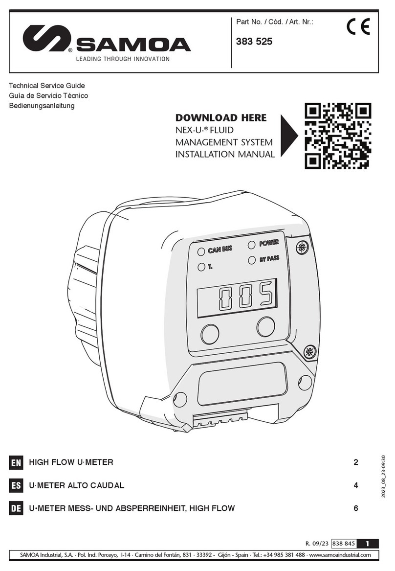
Toyo ED-3021 User manual

EXTERNAL LED INDICATOR
MODEL ED-3021
OPERATION MANUAL
kg
TOYO SOKKI CO.,LTD.
964-24 Nippa-cho Kohoku-ku, Yokohama 223-0057 Japan
TEL +81-45-540-8353
FAX +81-45-544-8354
MA4-00302-R1(2023/5)

- 2 -
MA4-00302-R1
-- Table of contents -- Page
SUMMARY ..................................................................................................... 3
APPEARANCE AND EACH PART NAME.................................................................. 3
FUNCTION .................................................................................................... 4
3-1) 16 position rotary switch to select a channel of data ........................................ 4
3-2) 4 bit DIP switch to check operation ............................................................... 4
TEST MODE ................................................................................................... 5
4-1) Select test item ......................................................................................... 5
4-2) Each test item ........................................................................................... 5
INSTALLATION AND CONNECTION ..................................................................... 6
5-1) Installation ............................................................................................... 6
5-2) Connection ............................................................................................... 6
5-3) Cable cramp ............................................................................................. 6
TROUBLESHOOTING........................................................................................ 7
6-1) Basic check point ....................................................................................... 7
6-2) Measures when indicating Error .................................................................... 7
6-3) Measures when not operated as expected ....................................................... 7
GENERAL SPECIFICATIONS............................................................................... 7
DIMENSIONAL DRAWING ................................................................................. 8
This document is translated from MA4-00188-R1 (Japanese)

- 3 -
MA4-00302-R1
Summary
This unit is an external LED indicator which receive the TOYO dedicated serial signal
transmitted from TOYO digital indicator. It has visual distance 30m or more due to its LED
character height 57mm and high intensity of LED.
The power supplied voltage is the wide range of AC85 to 264V.
Appearance and Each part name
Appearance of the unit
kg
① LED INDICATOR 5 digit LEDs, red, character height 57mm
② CABLE CRAMP x3 Dustproof, Drip-proof cover of cable
③TERMINAL Input / Output of serial signal and Power line
④ DIP and ROTARY SWITCH Select a channel and Check operation
⑤ FIXING HOLE x4 Use 4-M6 bolt screw to fix this unit
Attached accessories
1). Operation Manual 1 copy
2). Bracket (Mounted at the time of shipment) 1 set
3). Unit seal (kg, t) 2 pcs
4). Seal Pin (Inserted in one of cable cramp) 1 pc
①
②
③
④
⑤
Under a cover

- 4 -
MA4-00302-R1
FUNCTION
This unit is to indicate the serial data transmitted from TOYO digital indicator. Serial data is
delivered by current loop signal and its format conforms to TOYO dedicated one.
3-1)16 position rotary switch to select a channel of data
[0] : Corresponds to data of TOYO dedicated standard format.
Indicate the same measured value of connected digital indicator.
[1~9] : Corresponds to the header attached data of TOYO dedicated format.
Indicate the same measured value of each channel of connected digital indicator.
Switch position and indicate channel
Rotary switch position
Indicate channel
0
TOTAL
1
CH-A
2
CH-B
3
CH-C
4
CH-D
TOYO digital indicator which has multiple channel, as below, can be connected.
DLS-5026B, DLS-5031A
[A~F] : Prohibit to set [A~F] position to prevent malfunction.
3-2)4 bit DIP switch to check operation
This switch is to check whether this unit works correctly. Test items are as follows. Details
of each test item are described in the section 4.
①Display a model name and software version
② Check LEDs
③ Check a serial signal of current loop
④Check a rotary switch
※All the bit of DIP switch should be OFF when indicating data.
16 position
rotary switch
4 bit
DIP switch

- 5 -
MA4-00302-R1
Test Mode
4-1)Select test item
DIP switch bit#
4
3
2
1
Display model name and
software version
ON
OFF
OFF
OFF
Check LEDs
ON
OFF
OFF
ON
Check current loop signal
ON
OFF
ON
ON
Check rotary switch
ON
ON
ON
ON
Turn ON bit#4 of DIP switch to enter Test Mode.
Turn OFF bit#4 of DIP switch to light up all LEDs for a moment and return to indicate data.
4-2)Each test item
Display model name and
software version
Display characters as the following order
→→
is model name of this unit.
is software version 1.00.
※Version differs on the shipment date of the product.
Check LEDs
Each segment of LED is lighted up as the following
order. →→…→ →
→ Decimal point → All digit OFF
Check current loop (C/L)
signal
Connect output of C/L signal to input of it.
Before testing, connect terminal #1(OUT) to #3(IN) and
terminal #2(OUT) to #4(IN).
Display characters as follows when successful.
→→
Check rotary switch
Display the status of rotary switch and DIP switch.
If they are not correct as the setting position of the
switch, there may be malfunction of this unit.
kg
The left end of digit displays the rotary switch position
.
The other of 4digit displays DIP switch position. The
right end digit shows bit#1. [ ] = OFF, [ ]=ON
Turn OFF bit#4 to light up all LEDs for a moment and
return to indicate data.
※Caution
When there is something wrong at one of above checking, malfunction of this unit may be
considered and please request TOYO to repair.
Don’t check this unit by not according to this operation manual. It may cause malfunction.
Display rotary switch position
Display DIP switch position
bit #4 #3 #2 #1

- 6 -
MA4-00302-R1
Installation and Connection
5-1)Installation
1). Operation temperature range of this unit is −10 to +40℃.
Please install this unit in a place not exposed to direct sunlight and condensation.
2). This unit has basic dustproof and drip-proof structure, but not waterproof.
Please install this unit in a place not exposed to direct water.
3). The power supplied voltage is AC85 to 264V.
Please make twist of AC wire.
4). This unit is designed to fix by wall mount.
Please make use of holes 4-Φ7.0 of attached bracket and fix with M6 bolt screw.
5-2)Connection
First remove a drip-proof cover at underneath of this unit and wire on the terminal as
below. Terminal is 7.62mm pitch crimped terminal.
OUT : Output of current loop serial signal. No polarity.
For connecting TOYO external equipment as cascade
IN : Input of current loop serial signal. No polarity.
SHL : Shield line of current loop serial signal
E : Earth (Grounding) of AC
AC : Wide range of AC85 to 264V is supplied
Applicable crimp : Use a crimp terminal for M3 up to 6mm.
The shield line of each cable shall be grounded by either this unit or each connected
instrument, so that there is no ground loop.
Terminal #5(SHL) and #6(E) are connected inside.
5-3)Cable cramp
1). Applicable outer diameter of a cable Φ4 to 10mm
2). Structure Basic dustproof and Basic drip-proof
3). Measure of no usage of output cable Fill attached seal pin into a cramp not to leak
Terminal #1 #2 #3 #4 #5 #6 #7 #8

- 7 -
MA4-00302-R1
Troubleshooting
If this unit is malfunctioning, please contact us if the problem cannot be solved by the
following measures. At this time, please inform us of the model name, product serial
number, the malfunction symptoms and usage as much as possible.
6-1)Basic check point
1). Check whether the power supplied voltage (AC85 to 264V) is normal and stable.
2). Check whether the terminals are connected correctly and firmly.
6-2)Measures when indicating Error
is indicated when current loop signal input is stopped for 1 second or more.
Check whether a current loop signal is disconnected.
is indicated when receiving data is not correct.
Check whether other than TOYO digital indicator is connected.
6-3)Measures when not operated as expected
Check operation of this unit at Test Mode. Please refer to section 4, Test Mode.
General Specifications
1). Structure Basic dustproof and Basic drip-proof. Not water proof.
2). Supplied power voltage AC85 to 264V
3). Power consumption approx. 20VA
4). Operating temperature −10 to +40℃、 20 to 85%R.H. (no condensation)
and humidity range
5). Mounting method Wall mount
6). Mass approx. 5kg

- 8 -
MA4-00302-R1
Dimensional Drawing
t
kg
kg
Fixing hole 4-Φ7
M8 bolt screw
Attached unit seal
C/L output C/L input Power line
This manual suits for next models
1
Table of contents
Other Toyo Measuring Instrument manuals
