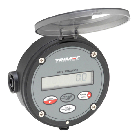
Trimec RT Series User manual

IMRT20 D- 2410
I N S T R U C T I O N M A N U A L
FLOW RATE TOTALISER
with backlighting & flow alarms
Utility Series
Declaration of Conformity
Trimec Industries Pty Ltd declares under sole responsibility that the products :
Flow rate totaliser model : RT…
to w hich this declaration relates are in conformity with the standards noted below :
EN 60529 : 1991 Degrees of protection (IP)
EN 61326 : 1998 Industrial electromagnetic immunity & emissions
2002/96/EC Waste electrical & electronic equipment (WEEE).
Issued at Taren Point 28th
January 2010. Signed for and on behalf of Trimec Industries Pty Ltd.
Wayne Fuller, Director

2
3
TABLE OF CONTENTS
1. INTRODUCTION
1.1 Description of elements 4
1.2 Specifications 5
1.3 Overview 6
1.4 LCD displays 6
2. OPERATION
2.1 Accumulative total display 7
2.2 Resettable total display 7
2.3 Rate display 7
2.4 Keypad function matrix 7
3. INSTALLATION
3.1 Remote mounting - Surface mount footprint 8
- wall / surface mount 8
- panel mount 8
- pipe mount 9
- facia protector option 9
3.2 Flowmeter connections - unpowered sensors 10
- powered sensors 11
3.3 Wiring connections - external powering 12
- remote reset 12
- wiring requirements 12
- scaled pulse output 13
4. PROGRAM PARAMETERS
4.1 PIN number program protection 14
4.2 Resetting accumulative total 14
4.3 Engineering units 14
4.4 K-factor (flow input scale factor) 14
4.6 Rate response 14
4.7 Low frequency cut-off ( ref er clause 2.4 page 5 ) 14
5. PROGRAMMING
5.1 Programming ladder chart 15
5.2 Program detail record 16
7. PANEL MOUNT DRILL TEMPLATE 18
Press & hold Program key to show
instrument software version
PROG
Software issue

4 Introduc tion
1.1 Description of elements
Introduc ti on 5
1.2 Specifications
Display : Large backli t 6 digit numeric display with LC D characters 17mm ( 0.67 ”) high, second line
of 8 digi ts x 7mm high totalising plus 5 digits of r ate indication. Program mable 0~ 3 decimal
plac es for all d ispl ay s.
Signal Input : U niv ersal pulse/ frequ ency input c ompatibl e w ith Re ed sw itch, H all effec t, N amur pr ox imity
detec to rs, v oltage, curr ent & C oil (15mV P-P min). Max. input frequency 5Khz.
Minimum input frequency for rate dis play is 0.1hz with l ow frequency cut off feature
enabled, totals hav e no minimum i nput frequency w hen low frequency cut off is set to zero.
Battery power : The unit draw s about 70ụA under battery , life ex pectancy is gen erally 3 y ears. Batte ry life
reduces w hen rate is more often display ed & there is no external pow er connec ted.. Rate
displ ay defaul ts to total displ ay 1 minute after press ing the rate key in order to cons erv e
battery pow er. (reve rse p olarity p rotected)
Battery condition is continuously monitored i nter nally , the ins trument runs on 3.6Vdc, the
battery icon illuminates when the battery output falls below 3.1Vdc, at this point the
instrument will continue to operate for a short period but the battery should be change as
soon as possible, batteries are readily av ailabl e from all major elec tronic com ponent
suppliers (s ee page 2 for details).
Ex ternal p ower : Regulated 8~24Vdc x 50mA minimum.
Memory : All program med & accumulated data is s tor ed perm anently in non-v olatile mem ory .
Pulse output : N PN transistor, scale able, 5Khz max . 100mA max imum driv e capabil ity .
Phy sical : A) IP66 / 67 alumi num alloy w ith 0.3% magnesium (6% is max imum for mine sites).
B) 3 x M 16 x 1.5 femal e conduit entri es.
C) 114mm (4. 5”) w ide x 96mm (3. 8”) high x 62mm deep (2. 5”) x 480g (1l b).
D) Temperature r ange from -20ºC to +80ºC ( -4ºF to +176ºF).
Configuri ng : PIN protec ted data entry .
K-fac tor range : ( scale fac tor ) Eg. Pulses/litre, gal lon, lb etc. Programmabl e range is 0.001~ 99,999. 999
with a floating decim al point during K-factor entry .
Engineering units : Selectable Ltr, gal, m3, kgs, lbs (total). /sec, /min, /hr or /day (rate).
Bezel
Processor
Body
Facia
Factory supplied batteri es :
P/No. 1312007
R S Components
Stock N o. 596-602
Farnell Components
Order code 206-532
Suitable ba tteries als o av ailable from :
3.6V x 2.4Ah AA
Lithium Thionyl Chloride
non - rechargeable cell
+
-

6 Introduction
1.3 Overview
The instrument will display Flow Rate, Resettable Total and an Accumulated Total in engineering units as
programmed by the user. Simple flow chart programming prompts you through the programming set up greatly
reducing the need to refer to the instruction manual. All user program data is retained if the battery is removed.
Environments
The instrument is weatherproof to IP66/67 (Nema 4X) standards, constructed in ADC12 aluminum alloy with
stainless screws & viton O-ring seals. The instrument suits harsh indoor and outdoor environments & conforms to
EMC directive 89/336/EEC Electro Magnetic Compatibility.
Features
PIN Protection, NPN scaleable pulse output,Low frequency cut-off, display priority & large backlit digital display
(backlighting enabled under external DC power only).
Installation
Specifically engineered to be direc tly mounted on a variety of flowmeters, wall or surface mounted, pipe or panel
mounted. Various mounting kits are available. The instrument can be self powered or may be powered by an
external dc supply or two wire loop powered.
1.4 LCD displays
Operation 7
2. OPERATION
2.1 Accumulative Total
Accumulative total can be reset in the program mode. The accumulative total is displayed by pressing the
ACCUM TOTAL key.
2.2 Resettable Total
The resettable total display remains visible at all times & may be reset at any time by pressing the reset button for
1~2 seconds.
2.3 Rate display The second line display toggles between Rate & Accumulative Total as the appropriate keys
are pressed. The instrument will default out of the rate mode after 1 minute when under battery power, this is to
conserve the battery as the unit draws more current when it needs to calculate rate. Under external power the
instrument will remain on Rate or Accumulative Total as they are selected.
When rate is displayed the leading three alpha characters on the left of the display “flash ” the time base for rate
eg. rate /SEC. rate /dAy. & rate /min. or rate /hr to the left of the rate digits. Decimal points float to provide good
resolution & rangeability.
The minimum input frequency for rate display is 0.25hz reducing to 0.1hz If the low frequency cut-off is set to
0.1Hz ( see clause 4.7 ).
2.4 Keypad function matrix
KEY
FUNCTION IN OPERATING MODE
FUNCTION IN PROGRAM MODE
Resets the resettable total display to
zero when pressed for 1~2 seconds.
Resets the accumulative total
display to zero.
1) Pressing the Prog. & Reset keys f or 5
seconds enters y ou into the program mode.
2) Displays model & sof tware rev ision No.
Each press steps y ou through each
lev el of the program.
Displays flow rate when pressed
Selects the digit to be set, the selected digit
will be “f lashing ” indicating that it can be
incremented.
Displays Accumulative Total
when pressed.
No function
ACCUM
TOTAL
RESET
PROGRAM
ENTER
No function
Increments the selected digit each time
that it is pressed.
RATE
Ltr
Ltr / SEC
( litres / second )
Full LCD display test feature illuminates all
display segments and script text displays for 5
seconds when entering the program mode.
Accumulative Total The 8 digit display can
be programmed for up to 3 decimal places.
Reset is only possible when in the program
mode which can be PIN protected for security.
Rate display Rate is displayed with a flashing
time base of either SEC, /min, /hr or dAy
followed by up to 5 digits of rate, these are
programmable for up to 3 “floating” decimal
places.
Time bases of units /SEC & units /dAy are
displayed to the left of the digital display whilst
units /min & /hr are to the right of the rate
digits as shown.
Resetable Total This large 6 digit display can
be programmed for up to 3 decimal places.
Ltr
gal
m3
lbs
kgs
ACCU M.
TO TAL
►
/min
/hr
Ltr
/min
gal
Backlighting The LCD backlight feature will
only work from an external dc power source in
the range of 8~24V dc.

8 Installation
3. INSTALLATION
3.1 Remote Mounting
Installation 9
3.1 Remote Mounting (continued)
* Pipe mount
RES ET
ENTE R
PROGRAM
TOTAL
ACCUM
RATE
ce
Ltr
gal
m3
lbs
kgs
ACCUM.
TOTAL
►
RATE TO TALI SER
/min
/hr
* order Pipe mount kit P/No. APM
comprising two brackets,
screws and worm drive clamps.
Optional facia protector, 3mm clear
polycarbonate plate with access port
for keys. Order P/No. 1306061.
* Horizontal
pipe mount
Surface mount footprint
use 4 x M3 screws
supplied
42.6 mm
( 1.67 ” )
Wall mount bracket
Optional, P/No. AWM )
42.6 mm
( 1.67 ” )
6.5 x 19mm
slots
96 mm ( 3.8 ” )
RES ET
ENTE R
PROGRAM
TOTAL
ACCUM
RATE
ce
Ltr
gal
m3
lbs
kgs
ACCUM.
TOTAL
►
RATE TO TALI SER
/min
/hr
Panel mount options
3 x M16 conduit entries
@ 30mm pitch
Mount using 4 x M4 nuts
& washers, tap panel or
use rear case as shown
Cut a 71mm x 83mm
(2.8 x 3.3 ”) opening in panel.
Drill 4 holes to take
M4 screws on a
68.0 x 89.6mm pitch
( 2.68” x 3.53” )
See panel mount template page 18

10 Installation
3.2 Flowmeter connections - unpowered sensors
Installation 11
3.2 Flowmeter connections - powered sensors
4. Hall effect ( 5~24Vdc open collector )
DIP SW2 (pull up) is on
Hall eff ect
Reg. Vdc
Reg.
Vdc
_
+
Vdc supply
- 0V ground
+ Signal out
6
5
4
3
2
1
7
+8~24Vdc in
Pulse output
-0V (ground)
Flow
Input
-4~20mA output
-0V (ground)
not used
+4~20mA output
Low f low alarm
8
9
10
11
12
13
14
High f low alarm
not used
3
2
1
O
N
N
Ground screen
at terminal 5
Remote reset
-0V (ground)
5. Namur ( inductive proximity switch )
NOTE : Limit supply to 8.5Vdc
through an approv ed barrier f or
intrinsically saf e NAMUR proximities
DIP SW3 (pull down) is on
NAMUR
Inductiv e Proximity
-
+
Reg. Vdc
Reg.
Vdc
_
+
6
5
4
3
2
1
7
+8~24Vdc in
Pulse output
-0V (ground)
Flow
Input
-4~20mA output
-0V (ground)
not used
+4~20mA output
Low f low alarm
8
9
10
11
12
13
14
High f low alarm
not used
3
2
1
O
N
N
Ground screen
at terminal 5
Remote reset
-0V (ground)
6. Current modulated pulse ( 4mA to 20mA pulse amplitude )
NOTE : Position a 100Ω, ¼W
Resistor across terminals 3 & 5
DIP switches off
-
+
Coil with pre-amp
current modulated
B
A
Reg.Vdc
Reg.
Vdc
_
+
6
5
4
3
2
1
7
+8~24Vdc in
Pulse output
-0V (ground)
Flow
Input
-4~20mA output
-0V (ground)
not used
+4~20mA output
Low f low alarm
8
9
10
11
12
13
14
High f low alarm
not used
3
2
1
O
N
N
Ground screen
at terminal 5
Remote reset
-0V (ground)
-4~20mA output
-0V (ground)
not used
+4~20mA output
Low f low alarm
8
9
10
11
12
13
14
High f low alarm
not used
3. Coil ( Turbine & paddle style flowmeters – minimum 15mV p-p )
wheel flow sensors
All DIP switches off (position switch 1
ON if unit is effected by line noise)
use twisted pairs
6
5
4
3
2
1
7
+8~24Vdc in
Pulse output
-0V (ground)
Flow
Input
-4~20mA output
-0V (ground)
not used
+4~20mA output
Low f low alarm
8
9
10
11
12
13
14
High f low alarm
not used
3
2
1
O
N
N
Remote reset
-0V (ground)
2. Voltage Pulse
All DIP swithes off
S
N
1.1 ~ 30 Vdc
6
5
4
3
2
1
7
+8~24Vdc in
Pulse output
-0V (ground)
-4~20mA output
-0V (ground)
not used
+4~20mA output
Low f low alarm
8
9
10
11
12
13
14
High f low alarm
not used
Ground screen at -0V (5)
+
-
Remote reset
-0V (ground)
Flow
Input
3
2
1
O
N
N
1. Reed switch
DIP switch 1 & 2 are on
6
5
4
3
2
1
7
+8~24Vdc in
Pulse output
-0V (ground)
Flow
Input
3
2
1
O
N
N
Ground screen at -0V (5)
Remote reset
-0V (ground)
Switch 2 : ON engages 1 meg Ω pull up r esister
Switch 1 : ON engages 0.01µf c apacitor to suppress reed switch bounc e
DIP swit ch functions :
Switch 3 : ON engages 820Ω pull down resister
Flow
Input
3
2
1
ON

12 Installation
3.3 Wiring connections
External DC powering –required for powe red flow senso rs, display backlighting or pulse outputs.
Remote reset
Terminals 1 & 2 cater for the connection of a remote reset switch, thisw ill reset the 6 digit resettable totaliser display but does
not effect the 8 digit Accumulativ e totaliser. The remote sw itch needs to have a momentary contact action only.
Wiring requirements : Use multi-core screened twisted pair instrument cable ( 0.25 –0.5mm2 ) for electrical connection
betw een theRT and any remote flowmeter or receiving instrument. The screen needs to be earthed to the signal ground of the
receiving instrument only to protect the transmitted signal from mutual inductiv e interference.
Instrument cablingshould not be run in a common conduit or parallelwith power and high inductiv e load carry ing cables, power
surges & power line frequencies may induce erroneous noise transients onto the signal. Run instrument cables in a separate
conduit or with other instrument cables.
Installation 13
3.3 Wiring connections (continued)
Pulse & Alarm Output (for this feature the instrument must be externally powered as per page 12 )
The scaled pulse output is in the form of an NPN (current sinking) style pulse capable of sw itching up to 100mA.
Current sinking derives its name from the fact that it “sinks current from a load”. When activ ated the current flows from the load
into the appropriate output (terminals 7, 13 & 14).
Pulse scaling is set as the number of litres / gallons etc. per output pulse Eg. 0.1 litres/pulse, 10 litres/pulse, 100 gallons/pulse.
Range is 0.1 - 9999.9 Eng.unit/pulse.
The pulse width (pulse duration) of the output pulse automatically mirrors the cyclic width of the incoming pulse, for example
5Hz input frequency would produce a scaled pulse output with a duration ≤200ms, for 100Hz input the output pulse duration
would be ≤10ms.
Driving a logic input The output voltage pulse is typically the internalvoltage of the load. The loadwould normally
hav e an internal pull up resistor on its input as shown.
Driving acoil - - - - - - - The coil load is obtained by dividing the coil voltage by coil impediance ( Ω ), is expressed in amps & is
not to exceed 0.1A. The coilvoltage is connected across & must match the RT supply voltage & the output (7,13 & 14).
CAU TION :
Av oid using low cost digital
sw itch mode power packs
8~24Vdc
regulated suppl y
_
+
+8~24Vdc in
Pulse output
-0V (ground)
Flow
Input
-4~20mA output
-0V (ground)
not used
+4~20mA output
Low f low alarm
8
9
10
11
12
13
14
High f low alarm
not used
6
5
4
3
2
1
7
Remote reset
-0V (ground)
Note : Pow ering the instrument from an ex ternal DC source will cause the
backlighting feature to turn on, if this is not desirable at all times then install a
pow er isolation switch in series with the DC power source as shown.
+8~24Vdc in
Pulse output
-0V (ground)
6
5
4
3
2
1
7
Remote reset
-0V (ground)
Remote reset sw itch
Remote reset sw itch is to have a
momentary action –normally open.
+8~24Vdc
Pulse out
-0V (ground)
Low f low alarm
High f low alarm
14
13
12
11
10
9
8
- +
6
5
4
3
2
1
7
OR
coil
_
logic
input
(load)
+

14 Programming
4. PROGRAM PARAMETERS
Note: The instrument defaults out of the program mode if no programming entries are made after 4minutes.
4.1 PIN No. Program Protection
Any user defined PIN number other than 0000 will engage the program protection feature, failure to input the
correct PIN number will deny the ability to change any of the program parameters but will allow the user to step
through and view the existing program parameters.
Only one PIN number may be set but this can be changed at any time after gaining access through PIN entry.
A second back up PIN number is installed at the factory should the programmed PIN be lost or forgotten.
( refer bottom of page 16 for the back up PIN No. )
4.2 Resetting Accumulated Total
Resetting the accumulated total can only be done in the program mode.
4.3 Engineering Units
Select from available Engineering units to right of the display (refer clause 1.4), for other engineering units set
display to show no engineering units & program a suitable K-factor.
4.4 K-factor (scale factor)
Enter K-factor at S-Fact, up to 5 whole numbers & 3 decimal numbers can be entered using the arrowed keys.
4.6 Rate response
Adjustable response (rate dampening) is available to smooth out fluctuating flow input signals in order to provide
a stable rate display. Most input signal are reasonably stable and need only a low setting value of 001 to 004. The
response number (ranged 001~999) represents the number of pulse intervals (duration between each pulse) that
the processor averages and displays the rate as calculated.
As a general rule it would be best to apply a response number which is a multiple of the number of pulses a meter
produces for each cycle of its primary measuring element, for example a rotating element may produce 4 pulses
per revolution so 004, 008, 012 or 016 would be ideal response settings whereas a turbine meters with high
resolution pulse outputs would require response settings like 050, 100, 200 or in some cases involving high
frequency pulse outputs eg. 500hz, the response number would be set to say 999.
4.7 Low frequency cut-off
The low frequency cut-off is most commonly set to 0.0Hz (disabled) other than to:
1) To display rate for input frequencies below 0.25hz, for example setting the cut-off at 0.1Hz the rate will
continue to display for input frequencies as low as 0.1Hz (one pulse every 10 seconds), such conditions often
apply to flowmeters with low frequency pulse outputs.
2) Inhibit the integration & registration of “apparent flow” which at times may be encountered on mobile
installations where the movement of the vehicle or dead heading a pulsating pump may cause spurious flow
signals which are not attributed to actual flow.
3) Inhibit the integration & registration of flow at input frequencies below what is considered the minimum
accurate flow rate of the primary flow element (flowmeter).
Caution: If the low frequency cut-off is set to any value other than 0.0Hz then the integration
of rate and total will cease at frequencies on or below the set frequency value.
Programming 15
4.8 Display priority The large digits at the top of the display can be programmed to show either flow rate or
resettable total. When flow rate is selected at the top display the rate key can be used to cycle between rat e,
reset total & accumulate total, in this mode the instrument will default from rate to reset & accumulative totals after
1 minute, external power must be applied if required to display rat e at top display continuously.
4.9.1 Flow Alarms ( The RT must be externally powered as per page 12 ) Two flow alarm FET (transistor)
outputs may be programmed for Low & High flow alarms. An optional plug in alarm board is available having dual
SPDT 5 amp electro-mechanical contacts.
4.9.2 Flow Alarm Deadband
An adjustable deadband (reset differential) provides a trip buffer zone about the set point in order to overcome
alarm “chattering” when the flow rate is fluctuating close to the alarm set point. Deadband is entered as % of each
set point value (refer to page 17 for an example).

Programming 16
5.1
Programming 17
5.2 Program detail record
Your back up 4 digit PIN number is 1820
To remember consider the model No. RT - “R” is the 18th & “T” the 20th letter of the alphabet.
Continued ov er
page
Return to top
of program
press Prog. key
to step through
program lev els
PROG
if PIN protected
* * * *
Nu Pin
rESEt
ACCUM TOTAL►XXXXXXXX
S - FAct
00000.001 ~ 99999.999
S-factor (K- factor) is the number of pulses / unit v olume
or unit mass eg: 20.465 pulses / litre, gallon, kg etc.
Ltr gal m3 Ibs kgs (none)
Eng unit
0 0.0 0.00 0.000
dEc rAtE
0 0.0 0.00 0.000
dEc Accu
0 0.0 0.00 0.000
dEc tot
Low frequency cut-off is generally set to 0.0Hz (disabled) f or
most applications other than those described at clause 2.4 .
0.0 ~ 50
cut oFF
001 ~ 999
rESPonSE
rAtE
PEr SEC, /min, /hr, dAy.
Response to change in rate (see rate damp ening 4.6)
if incorrect
PIN No. is entered
rEAdonLY
Error
Read only
ProG
AccESSED
HoLd
5 4 3 2 1
RT20
ISSUE 1.0
Pin no.
* * * *
hold Program & Reset key s f or
5 secs to access program mode
RESET
ENTER
PROGR AM
TO TAL
ACCU M
RATE
totAL rAtE
toP diSP
Assign resettable total or rate to the large LCD top display
(see display priority 4.8)
PuLSE
Out 0001.0
The scaleable pulse output is set as the number of litres,
gallons etc per output pulse, see clause 4.8.
XXXXXX
Lo - FLo
XX%
L d-b ANd
NO
XX%
H d-b ANd
XXXXXX
HI - FLo
YES No
ENd Prog
Sav es settings & exits program
YES
Return to top
of program
1) Low flow alarm (Lo-Flo) occurs when the f low
f alls below the set point, High flow alarm (Hi.Flo)
occurs when the f low goes abov e the set point.
2) Deadband (d-bANd) or Reset Differential, prov ides
a buff er zone about the alarm set point i n order to
av oid alarm output “chattering ” on & off when the
f low rate is hov ering on or about an alarm set point.
The % dead band app lies abov e the Low set point and
below the Hig h set point. Deadband is set as a
percentage of each set point.
Eg: 5% deadband at a low alarm set point of
100 L/hr will cause a low alarm when the
flow drops to 100 L/hr, the alarm will not
switch off until the flow increases abov e
105 L/hr.
Optional alarm outputs
Pencil your program details here
K =
User selected PIN No.
K-factor (scale factor)
Engineering units
Decimal for Accum. total
Decimal for Rate
Decimal for reset Total
0 0.0 0.00 0.000
0 0.0 0.00 0.000
0 0.0 0.00 0.000
Units / Sec Min Hr Day
Time base for Rate
Rate response
Hertz =
Low frequency cut-off
1 pulse =
Scaled pulse output
Set at : Deadband %
Low flow alarm
Set at : Deadband %
High flow alarm

18 Index
8. ALPHABETICAL INDEX
Panel mount template 19
PANNEL CUT OUT :
71mm high x 83mm wide
( 2.8” x 3.3” )
Tapping :
Drill & tap 4 x M4 holes where indicated.
Tapping drills : 3.4mm, 1/8” or #30 drill.
Clearance drills :
Clearance drills : 4.7mm, 3/16” or #13 drill.
89.6 mm
( 3.53” )
68.0 mm
( 2.68” )
89.6 mm
( 3.53” )
83.0 mm
( 3.3” )
71.0 mm
( 2.8” )
68.0 mm
( 2.68” )
Edge rule for panel cut out & hole positioning
P
PIN number protection
14,
16
Program detail record
16
Programming
14,
15
Pulse output
13
S
Scale factor (K-factor)
14,
Scaled pulse output
13
Specifications
15
5
R
Resettable total
7
Rate response
15
Rate display
7,
15
Remote reset input
12
Rate time base
7,
15
Resetting accumulative total
15
14,
W
Wiring of flowmeter inputs
10,
11
Wiring to external power
12
Wiring requirements
12
Wiring of pulse output
13
B
Battery
2,
5
A
Accumulative total
7
Backlighting the LCD display
6
E
Engineering units
15
External DC powering
5,
12
Operation
7
O
Overview
6
Flowmeter connections
10,
11
Flow rate
6,
15
M
Model number designation
4
Mounting options
8,
9
K
Keypad functions
7
K-factor (scale factor)
14,
15
I
Input signals
10,
11
Installation
ibit totals
8 ~
13
L
LCD displays
6
Low frequency cut-off
14,
15
F
Flow alarms
15,
17
Decimal point
Displays
D
DC power
5,
12
20
6
6
Display priority
15
Table of contents
Other Trimec Measuring Instrument manuals
Popular Measuring Instrument manuals by other brands
Ascon tecnologic
Ascon tecnologic TRH22 operating instructions

Takachiho Sangyo
Takachiho Sangyo TR-1 Operator's manual
FIAMA
FIAMA EP43NET manual
Swan Analytical Instruments
Swan Analytical Instruments AMI INSPECTOR Conductivity Operator's manual

APG
APG ACF-10 Series Operator's manual
Lisle
Lisle Digidown Blue operating instructions
