Tracker PRO Series User manual

Information specifically for:
IL-TRACKER575S/1
V1.3
This manual contains important information.
Please read before operating fixture.

2
© 2005 Techni-Lux Inc.

3
IMPORTANT INFORMATION
Save original packing and documentation for warranty, service and return issues.
Limited Warranty: This warranty covers defects or malfunctions in this equipment. This warranty lasts
for a period of one year from date of purchase. It is the owner’s responsibility to provide invoices for
proof of purchase, purchase date and dealer or distributor. If purchase date can not be provided,
warranty period will start at manufacture date. It is the sole discretion of Techni-Lux to repair or replace
parts or equipment. All shipping will be paid by purchaser. This warranty does not cover lamps, fuses,
belts, power semiconductors, relays, cleaning, standard maintenance adjustments or normal wear items
or any problem resulting from the following: improper wiring, incorrect voltage (including low or over
voltage conditions and lightning), abuse, misuse, improper maintenance or an act of God or damage
resulting from shipping. Warranty will be null and void if the product is altered, modified, misused,
damaged, or subjected to unauthorized repairs. Lamps are covered by relevant manufacturer warranty.
This warranty gives you specific legal rights, and you may also have other rights which vary from state to
state. Any liability for consequential and incidental damages is expressly disclaimed. No other warranty,
expressed or implied is made. Techni-Lux liability in all events is limited to, and shall not exceed, the
purchase price paid.
Returning equipment and Repairs: All returns must be accompanied by a Return Merchandise
Authorization (RMA) number and sent pre-paid. Contact the dealer or Techni-Lux directly to obtain an
RMA. The RMA number must be clearly listed on the shipping label. Due care must be exercised in
packing all merchandise to be returned. All repairs must be accompanied by a written explanation of the
claimed problem or error encountered. Techni-Lux is solely responsible for determining a product’s
eligibility for coverage under warranty. If returning for consideration of credit, all accessories and
documentation, original protective material and cartons must be included and the equipment, packing
and carton must be in new resalable condition. Credit for returned merchandise will be issued at the
lowest current price and is subject to a restocking fee of 20%. No returns accepted on discontinued
items. Techni-Lux is not responsible for merchandise damaged in transit and reserves the right to refuse
any return that is damaged by the carrier, not accompanied by a Return Authorization Number (RMA#) or
sent by freight collect.
Claims: All claims must be made within seven (7) days of receipt of merchandise. Any physical
damage must be reported to carrier upon receipt of merchandise.
Please record the following information for future reference:
Model Number: IL-TRACKER575S/1
Serial Number: ________________________________________
Dealer: ______________________________________________
Date of Purchase: ______________________________________
www.Techni-Lux.com
10779 Satellite Boulevard
Orlando, FL 32837
U.S.A.

4
Table of Contents
Specifications .............................................................................................................................5
Fixture Overview.......................................................................................................................5
Physical.....................................................................................................................................5
Lamp Source.............................................................................................................................5
Environmental...........................................................................................................................6
Electrical ...................................................................................................................................6
Control ......................................................................................................................................6
Optics........................................................................................................................................6
Gobo / Color Size......................................................................................................................6
Rigging......................................................................................................................................6
Unit Parts.....................................................................................................................................7
Unpacking ...................................................................................................................................8
Power...........................................................................................................................................9
Voltage Selection......................................................................................................................9
Lamp..........................................................................................................................................10
Lamp Installation.....................................................................................................................10
Lamp Alignment......................................................................................................................11
Mounting ...................................................................................................................................11
Data Link DMX-512 ...................................................................................................................12
Data Terminator......................................................................................................................12
Adapter 5-to-3 pin ...................................................................................................................12
Control Panel Menu..................................................................................................................13
Start Address............................................................................................................................13
Example..................................................................................................................................13
DMX-512 Channels ...................................................................................................................14
CH 1-4 : Pan / Tilt Movement..................................................................................................14
CH 5 : Movement Speed Pan/Tilt..........................................................................................15
CH 6 : Control Reset/Lamp...................................................................................................15
CH 7 : Focus.........................................................................................................................15
CH 8 : Color Wheel 1............................................................................................................16
CH 9 : Color Wheel 2............................................................................................................17
CH 10 : Prism..........................................................................................................................17
CH 11 : Fixed Gobo Wheel.....................................................................................................18
CH 12 : Rotating Gobo Wheel.................................................................................................18
CH 12 : Rotating Gobo Wheel.................................................................................................19
CH 13 : Gobo Rotation & Index...............................................................................................19
CH 14 : Iris..............................................................................................................................20
CH 15 : Zoom..........................................................................................................................20
CH 16 : Shutter .......................................................................................................................20
CH 17 : Dimmer ......................................................................................................................20
Photometric Charts ..................................................................................................................21
Installing Gobos........................................................................................................................22
DMX-512 Background...............................................................................................................23
Maintenance..............................................................................................................................24
Troubleshooting .......................................................................................................................25
Wiring Diagram.........................................................................................................................26
Accessory Items.......................................................................................................................27

5
Specifications
Fixture Overview
•Pan range of movement: 530 degrees
•Tilt range of movement: 280 degrees
•High resolution 16 Bit Pan/Tilt movement for accurate positioning
•Pan/Tilt motor speed
•Consistent & auto correcting Pan/Tilt positioning
•Color wheel with 9 dichroic colors plus open
•Color wheel with continuous rotation for rainbow effect
•Additional color wheel with 9 dichroic colors plus open
•Remote lamp on and off
•Remote reset
•UV black light effect
•3-facet rotating prism, variable speed in both directions
•Static effect/gobo wheel with 9 gobos plus open
•Gobo wheel with 6 rotating, indexable and interchangeable gobos plus open
•Gobo wheel with continuous rotation
•Remote selection of stepped zoom degrees: 15°, 18°, 22°
•Motorized focus
•Motorized iris
•Variable shutter for strobing effects and quick blackouts
•Motorized dimmer from 0 to 100%
•Control via DMX512 using 3 pin In/Out XLRs
•Uses 17 Channels of DMX
•Digital display for DMX addressing and fixture settings
•Ventilation via forced air
•Anti-reflective coated glass optics
•High efficiency parabolic glass reflector
•Lamp: CSR575/2SE or MSR575/2
•Luminous output: 49,000 Lux
Physical
Color Black
Width 18 in (45.7cm)
Depth 18 in (45.7cm)
Height 27 in (68.6 cm)
Weight 91 lbs (41.3 kg)
Gross Weight 103 lbs (46.7 kg)
Lamp Source
Lamp Type 575w Metal Halide Discharge
Base GX9.5
Lamps GE - CSR575/2SE or Phillips - MSR575/2
Lamp Specs 575w, 1000 Hour, 7200°K Color Temp, 49000 Lumens
Ballast Type Magnetic

6
Environmental
Maximum ambient temperature 105°F (40°C)
Maximum exterior surface temperature 176°F (80°C)
Minimum distance to flammable surface 3.3ft (1m)
Minimum distance to illuminated surface 4ft (1.2m)
Electrical
Factory Setting 120v 60Hz
Selectable Voltages 100v / 115v / 208v / 220v @ 50 or 60Hz
Rated Power 850W, 7A @ 120v
Fuses 15A Time Delay (Slow) Size: ¼” x 1¼”
Control
Protocol USITT DMX512 (1990)
Channels 17
Pan / Tilt Resolution16 bit
Data I/O 3 Pin XLR (Cannon)
Modes Master / Slave / DMX
Optics
Reflector High efficiency Dichroic coated Parabolic
Lenses Anti-reflective coated
Zoom 15°, 18°, 22° Stepped, Selectable Focus Correction
Gobo / Color Size
Gobo Outside Diameter 1.06” (26.9mm)
Image Diameter 0.91” (23mm)
Thickness Max 0.138” (3.5mm)
Rigging
Position Floor or Truss mount
Orientation Any
Mounting Points 2
Clamp Orientation 0°, 90°, 180°, 270°
Safety Point Eye Bolt

7
Unit Parts
Front panel:
10 - Mode-button
11 - Enter-button
12 - Up-button
13- Down-button
14
- Display
Rear panel:
5 -Power switch
6 -DMX output
7- DMX input
8- Power cord
9- Fuse holder
1- Moving head
2- Yoke
3- Carry handles
4 - B a s e

8
Unpacking
Immediately upon receipt, carefully unpack and inspect the fixture to verify that all parts are
present and have been received in good condition. If any parts appear damaged from shipping
or the shipping carton shows signs of mishandling, retain all packing material for inspection and
notify the shipper immediately. Save all original packing and carton. In the event that the
merchandise is to be returned, the original carton and packing must be used. The customer will
be billed for a new carton and packing if merchandise is received without the original carton and
packing. The plastic bag shipped with the fixture can be used to keep the fixture clean if stored
or installed in a temporarily dusty environment. Do not operate fixture with plastic bag in place.
Save Shipping Materials
The packing and carton are designed to provide the fixture with protection during
shipping. Save original packing and documentation for warranty, service and return
issues. Additional charges will be applied to return items not received in original or
incomplete packing.
Claims
Physical damage must be reported to the Freight Carrier or Shipping Company upon
receipt of merchandise. Damage incurred in shipping is the responsibility of the Freight
Carrier or Shipping Company. It is the customer's obligation in the event that
merchandise is received damaged caused by shipping to notify the Freight Carrier or
Shipping Company immediately. All other claims not related to damage incurred during
shipping must be made to the Dealer or Distributor within 7 (seven) days of receiving
merchandise.
Returns
Returned merchandise must be sent prepaid, in the original packing with a Return
Merchandise Authorization number (RMA) clearly listed on the shipping label. Items
sent by Freight Collect or without a RMA number will be refused. Call your sales person
and request a RMA prior to shipping. Be prepared to provide the model number, serial
number and a brief description of the nature of the return. Shipping damage resulting
from inadequate packaging is the customer’s responsibility. Customer will be charged
additional shipping charges to return products received in non original packing and or
cartons.

9
Power
Do not apply power to the fixture until input voltage setting and power source are verified.
For protection against electric shock, fixture must be connected to suitable earth ground.
Make sure fixture is cool and disconnected from power mains before any service.
The listed current rating is its average current draw under normal conditions. All fixtures must be
powered directly from a switched circuit. This fixture cannot be run on a rheostat or dimmer
circuit even if used solely for a 0% to 100% switching. Before applying power to a fixture, check
that the fixture’s input voltage matches the power source voltage. Consult a qualified electrician
if there are any concerns about proper connection to power.
Pin
Cable (EU) International
Brown
Light blue
ellow/Green
Y
Black
White
Green
Live
Neutral
Earth
L
N
Cable (US)
Voltage Selection
Make sure fixture is cool and disconnected from power mains before any service.
This fixture ships from the factory set for 115v 60Hz operation unless otherwise specified
or marked. Before accessing the Transformer Connection, make sure fixture is cool and
physically disconnected from power mains. Remove the metal cover that extends
across the base from the Power Input to the Display. It is held by 9 Phillips screws. Two
connections must be moved to adjust input voltage and one must be moved to adjust
Line Frequency.
Transformer Ballast
10
Lamp
Make sure fixture is cool and disconnected from power mains before any service.
Do not touch the lamp glass with bare fingers. Wear eye protection when handling lamp.
When operating, always allow the lamp to cool at least 5 minutes before attempting to re-strike
the lamp. Not doing so can cause damage to the fixture and lamp. This fixture uses a 575w
Metal Halide Discharge lamp. Either a CSR575/2SE from GE or a MSR575/2 from Phillips can
be fitted. Both lamps have an average rated life of 1000 hours. The lamp manufacturer
determines the rated lamp life under specific test conditions. Factors such as the number of
strikes, lamp orientation, line voltage and lamp temperature all affect the actual number of hours a
lamp will operate. Lamp temperature is the most controllable and with routine cleaning and
maintenance, can be kept in the optimal range to allow the maximum possible life. As Discharge
lamps age, the glass envelope becomes weaker increasing the chance of failure due to the high
internal pressures. Rupture could result in damage to the fixture and/or injure people nearby.
Lamp manufacturers state operating a lamp beyond its rated number of hours constitutes a
considerable risk for lamp rupture. Lamp manufacturers recommend lamps be replaced once the
rated life of a lamp has been reached.
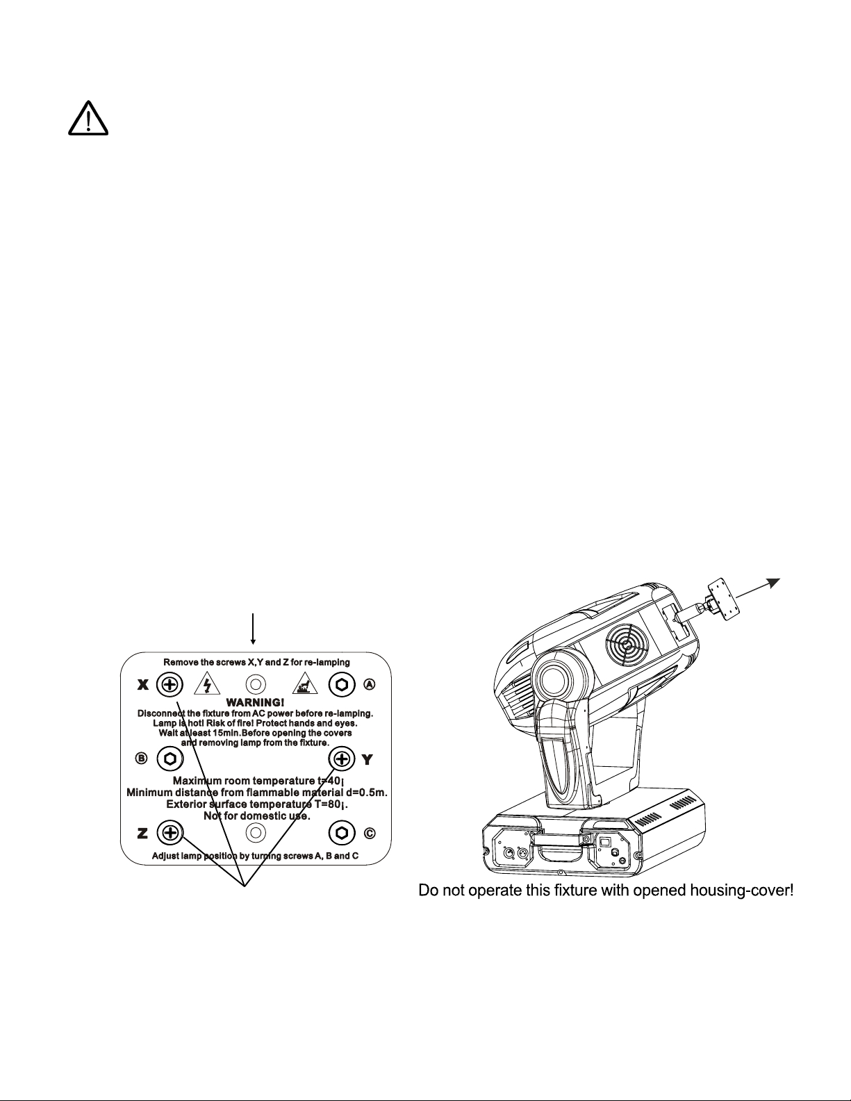
Lamp Installation
1. Physically disconnect fixture from power mains.
2. Locate the Lamp Cover. Do not proceed until the Lamp Cover is cool to touch.
3. Remove the 3 fastening screws labeled X, Y and Z.
4. Carefully draw out Lamp Cover and lamp. Remove old lamp (if installed). Never
handle lamps with bare hands. Dispose of lamp properly.
3
p
hilli
p
s screws "X,Y,Z"
L
amp cover
5. Insert new lamp into socket. Ensure lamp is properly seated.
6. Carefully replace Lamp Cover and lamp. Ensure that lamp wires are not pinched or in
contact with the lamp when the Lamp Cover is fully installed.
7. Replace the 3 fastening screws labeled X, Y and Z.

11
Lamp Alignment
Due to slight variations between lamps it may be necessary to perform fine adjustments
to remove excessively dark or bright spots in the output field. The lamp holder is aligned
at the factory, large adjustments to the alignment will not be necessary. Excessively
bright spots can damage optical components.
1. Apply power to the fixture.
2. Using a controller, strike the lamp with
shutter and dimmer to 100% and project an
open white beam on a flat neutral colored
surface.
3. Center the bright spot of the beam using
the Adjustment Screws A, B and C.
4. After centering the bright spot of the beam,
turn each Adjustment screw ¼ turn either
all clock wise or all counter clock wise until
the projected beam is as evenly bright as
possible.
Mounting
Always consult a qualified professional when rigging. This fixture may be placed on any flat
surface or truss that is capable of safely supporting the weight. When selecting a mounting
position, take into consideration access for routine maintenance. This fixture may be mounted in
any position provided there is adequate room for movement and ventilation. Mount the fixture
securely using two mounting clamps and a safety cable. An Eye Bolt is provided for safety
attachment. Safety cables must always be attached to the fixture. Do not use handles as
secondary mounting points. Do not mount in a place where the fixture will be exposed to rain,
high humidity, extreme temperature changes or restricted ventilation. Do not obstruct the vents
or fans. Keep fixture a minimum of 3.3ft (1m) from flammable materials.
3 ad
j
ustment screws "A,B,C"

12
Data Link DMX-512
For data, this fixture uses 3 pin XLR (Cannon) type connectors and shielded twisted pair cable
approved for EIA-422/EIA485 use. Fixtures are connected in Daisy Chain topography with only
one data source and no branching is allowed. Systems using 5 pin DMX interfaces can be
accommodated by purchasing 3-to-5 pin adapters or building adapter cables.
Data Terminator
A Data Terminator can be connected to the DATA OUT connection
of the last fixture to reduce the effects of noise in the signal; it is not
required for all installations. To make a Data Terminator, connect a
120-ohm ¼ watt resistor across pin 2, Data Negative (S-) and pin 3,
Data positive (S+). A qualified technician can determine if a Data
Terminator is needed.
Adapter5-to-3 pin
Numbers designating each pin can be found on connectors. Converting between the two
XLR types is done in a pin-to-pin fashion. Connect the shields to pin 1, then connect pin
2 to pin 2 and pin 3 to pin 3. This is true for converting either 5 to 3 pin or 3 to 5 pin
regardless of either connector’s gender. Pins 4 and 5 are not used on the 5 pin XLR
connectors.
5PinXLR(Plug)
Pin 1: GND(Sheild)
Pin 2: Signal(-)
Pin 3: Signal(+)
Pin 4: N/C
Pin 5: N/C
3 XLR (S )
Pin 1: GND(Sheild)
Pin 2: Signal(-)
Pin 3: Signal(+)
Pin ocket
5 Pin XLR (Socket)
Pin 1: GND(Sheild)
Pin 2: Signal(-)
Pin 3: Signal(+)
Pin 4: N/C
Pin 5: N/C
3 XLR (Plug)
Pin 1: GND(Sheild)
Pin 2: Signal(-)
Pin 3: Signal(+)
Pin
DMX
-
IN
1
2
3
- Ground
- Signal (-)
- Signal (+)
XLR Connector - Plug:
DMX-
O
U
T
1
2
3
- Ground
- Signal (-)
- Signal (+)
X
LR Connector - Socket:
DMX512
120
Ω

13
Control Panel Menu
Use the fixture’s Control Panel to access the Control Menu. The MODE Key moves between
options, UP/DOWN selects
the Action of the option and
ENTER confirms the
selection. Settings are stored
and recalled on subsequent
power cycles.
Start Address
The Start Address of a fixture is set using the “Addr” mode in the Control Panel Menu. Consult
the manual of the system’s DMX512 controller to select a desirable addressing scheme before
addressing fixtures. Each fixture connected to the DMX-512 data link requires a Start Address
to indicate the first DMX channel containing data designated for that fixture, see DMX-512
Background. Valid Start Addresses range from 1 to 512. Fixtures requiring more than one
channel for control will read subsequent channels up to the total number of channels required.
A fixture requiring five (5) channels of DMX, set to a Start Address of eleven (11), would read
data from channels: 11 and 12, 13, 14, 15. The next logical Start Address would be channel
16. Because all fixtures see the same data, fixtures may be set to any address without concern
to order in the DMX-512 chain or physical location. Choose a Start Address so the channels
used do not overlap with other fixtures. In some cases, it may be desirable to set two or more
same type fixtures to the same Start Address. In this case, the fixtures will be slaved together
and respond to the same data.
Example Select Start Addresses for 4 fixtures each requiring 17 channels of DMX.
Since these are the first fixtures added to the system, the first unit will be set to Start
Address=1. This fixture occupies DMX channels 1 thru 17. The next DMX channel
available for a Start Address is found by adding the previous fixture’s Start Address to its
channel requirement: 1+17=18. DMX channel 18 is the next available Start Address. In
this example, to maximize channel usage no empty channels are left between fixtures so
the second Start Address is set to DMX channel 18. The second fixture occupies DMX
channels 18 thru 34. Repeat the process for the remaining two fixtures: 18+17=35 and
35+17=52. Therefore, the four 17 channel fixtures have Start Addresses of 1, 18, 35 and
52. Repeat the technique once more for the first free channel in the system, 52+17=69.
Channels 69 thru 512 are available for expansion of the system.
Mode Function Action
No = Not Inverted
Yes = Inverted
DMX Start Address
Fixture Reset
Color Wheel 2 Movement Mode
No = Not Inverted
Yes = Inverted
Selectable 1 to 512
No = Default
Yes = Initiate Reset
No = Stepped Change
Yes = Linear Change
Color Wheel 1 Movement Mode
No = Stepped Change
Yes = Linear Change
Gobo Wheel Movement Mode No = Stepped Change
Yes = Linear Change
Lamp ON/OFF On = Lamp on
Off = Lamp off
Working mode = DMX-512 mode
= Automatic Demo

14
DMX-512 Channels
The Tracker 575 Spot requires 17 channels of DMX.
Channel Function
1 Pan Coarse Movement
2 Pan Fine Movement
3 Tilt Coarse Movement
4 Tilt Fine Movement
5 Movement Speed Pan/Tilt
6 Control Reset/Lamp
7 Focus
8 Color Wheel 1
9 Color Wheel 2
10 Prism
11 Fixed Gobo Wheel
12 Rotating Gobo Wheel
13 Gobo Rotation & Index
14 Iris
15 Zoom
16 Shutter
17 Dimmer
CH 1-4 : Pan / Tilt Movement
The Pan and Tilt motors use a position feedback system. If the position of either is
disturbed, the fixture will correct automatically. The Pan and Tilt Menu Modes can be
used to alter the default direction of movement. Movement speed is either automatically
determined by the fixture or manually set using Channel 5 Pan/Tilt Movement Speed.
Pan range is 530° of movement. Tilt range is 280° of movement.
CH 1 – Pan Coarse Movement (530°)
CH 2 – Pan Fine Movement
CH 3 – Tilt Coarse Movement (280°)
CH 4 – Tilt Fine Movement
DMX Value Function
0 – 255 Movement - Minimum to Maximum

15
CH 5 : Movement Speed Pan/Tilt
When set to zero (0) the fixture automatically determines the Pan/Tilt speed. Other
values are used to set the movement speed manually.
CH 5 – Movement Speed Pan/Tilt
DMX Value Function
0 Auto Speed
1-255 Fixed Speed - Fast to Slow
CH 6 : Control Reset/Lamp
Fixture reset and Lamp On/Off control is accessed from a single channel. The “No
Function” values provide buffer zones between functions and are not values to which the
channel should be set. In the case of noisy faders or unintentional movement, the buffers
will prevent slight variations in value to toggle Lamp states or start a fixture Reset.
CH 6 – Control Reset/Lamp
DMX Value Function
0-127 No Function
128-139 RESET then Lamp ON (3 second delay)
140-229 No Function
230-239 Lamp OFF (3 second delay)
240-255 No Function
CH 7 : Focus
Adjusts the focus of the projected image. When using both Gobo wheels, varying the
Focus can create many interesting effects.
CH 7 – Focus
DMX Value Function
0-255 Focus – Near to Far

16
CH 8 : Color Wheel 1
Color Wheel 1 holds 9 solid colors. Bi-Color and Color Scroll effects can also be set and
used in conjunction with Color Wheel 2 to create many color combinations.
CH 8 – Color Wheel 1
DMX Value Function
0-9 Open
10-19 Open/Red
20-29 Red
30-39 Red/Yellow
40-49 Yellow
50-59 Yellow/Magenta
60-69 Magenta
70-79 Magenta/Green
80-89 Green
90-99 Green/Orange
100-109 Orange
110-119 Orange/Blue
120-129 Blue
130-139 Blue/Pink
140-149 Pink
150-159 Pink/UV-Blacklight
160-169 UV-Blacklight
170-179 UV-Blacklight/Deep Orange
180-189 Deep Orange
190-199 Deep Orange/Open
200-255 Rainbow Color Scroll – Slow to Fast

17
CH 9 : Color Wheel 2
Color Wheel 2 holds 7 solid colors plus CTO and CTB color shifts. Bi-Color effects can
be set and used in conjunction with Color Wheel 1 to create many color combinations.
CH 9 – Color Wheel 2
DMX Value Function
0-12 Open
13-25 Open / Lt. Red
26-38 Lt. Red
39-51 Lt. Red / Lt. Yellow
52-64 Lt. Yellow
65-77 Lt. Yellow / Lt. Purple
78-90 Lt. Purple
91-103 Lt. Purple / Lt. Green
104-116 Lt. Green
117-129 Lt. Green / Lt. Orange
130-142 Lt. Orange
143-155 Lt. Orange / Blue
156-168 Blue
169-181 Blue / Lt. Blue
182-194 Lt. Blue
195-207 Lt. Blue / CTO (3200°K)
208-220 CTO (3200°K)
221-233 CTO (3200°K) / CTB (6000°K)
234-246 CTB (6000°K)
247-255 CTB (6000°K) / Open
CH 10 : Prism
The Prism effect uses a 3 facet prism to create multiple beams. The effect can be
rotated in either direction at variable speeds.
CH 10 – Prism
DMX Value Function
0-4 Open
5-127 Prism w/ Rotation – CW, Slow to Fast
128-132 Prism w/o Rotation
133-255 Prism w/ Rotation – CCW, Slow to Fast

18
CH 11 : Fixed Gobo Wheel
The Fixed Gobo Wheel contains 9 fixed gobos. In addition to the variable Vibrate and
Gobo Scroll modes, using both Gobo wheels and varying the Focus can create many
interesting effects.
CH 11 – Fixed Gobo Wheel
DMX Value Function
0-9 Open
10-19 Fixed Gobo 1
20-29 Fixed Gobo 2
30-39 Fixed Gobo 3
40-49 Fixed Gobo 4
50-59 Fixed Gobo 5
60-69 Fixed Gobo 6
70-79 Fixed Gobo 7
80-89 Fixed Gobo 8
90-99 Fixed Gobo 9
100-111 Fixed Gobo 1 Vibrate - Slow to Fast
112-123 Fixed Gobo 2 Vibrate - Slow to Fast
124-135 Fixed Gobo 3 Vibrate - Slow to Fast
136-147 Fixed Gobo 4 Vibrate - Slow to Fast
148-159 Fixed Gobo 5 Vibrate - Slow to Fast
160-171 Fixed Gobo 6 Vibrate - Slow to Fast
172-183 Fixed Gobo 7 Vibrate - Slow to Fast
184-195 Fixed Gobo 8 Vibrate - Slow to Fast
196-207 Fixed Gobo 9 Vibrate - Slow to Fast
208-255 Fixed Gobo Scroll - Slow to Fast
0
1
2
3
4
5
6
7
8
9

19
CH 12 : Rotating Gobo Wheel
The Rotating Gobo Wheel contains 6 replaceable gobos, 3 metal and 3 glass. The Gobo
Rotation & Index channel controls the position and rotation of the gobos. Using both
Gobo wheels and varying the Focus can create many interesting effects.
CH 12 – Rotating Gobo Wheel
DMX Value Function
0-36 Open
37-73 Rotating Gobo 1 (Metal)
74-110 Rotating Gobo 2 (Metal)
111-147 Rotating Gobo 3 (Metal)
148-184 Rotating Gobo 4 (Glass – Blue Field Random Dots)
185-221 Rotating Gobo 5 (Glass – Fire Texture Dichroic)
222-255 Rotating Gobo 6 (Glass – Clear Texture)
CH 13 : Gobo Rotation & Index
Rotating gobos can be rotated in either direction or indexed to a fixed orientation.
CH 13 – Gobo Rotation & Index
DMX Value Function
0-40 Indexed – 0 to 540°
41-158 Rotation – Slow to Fast
159-255 Rotation Reverse – Slow to Fast
0
6
5
4
3
2
1

20
CH 14 : Iris
The Iris allows the diameter of the beam to be reduced.
CH 14 – Iris
DMX Value Function
0-255 Beam aperture – Large to Narrow
CH 15 : Zoom
The three step zoom feature of this fixture has two modes. The Focus Correction mode
will make adjustments to help keep the image in focus when changing beam angles. The
No Focus Correction mode will not adjust the focus when changing beam angles.
CH 15 – Zoom
DMX Value Function
0-32 15° Beam Angle – No Focus Correction
33-65 18° Beam Angle – No Focus Correction
66-98 22° Beam Angle – No Focus Correction
99-127 No Effect
128-170 15° Beam Angle – Focus Correction
171-213 18° Beam Angle – Focus Correction
214-255 22° Beam Angle – Focus Correction
CH 16 : Shutter
The Shutter functions in three modes. Standard Strobe Effect where the shutter
Opens/Closes at a fixed rate. Pulse Strobe Effect where the Open and Close speeds are
different. Random Strobe Effect runs the shutter at irregular intervals.
CH 16 – Shutter
DMX Value Function
0-31 Closed (Black Out)
32-63 Open
64-95 Strobe Effect - Slow to Fast
96-131 Pause in current position
132-159 Pulse Strobe Effect - Slow to Fast
160-191 Pause in current position
192-223 Random Strobe Effect
224-255 Open
CH 17 : Dimmer
The dimmer is used to vary the intensity of the beam from full open to dark.
CH 17 – Dimmer
DMX Value Function
0-255 Intensity - Dark to Full Open
This manual suits for next models
2
Table of contents


