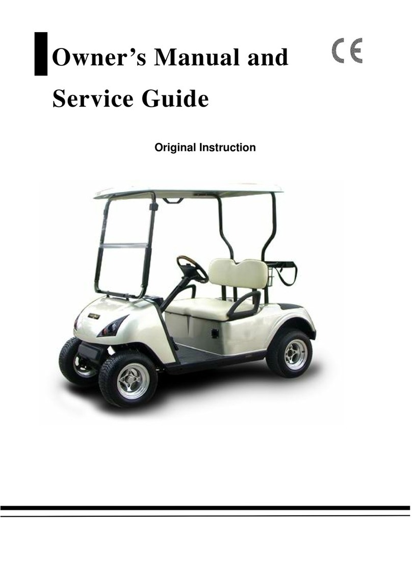
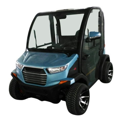
Tracker LS2 2020 User manual

REPAIR AND SERVICE MANUAL
699322- A
Issued May 2019
653635-B

SAFETY
For any questions on material contained in this manual, contact an authorized representative for clarification.
Read and understand all labels located on the vehicle. Always replace any damaged or missing labels.
The following symbols appear throughout this manual and on your vehicle. Your safety is involved when these symbols
are used. Become familiar with their meanings before reading the manual.
DANGER indicates a hazardous situation that, if not avoided, will result in death or serious injury.
WARNING indicates a hazardous situation, if not avoided, could result in death or serious injury.
CAUTION indicates a hazardous situation that, if not avoided, could result in minor or moderate injury.
Failure to comply with the warnings in this manual can result in severe injury or death.
Read this entire manual carefully before operating this vehicle. Do not attempt to operate this vehicle
until you have thorough knowledge of the controls and features.
Regular inspections and maintenance, along with good operating techniques, will help ensure your safe
enjoyment of the capabilities and reliability of this vehicle.
MANUFACTURER’S INTENDED USE
This vehicle is designed and manufactured in the United States of America (USA). The standards and specifications
listed in the following text originate in the USA unless otherwise indicated.
EXHAUST EMISSION
The exhaust emissions of this vehicle’s engine complies with regulations set forth by the Environmental Protection
Agency (EPA) of the United States of America (USA) at time of manufacture. Significant fines could result from modifi-
cations or tampering with the engine, fuel ignition or air intake systems.
BATTERY PROLONGED STORAGE
Batteries discharge over time. The rate of discharge changes according to the ambient temperature, the age and con-
dition of the batteries.
Completely charged batteries will not freeze in winter temperatures unless the temperature is less than -75°F (- 60°C).
BATTERY DISPOSAL
Lead-acid batteries are recyclable. Return discarded batteries to distributor, manufacturer or lead smelter for recycling.
For neutralized spills, put residue in acid-resistant containers with absorbent material such as sand. Dispose in accor-
dance with local, state and federal regulations for acid and lead compounds. Contact local or state environmental
authorized people for the disposal information.
(NOTICE, CAUTION AND WARNING CONTINUED ON INSIDE OF BACK COVER)

Page i
Repair and Service Manual
699322
SERVICE AND REPAIR MANUAL
GASOLINE POWERED GOLF CAR
TRACKER LS2
Starting Model Year 2020
Never modify the vehicle in any way that will alter the weight distribution of the vehicle, decrease its stability or increase the speed
beyond the factory specifications. Such modifications can cause serious personal injury or death. The manufacturer prohibits and
disclaims responsibility for any such modifications or any other alteration which would adversely affect the safety of the vehicle.
The manufacturer reserves the right to incorporate engineering and design changes to products in this manual, without obligation to
include these changes on units sold previously.
The information contained in this manual may be revised periodically by the manufacturer, and therefore is subject to change without
notice.
THE MANUFACTURER DISCLAIMS LIABILITY FOR ERRORS IN THIS MANUAL, and SPECIFICALLY DISCLAIMS LIABILITY FOR INCI-
DENTAL AND CONSEQUENTIAL DAMAGES resulting from the use of the information and materials in this Manual.
These are the original instructions as defined by 2006/42/EC.
MANUFACTURER INFORMATION:
Textron Specialized Vehicles, Inc.
1451 Marvin Griffin Road
Augusta, Georgia, USA 30906-3852
Dealer: 800-296-4804
Consumer: 877-394-6727
www.trackeroffroad.com

Page ii Repair and Service Manual 699322
This vehicle has been designed and manufactured in the United States of America (USA) as
a ‘World Vehicle’. The Standards and Specifications listed in the following text originate in
the USA unless otherwise indicated.
The use of non Original Equipment Manufacturer (OEM) approved parts may void the
warranty.
Tampering with or adjusting the governor to permit vehicle to operate at above factory
specifications will void the vehicle warranty.
When servicing engines, all adjustments and replacement components must be per original
vehicle specifications in order to maintain the United States of America Federal and State
emission certification applicable at the time of manufacture.
BATTERY PROLONGED STORAGE
All batteries will self discharge over time. The rate of self discharge varies depending on the
ambient temperature and the age and condition of the batteries.
A fully charged battery will not freeze in winter temperatures unless the temperature falls
below -75° F (-60° C).

SAFETY INFORMATION
Read all of SAFETY and this section before attempting any procedure. Pay particular attention to Notices, Cautions, Warnings and Dangers.
iii
Repair and Service Manual
699322
SAFETY INFORMATION
This manual has been designed to assist in maintaining the vehicle in accordance with procedures developed by the
manufacturer. Adherence to these procedures and troubleshooting tips will ensure the best possible service from the
product. To reduce the chance of personal injury or property damage, the following must be carefully observed:
Certain replacement parts can be used independently and/or in combination with other
accessories to modify the vehicle to permit the vehicle to operate at or in excess of 20 mph
on public streets or roads. When a vehicle is modified in any way by the Distributor, Dealer or
customer to operate at or in excess of 20mph, UNDER FEDERAL LAW the modified product will be a Low
Speed Vehicle (LSV) subject to the strictures and requirements of Federal Motor Vehicle Safety Standard
571.500. In these instances, pursuant to Federal law the Distributor or Dealer MUST equip the product with
headlights, rear lights, turn signals, seat belts, top, horn and all other modifications for LSV’s mandated in
FMVSS 571.500, and affix a Vehicle Identification Number to the product in accordance with the requirements
of FMVSS 571.565. Pursuant to FMVSS 571.500, and in accordance with the State laws applicable in the
places of sale and use of the product, the Distributor, Dealer or customer modifying the vehicle also will be
the Final Vehicle Manufacturer for the LSV, and required to title or register the vehicle as mandated by State
law.
Information on FMVSS 571.500 can be obtained at Title 49 of the Code of Federal Regulations, section 571.500, or
through the Internet at the website for the U.S. Department of Transportation - at Dockets and Regulation, then to Title 49
of the Code of Federal Regulations (Transportation).
The manufacturer will NOT approve Distributor, Dealer or customer modifications converting the vehicles into LSV’s.
The manufacturer, in addition, recommends that all products sold as personal transportation vehicles BE OPERATED
ONLY BY PERSONS WITH VALID DRIVERS LICENSES, AND IN ACCORDANCE WITH APPLICABLE STATE
REQUIREMENTS. This restriction is important to the SAFE USE AND OPERATION of the product.
GENERAL
Many vehicles are used for a variety of tasks beyond the original intended use of the vehicle; therefore, it is impossible to
anticipate and warn against every possible combination of circumstances that may occur. No warnings can take the place
of good common sense and prudent driving practices.
Good common sense and prudent driving practices do more to prevent accidents and injury than all of the warnings and
instructions combined. The manufacturer strongly suggests that all users and maintenance personnel read this entire
manual paying particular attention to the CAUTIONS and WARNINGS contained therein.
If you have any questions regarding this vehicle, contact your closest representative or write to the address on the back
cover of this publication, Attention: Product Service Department.
The manufacturer reserves the right to make design changes without obligation to make these changes on units previ-
ously sold and the information contained in this manual is subject to change without notice.
The manufacturer is not liable for errors in this manual or for incidental or consequential damages that result from the use
of the material in this manual.
This vehicle conforms to the current applicable standard(s) for safety and performance requirements.
These vehicles are designed and manufactured for off-road use. They do not conform to Federal Motor Vehicle Safety
Standards of the United States of America (USA) and are not equipped for operation on public streets. Some communi-
ties may permit these vehicles to be operated on their streets on a limited basis and in accordance with local ordinances.
Refer to GENERAL SPECIFICATIONS for vehicle seating capacity.
Never modify the vehicle in any way that will alter the weight distribution of the vehicle, decrease its stability or
increase the speed beyond the factory specification. Such modifications can cause serious personal injury or
death. Modifications that increase the speed and/or weight of the vehicle will extend the stopping distance and may
reduce the stability of the vehicle. Do not make any such modifications or changes. The manufacturer prohibits and dis-
claims responsibility for any such modifications or any other alteration which would adversely affect the safety of the vehi-
cle.

iv
B
Repair and Service Manual
SAFETY INFORMATION
Read all of SAFETY and this section before attempting any procedure. Pay particular attention to Notices, Cautions, Warnings and Dangers.
699322
Vehicles that are capable of higher speeds must limit their speed to no more than the speed of other vehicles when used
in a golf course environment. Additionally, speed should be further moderated by the environmental conditions, terrain
and common sense.
GENERAL OPERATION
Always:
• Use the vehicle in a responsible manner and maintain the vehicle in safe operating condition.
• Read and observe all warnings and operation instruction labels affixed to the vehicle.
• Follow all safety rules established in the area where the vehicle is being operated.
• Reduce speed to compensate for poor terrain or conditions.
• Apply service brake to control speed on steep grades.
• Maintain adequate distance between vehicles.
• Reduce speed in wet areas.
• Use extreme caution when approaching sharp or blind turns.
• Use extreme caution when driving over loose terrain.
• Use extreme caution in areas where pedestrians are present.
MAINTENANCE
Always:
• Maintain the vehicle in accordance with the manufacturer’s SCEDULED MAINTENANCE CHART.
• Ensure that repairs are performed by those that are trained and qualified to do so.
• Follow the manufacturer’s maintenance procedures for the vehicle. Be sure to disable the vehicle before performing
any maintenance. Disabling includes removing the key from the key switch and removal of a battery wire.

SAFETY INFORMATION
Read all of SAFETY and this section before attempting any procedure. Pay particular attention to Notices, Cautions, Warnings and Dangers.
v
Repair and Service Manual
699322
• Insulate any tools used within the battery area in order to prevent sparks or battery explosion caused by shorting the
battery terminals or associated wiring. Remove the battery or cover exposed terminals with an insulating material.
• Use specified replacement parts. Never use replacement parts of lesser quality.
• Use recommended tools.
• Determine that tools and procedures not specifically recommended by the manufacturer will not compromise the safety
of personnel nor jeopardize the safe operation of the vehicle.
• Support the vehicle using wheel chocks and jack stands. Never get under a vehicle that is supported by a jack. Lift the
vehicle in accordance with the manufacturer’s instructions.
• Empty the fuel tank or plug fuel hoses to prevent fuel leakage.
• Maintain the vehicle in an area away from exposed flame or persons who are smoking.
• Be aware that a vehicle that is not performing as designed is a potential hazard and must not be operated.
• Test drive the vehicle after any repairs or maintenance. All tests must be conducted in a safe area that is free of both
vehicular and pedestrian traffic.
• Replace damaged or missing warning, caution or information labels.
• Keep complete records of the maintenance history of the vehicle.
The manufacturer cannot anticipate all situations, therefore people attempting to maintain or repair the vehicle must have
the skill and experience to recognize and protect themselves from potential situations that could result in severe personal
injury or death and damage to the vehicle. Use extreme caution and, if unsure as to the potential for injury, refer the
repair or maintenance to a qualified mechanic.
VENTILATION
Always store gasoline vehicles in a well ventilated area. Ventilation prevents gasoline fumes from accumulating.
Never fuel a vehicle in an area that is subject to flame or spark. Pay particular attention to natural gas or propane water
heaters and furnaces.
Never work around or operate a vehicle in an environment that does not ventilate exhaust gases from the area. Carbon
monoxide is a dangerous gas that can cause unconsciousness and is potentially lethal.

vi Repair and Service Manual
SAFETY INFORMATION
Read all of SAFETY and this section before attempting any procedure. Pay particular attention to Notices, Cautions, Warnings and Dangers.
Notes:
699322

B
TABLE OF CONTENTS
vii
Repair and Service Manual
655827
SAFETY INFORMATION
GENERAL INFORMATION AND ROUTINE MAINTENANCE
SERIAL NUMBER PLATE ................................................................................................ 1
STARTING THE VEHICLE WITH A
DISCHARGED BATTERY ....................................................................................................... 1
SERVICING THE VEHICLE.............................................................................................. 1
FUEL ................................................................................................................................. 2
FUEL TANK ...................................................................................................................... 2
TOWING ........................................................................................................................... 2
ROUTINE MAINTENANCE............................................................................................... 3
POWERTRAIN MAINTENANCE....................................................................................... 3
BRAKES............................................................................................................................ 4
TIRES................................................................................................................................ 4
TRANSPORTING THE VEHICLE ..................................................................................... 4
WINTER OR PROLONGED STORAGE ........................................................................... 4
CARE AND CLEANING OF THE VEHICLE.................................................................... 4
VEHICLE CARE PRODUCTS........................................................................................... 5
HARDWARE ..................................................................................................................... 5
TORQUE SPECIFICATIONS............................................................................................ 5
RECOMMENDED FAULT TESTS .................................................................................... 6
Ignition System ..................................................................................................... 6
Fuel Pump ............................................................................................................ 6
SAFETY
NOTICE, CAUTIONS AND WARNINGS........................................................................... 9
IMPORTANT SAFETY WARNING.................................................................................... 9
MODIFICATIONS TO VEHICLE ....................................................................................... 9
GENERAL MAINTENANCE.............................................................................................. 9
BEFORE SERVICING THE VEHICLE .............................................................................. 9
Battery Removal and Installation ....................................................................... 10
LIFTING THE VEHICLE.................................................................................................. 11
BODY
BODY COMPONENT REPLACEMENT.......................................................................... 15
Instrument Panel Replacement .......................................................................... 15
Cowl Replacement ............................................................................................. 16
Front Fascia Replacement ................................................................................. 16

B
viii Repair and Service Manual
TABLE OF CONTENTS
655827
Rocker Panel Replacement ................................................................................16
Body Replacement ..............................................................................................16
Rear Bumper Replacement ................................................................................17
PAINTING........................................................................................................................ 17
Minor Scratches ..................................................................................................17
Larger Scratches .................................................................................................17
Complete Panel Repair .......................................................................................18
WHEELS AND TIRES
TIRE REPAIR .................................................................................................................. 21
Tire Replacement ................................................................................................21
WHEEL ............................................................................................................................ 21
Wheel Removal ...................................................................................................22
Wheel Installation ................................................................................................22
BRAKE SYSTEM
General Description ............................................................................................25
How the Service Brake Works ............................................................................25
Equalizer Link .....................................................................................................26
Automatic Adjuster Mechanism ..........................................................................26
How the Parking Brake Works ............................................................................26
Compensator Assembly ......................................................................................27
FAULT TEST FLOWCHART............................................................................................ 28
FAULT TEST TABLE ....................................................................................................... 30
FAULT TESTING AND INSPECTION ............................................................................. 32
New Vehicles ......................................................................................................32
Fault Testing and Inspection Procedures ...........................................................32
Brake Pedal and Linkage Inspection ..................................................................32
Periodic Brake Performance Test (PBPT) ..........................................................34
Aggressive Stop Test ..........................................................................................35
Wheel Brake Inspection ......................................................................................36
MAINTENANCE AND REPAIRS ..................................................................................... 37
Parts Replacement vs. Repair ............................................................................38
Adjusting Brake Pedal Free Travel .....................................................................38
Brake Drum Removal and Installation ................................................................39
Wheel Brake Service ..........................................................................................39
Backing Plate/Entire Wheel Brake Assembly Removal and Installation .............40

B
TABLE OF CONTENTS
ix
Repair and Service Manual
655827
Brake Shoe Removal ......................................................................................... 41
Brake Shoe Installation ...................................................................................... 42
Brake Cable and Equalizer Assembly Removal and Installation ........................ 43
Compensator Assembly, Removal and Installation ............................................ 44
Brake Pedal Removal and Installation ............................................................... 44
Parking Brake Catch Bracket Removal and Installation ..................................... 44
Parking Brake Pedal Removal and Installation .................................................. 45
Parking Brake Release Linkage Removal and Replacement ............................. 45
Parking Brake Kick-Off Cam Removal ............................................................... 45
FRONT SUSPENSION AND STEERING
MAINTENANCE .............................................................................................................. 48
Lubrication .......................................................................................................... 48
Wheel Bearing and King Pin Bushing Inspection ............................................... 48
Wheel Bearing Packing ...................................................................................... 48
Wheel Bearing Adjustment ................................................................................. 49
Wheel Alignment ................................................................................................ 49
Front Shock Absorber Replacement .................................................................. 51
Front Axle Replacement ..................................................................................... 52
Front Spring Replacement ................................................................................. 52
Hub Replacement .............................................................................................. 53
Wheel Bearing and Race Replacement ............................................................. 54
Tie Rod Inspection/Replacement ....................................................................... 56
Bellows Replacement ......................................................................................... 57
Pinion Seal Replacement ................................................................................... 57
Spindle Replacement ......................................................................................... 58
Rack and Pinion Unit Disassembly and Inspection ............................................ 59
Rack and Pinion Unit Replacement .................................................................... 60
Checking/Adjusting Rack Extension-to-Rack and Pinion Unit Clearance .......... 60
Steering Wheel Replacement ............................................................................ 61
Steering Shaft and Column Replacement .......................................................... 62
REAR SUSPENSION
Shock Absorber Removal .................................................................................. 65
Rear Spring Removal ......................................................................................... 65
REAR AXLE REMOVAL ................................................................................................. 67

B
xRepair and Service Manual
TABLE OF CONTENTS
655827
REAR AXLE
NEUTRAL LOCK ............................................................................................................. 69
Checking the Lubricant Level ..............................................................................69
REAR AXLE DISASSEMBLY .......................................................................................... 70
Axle Shaft Removal and Disassembly ................................................................70
Axle Shaft Seal Removal and Replacement .......................................................71
ENGINE
POWERTRAIN MAINTENANCE ..................................................................................... 73
Checking the Oil Level ........................................................................................73
Changing the Oil .................................................................................................73
AIR FILTER INSPECTION/REPLACEMENT................................................................... 75
Cleaning the Air Filter Element ...........................................................................75
STARTER/GENERATOR BELT TENSION ..................................................................... 75
Adjusting the Belt ................................................................................................76
STARTER/GENERATOR REPLACEMENT (REF. FIG. 12)............................................ 76
COOLING SYSTEM CLEANING ..................................................................................... 77
SPARK PLUG.................................................................................................................. 77
FOUR CYCLE ENGINE ................................................................................................... 78
Engine Specifications ..........................................................................................78
Engine Description ..............................................................................................78
CYLINDER HEAD............................................................................................................ 78
Compression Measurement ................................................................................78
Rocker Cover Removal .......................................................................................79
Valve Clearance Adjustment ...............................................................................79
ENGINE REMOVAL......................................................................................................... 80
Controls and Wiring ............................................................................................80
Removing the Engine from the Vehicle ...............................................................80
Engine Installation ...............................................................................................81
DRIVE CLUTCH REMOVAL............................................................................................ 81
SPEED CONTROL
SYSTEM OPERATION .................................................................................................... 83
Pedal Box Operation ...........................................................................................83
Governor Operation ............................................................................................83
TROUBLESHOOTING..................................................................................................... 84
SPEED CONTROL .......................................................................................................... 84

B
TABLE OF CONTENTS
xi
Repair and Service Manual
655827
Accelerator Cable Removal at Governor ............................................................ 84
Accelerator Cable Removal at Pedal Box .......................................................... 84
Accelerator Cable Installation ............................................................................ 85
Accelerator Cable Adjustment (Ref. Fig. 2) ........................................................ 85
Throttle Rod Removal ........................................................................................ 85
Throttle Rod Adjustment .................................................................................... 85
PEDAL BOX ADJUSTMENTS ........................................................................................ 85
Accelerator Pedal Arm Adjustment .................................................................... 85
Micro Switch Adjustment .................................................................................... 86
Road Test ........................................................................................................... 86
FUEL SYSTEM
GENERAL ....................................................................................................................... 90
FUEL ............................................................................................................................... 90
FUEL SYSTEM SERVICE .............................................................................................. 90
Fuel Tank Removal ............................................................................................ 90
Fuel Pump Assembly ......................................................................................... 91
FUEL INJECTOR REMOVAL ......................................................................................... 91
MALFUNCTION INDICATOR LIGHT (MIL) ........................................................ 92
WALBRO IRIS TSV SERVICE TOOL EFI DIAGNOSTICS............................................. 93
Communication Module ..................................................................................... 93
Jumper Harness ................................................................................................. 93
Connect to Vehicle ............................................................................................. 94
Download software file from TSV Connect ......................................................... 94
Connect to the ECU ........................................................................................... 94
Parameters for Viewing ...................................................................................... 94
Record Log File .................................................................................................. 94
View Log File ...................................................................................................... 94
Update ECM ....................................................................................................... 95
Troubleshooting ................................................................................................. 96
Fault Check ........................................................................................................ 97
Pedal Kill Check ................................................................................................. 98
Tests .................................................................................................................. 98
RECOMMENDED FAULT TESTS .................................................................................. 98
Ignition System ................................................................................................... 98
Fuel Pump .......................................................................................................... 99

B
xii Repair and Service Manual
TABLE OF CONTENTS
655827
Other ...................................................................................................................99
DIRECTION SELECTOR
Direction Selector Removal ..............................................................................104
Replacing a Micro Switch ..................................................................................104
Shift Cable Adjustment .....................................................................................104
Neutral Lock Operation .....................................................................................104
CONTINUOUSLY VARIABLE TRANSMISSION (CVT)
GENERAL...................................................................................................................... 107
CLUTCHES.................................................................................................................... 107
Primary Clutch ..................................................................................................107
Secondary Clutch ..............................................................................................107
Increased Load .................................................................................................108
Equilibrium ........................................................................................................108
Removing the Transmission Belt ......................................................................108
Transmission Belt Service ................................................................................108
Primary Clutch Removal ...................................................................................108
Primary Clutch Installation ................................................................................110
Secondary Clutch Removal ..............................................................................110
Secondary Clutch Repair ..................................................................................110
Secondary Clutch Assembly .............................................................................110
Secondary Clutch Installation ...........................................................................110
STORAGE ..................................................................................................................... 110
ELECTRICAL SYSTEM
STARTER ...................................................................................................................... 113
GENERATOR ................................................................................................................ 113
WIRING.......................................................................................................................... 113
TESTING IGNITION CIRCUIT....................................................................................... 113
TESTING STARTING CIRCUIT..................................................................................... 115
TESTING CHARGING CIRCUIT ................................................................................... 116
Inspection ..........................................................................................................116
STARTER/GENERATOR .............................................................................................. 117
Starter/Generator Removal ...............................................................................117
Disassembly ......................................................................................................117
Repair and Replacement ..................................................................................118

B
TABLE OF CONTENTS
xiii
Repair and Service Manual
655827
BATTERY VOLTAGE TEST ......................................................................................... 118
STORAGE OF BATTERY ............................................................................................. 118
DVOM (DIGITAL VOLT OHM METER)......................................................................... 118
TROUBLESHOOTING .................................................................................................. 119
POWER SUPPLY ......................................................................................................... 119
ACCESSORY WIRING ................................................................................................. 120
WEATHER PROTECTION
SUN TOP AND WINDSHIELD ...................................................................................... 123
Transporting Vehicle ........................................................................................ 123
SUN TOP ...................................................................................................................... 123
Rear Struts Installation ..................................................................................... 123
Front Strut Installation ...................................................................................... 123
Sun Top Installation ......................................................................................... 123
SPILT WINDSHIELD..................................................................................................... 125
FAULT TESTING
STARTER / GENERATOR............................................................................................ 132
SUSPENSION AND STEERING................................................................................... 133
BRAKE SYSTEM ......................................................................................................... 134
GENERAL SPECIFICATIONS
SCHEDULED MAINTENANCE CHART
RECOMMENDED LUBRICANTS AND FLUIDS ........................................................... 143
REPLACEMENT OF MAINTENANCE ITEMS .............................................................. 143

B
xiv Repair and Service Manual
TABLE OF CONTENTS
655827

B
TABLE OF CONTENTS
xv
Repair and Service Manual
655827

B
xvi Repair and Service Manual
TABLE OF CONTENTS
655827

Read all of SAFETY and this section before attempting any procedure. Pay particular attention to Notices, Cautions, Warnings and Dangers.
1
Repair and Service Manual
699322
GENERAL INFORMATION AND ROUTINE MAINTENANCE
SERIAL NUMBER PLATE
Two serial number and manufacture date code labels are
on the vehicle. One is on the body below the front, driver
side of the seat. The other two are located on the chassis
under the seat. The serial number is also engraved on
the flat portion of the frame rail.
Fig. 1 Serial Number Plate & Location
Design changes take place on an ongoing basis. In order
to obtain correct components for the vehicle, the manu-
facture date code, serial number and vehicle model must
be provided when ordering service parts.
STARTING THE VEHICLE WITH A
DISCHARGED BATTERY
Do not attempt to ‘jump start’ a
vehicle using another vehicle.
The vehicle is equipped with a starter/generator. When
starting the engine, the starter/generator functions as a
starter and with the engine running, it functions as a gen-
erator.
With the short running times associated with this kind of
vehicle, the generator is more than adequate to maintain
the battery charge level. The generator is not designed to
charge a discharged battery.
Since the engine stops when the accelerator is released,
jump starting should not be attempted.
If the vehicle is equipped with lights and/or accessories
that are used when the vehicle is not in motion, the
starter/generator may not be adequate to maintain bat-
tery charge. In this situation, the battery may require
charging with a 12V 10 amp max charger.
Observe all instructions provided by the manufacturer of
the charger.
SERVICING THE VEHICLE
To prevent severe injury or death,
resulting from improper servicing
techniques, observe the following
Warnings:
Do not attempt any type of servicing oper-
ations before reading and understanding
all notice, cautions and warnings in this
manual.
Any servicing requiring
adjustments to be made
to the powertrain while
the motor is running must
be made with both drive
wheels raised.
Wear eye protection when working on the
vehicle. In particular, use care when work-
ing around batteries, or using solvents or
compressed air.
To reduce the possibility of causing an
electrical arc, which could result in a bat-
tery explosion, turn off all electrical loads
from the batteries before removing any
heavy gauge battery wires.
To prevent the possibility of motor disinte-
gration, never operate vehicle at full throt-
tle for more than 4 - 5 seconds while
vehicle is in a “no load” condition.
It is in the best interest of both vehicle owner and servic-
ing dealer, to carefully follow the procedures recom-
mended in this manual. Adequate preventative
maintenance, applied at regular intervals, is the best
guarantee for keeping the vehicle both dependable and
economical.
In any product, components will eventually fail to perform
properly as the result of normal use, age, wear or abuse.
It is virtually impossible to anticipate all possible compo-
nent failures or the manner in which each component
may fail.
A vehicle requiring repair indicates the vehicle is no lon-
ger functioning as designed and should be considered
potentially hazardous. Use extreme care when working
on a vehicle. When diagnosing, removing or replacing
any components that are not operating properly, consider
the safety of yourself and those around you, should the
component move unexpectedly.
Some components are heavy, spring loaded, highly cor-
rosive, explosive, may produce amperage or reach high
temperatures. Gasoline, carbon monoxide, battery acid
and hydrogen gas could result in serious bodily injury to
the technician/mechanic and bystanders, if not treated
with the utmost caution. Be careful not to place hands,
face, feet or body in a location that could expose them to
Serial Number
Labels

B
2Repair and Service Manual
GENERAL INFORMATION AND ROUTINE MAINTENANCE
Read all of SAFETY and this section before attempting any procedure. Pay particular attention to Notices, Cautions, Warnings and Dangers.
699322
injury should an unforeseen dangerous situation occur.
Always use the appropriate tools listed in the tool list and
wear approved safety equipment.
Before a new vehicle is put into operation, it is recom-
mended the items shown in the INITIAL SERVICE
CHART be performed.
Fig. 2 Initial Service Chart
FUEL
To decrease the risk of severe injury
or death from improper fuel han-
dling:
Do not smoke near the fuel tank.
Do not add fuel near open flame or electrical items
that can cause a spark.
Always handle gasoline in a well ventilated area.
Always wear eye protection to protect against
splashed fuel and fuel vapors.
Inspect the fuel cap, tank and other components for
leaks or damage that can cause a hazardous condi-
tion.
Oxygenated or reformulated gaso-
line, is mixed with alcohols or
ethers. Excessive amounts of these
blends can damage the fuel system or cause perfor-
mance problems. If any operating problems occur,
use gasoline with a lower percentage of alcohol or
ether.
Use clean regular grade unleaded fuel. The Ethanol
blend fuel up to 10% is permitted.
Do not use gasoline that contains methanol.
High altitude or heavy use/load applications can benefit
from higher octane gasoline.
FUEL TANK
The fuel tank is located under the seat, on the passenger
side of the vehicle. Fill tank with fresh, clean, automotive
grade, unleaded, 87 octane (minimum) gasoline. Heavy
use/load applications may benefit from higher octane
gasoline. The fuel tank is designed to allow for fuel
expansion and does not require space below the bottom
of the filler neck.
Fig. 3 Fuel Tank
When refueling, inspect the fuel
tank cap for leaks or breaks in the
housing that could result in fuel
spillage.
To prevent a possible explosion, do not smoke near
the fuel tank or refuel near open fire or electrical
items which could produce a spark.
Always wear safety glasses while refueling to pre-
vent possible injury from gasoline or gasoline
vapor.
Do not handle fuel in an area that is not adequately
ventilated. Do not permit anyone to smoke in an
area where vehicles are being fueled.
TOWING
To prevent personal injury, do not
ride on vehicle being towed. Do not
attempt to tow the vehicle with
ropes, chains or any device other than a factory
approved tow bar. Towing a disabled vehicle can be
dangerous and requires extra caution. Attempting to
tow with devices other than an approved tow bar
may result in severe personal injury or death.
Place direction selector in neutral.
The neutral lock should be used
to lock the direction selector in
position. This will reduce the possibility of it moving
into ‘F’ (for -ward) or ‘R’ (reverse) while being
towed, causing possible damage to the rear axle.
Use extra caution when towing vehicle. Do not tow a
single vehicle at speeds in excess of 12 mph (19
kph). Towing the vehicle at above recommended
speed may result in personal injury and/or damage
to vehicle and other property.
ITEM SERVICE OPERATION
Battery Charge battery
Seats Remove protective plastic covering
Brakes Check operation and adjust if necessary
Establish new vehicle braking distance
Tires Check pressure
Tire size : 20X10X10 - (26-32 Psi)
: 10X7 - (18 Psi)
Fuel Fill tank with correct fuel
Engine Check oil level
Other manuals for LS2 2020
1
Table of contents
Popular Golf Car manuals by other brands

Ingersoll-Rand
Ingersoll-Rand Club Car VILLAGER 8 ELECTRIC Operator's manual
Yamaha
Yamaha G22 A/E Service manual

Rollplay
Rollplay 24V TURNADO W401-OB Owner's manual and assembly instructions
Dynacraft
Dynacraft ultimate spider-man owner's manual

Pennine
Pennine FORE II owner's manual
Broon
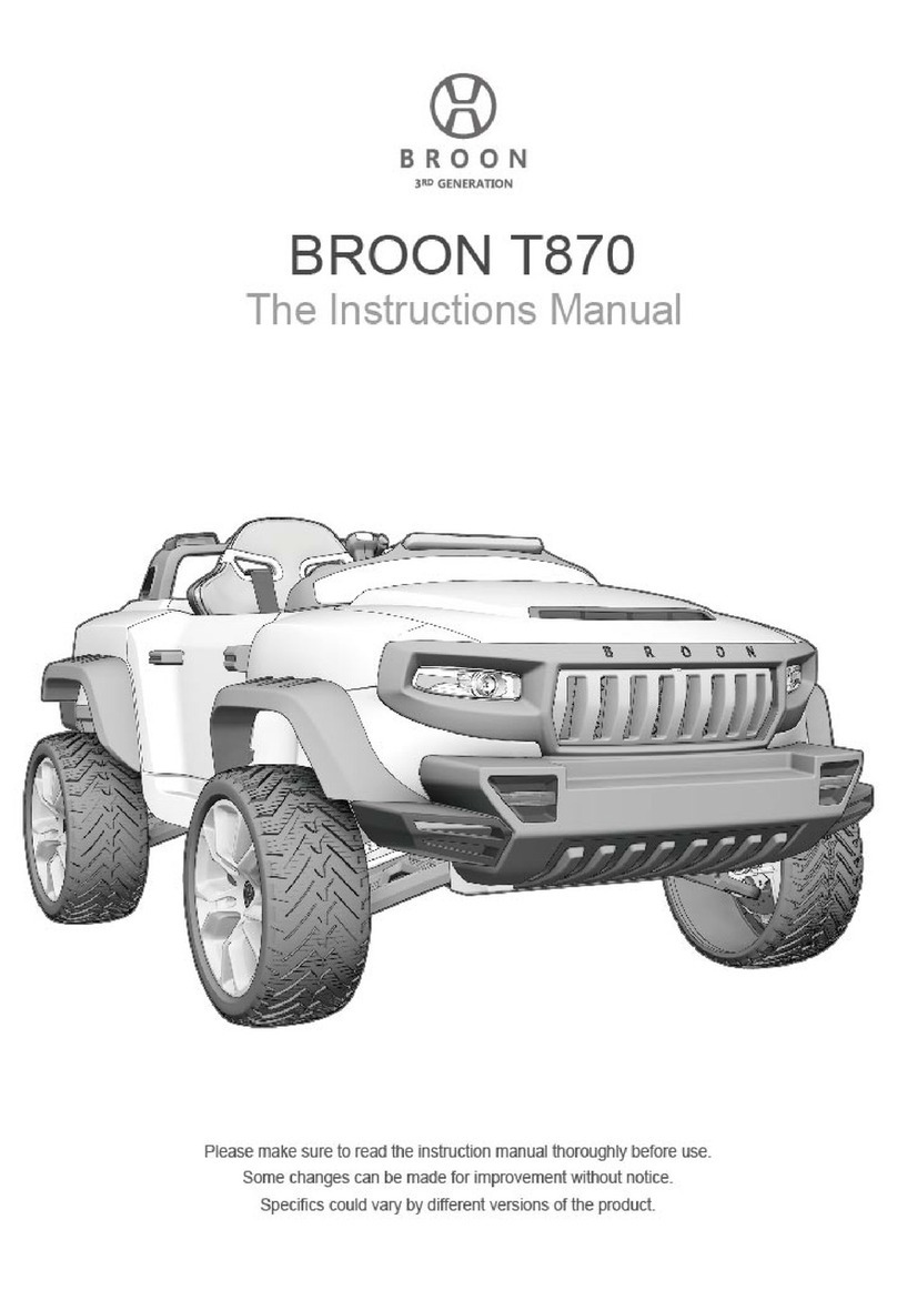
Broon T870 Intructions manual
