vii
Table of contents
Chapter 1 System units
Introduction .........................................................................................................1
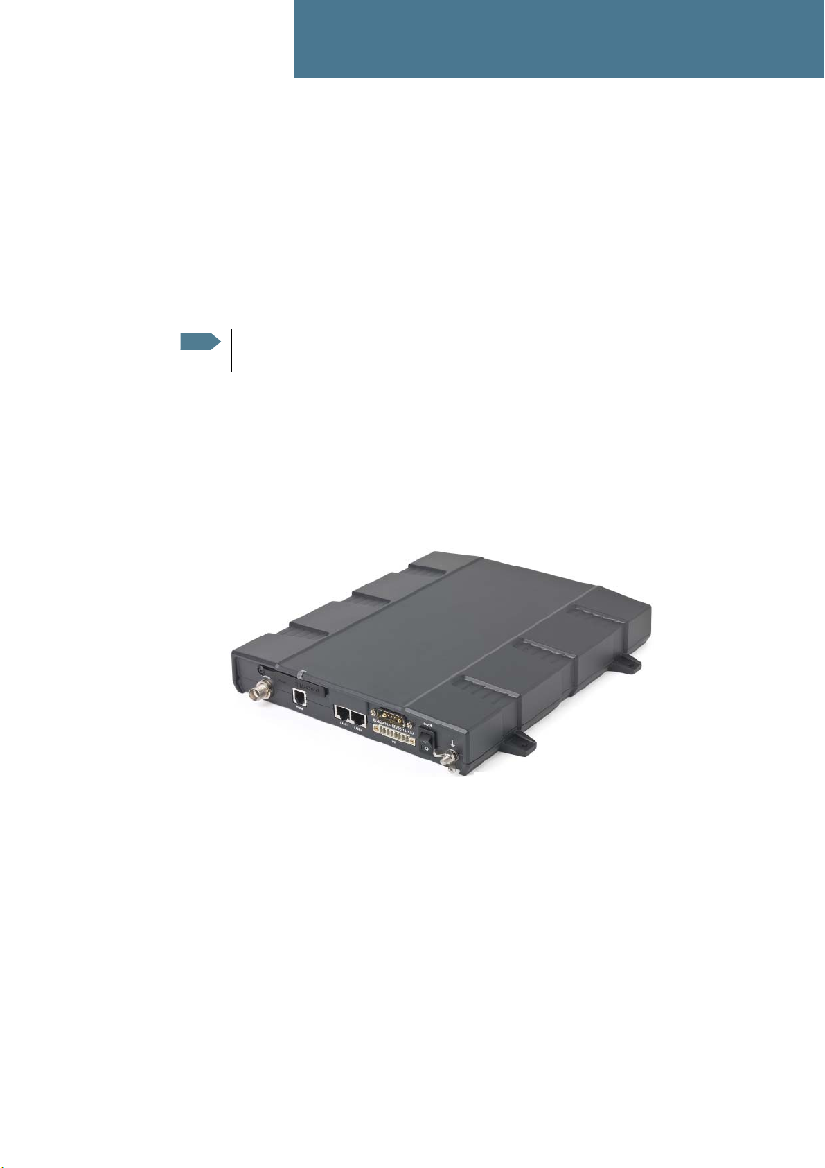
TracPhone FB150 terminal ...................................................................................1
TracPhone FB150 antenna ...................................................................................2
TracPhone IP Handset & Cradle ...........................................................................3
Chapter 2 Installing the system
Unpacking ...........................................................................................................4
Placing the antenna .............................................................................................5
Installing the antenna .........................................................................................12
Placing the terminal ...........................................................................................15
Installing the terminal .........................................................................................16
Chapter 3 Connecting power
Power source ....................................................................................................19
Power cable selection ........................................................................................19
Connecting power ..............................................................................................22
Chapter 4 Hardware interfaces
The connector panel ..........................................................................................24
Antenna interface on terminal .............................................................................25
DC power input ..................................................................................................26
Ground stud ......................................................................................................27
Analog Phone interface ......................................................................................28
LAN interface ....................................................................................................29
Discrete I/O interface .........................................................................................31
Chapter 5 Starting up the system
Using the SIM card ............................................................................................33
Powering the system ..........................................................................................35
Entering the SIM PIN for the terminal ..................................................................37
Operating the system .........................................................................................39
Chapter 6 Troubleshooting
Reset button ......................................................................................................40
Status signaling .................................................................................................42
Logging of events ..............................................................................................43
Appendix A Part numbers
System units .....................................................................................................44
Spare parts .......................................................................................................44