TRACTION BSU2-50 User manual

5353-M1-001-EN-02
BATTERY SUPPORT PRODUCTS
BSU2-50, CSU2-50, SSU2-50, BSU2-90,
BSU2-125 ALL VARIANTS
INSTRUCTION MANUAL

5353-M1-001-EN-02
Safety Guidelines
DANGER
General Safety Precautions
1. IMPORTANT SAFETY INSTRUCTIONS. IT IS OF
UTMOST IMPORTANCE THAT BEFORE USING
YOUR BATTERY SUPPORT PRODUCT, YOU READ
THIS MANUAL AND FOLLOW THE SAFETY AND
OPERATING INSTRUCTIONS EXACTLY. SAVE
THESE INSTRUCTIONS.
1.1. Use of an attachment not recommended or sold
by the support unit manufacturer may result in
a risk of fire, electric shock, or injury to persons.
1.2. To reduce the risk of damage to the electric plug
and cord, pull by the plug rather than by the
cord when disconnecting the support unit.
1.3. Position the AC and DC leads to avoid tripping
over them and to prevent damage by hood, or
moving engine parts. Protect from heat, oil and
sharp edges.
1.4. Do not operate the support unit if it has
received a sharp blow, been dropped or
otherwise damaged in any way. Take it to an
approved service centre.
1.5. Do not disassemble the battery support unit.
Take it to an approved repair centre when
repair is required. Incorrect reassembly may
result in a risk of electric shock or fire.
1.6. To reduce risk of electric shock, unplug the
charger from the AC outlet and disconnect DC
output leads before attempting any
maintenance or cleaning. Turning off the
controls will not reduce this risk.
1.7. Connect and disconnect the battery leads only
when the AC supply cord is disconnected.
1.8. Never place articles on or around the battery
support unit or locate the battery support unit
in a way that will restrict the flow of cooling air
through the enclosure.
1.9. An extension cord should not be used unless
absolutely necessary.
1.10. Have a damaged cord or plug replaced
immediately.
1.11. Do not expose the battery support unit to rain
or snow.
2. Personal Precautions
2.1. The battery support unit is not intended to
supply power to a low voltage electrical system
other than applications using rechargeable,
flooded, gel, or AGM type batteries. Do not use
the battery support unit to supply power to dry-
cell batteries as commonly used with home
appliances. These batteries may burst and cause
personal injury and property damage.
3. Grounding and AC Power cord connection
3.1. The battery support unit must be grounded to
reduce risk of electric shock. The battery
support unit is equipped with an electric cord
having an equipment grounding conductor and
a grounding plug. The plug must be plugged into
an outlet that is properly installed and grounded
in accordance with all local codes and
ordinances.
IF THE PLUG DOES NOT FIT THE OUTLET, HAVE
A PROPER OUTLET INSTALLED BY A QUALIFIED
ELECTRICIAN.
3.2 An extension cord should not be used unless
absolutely necessary. Use of an improper
extension cord could result in a risk of fire and
electric shock. If an extension cord must be
used, make sure:
a. that the pins on plugs of the extension cord are
the same number, size, and shape as those of
the plug on the support unit;
b. that the extension cable is properly wired and in
good electrical condition;
c. that the wire size is large enough for the AC
ampere rating of the support unit as specified in
the following table
Hazardous voltage.
An improper connection can
result in electric shock
To avoid electrical shock or burn,
never alter the battery support
units original AC cord and plug.
5353-M1-001-EN-02
Recommended minimum AWG size for extension cords for battery support units
AC input rating Amperes
AWG size of cord
Length of cord, M
7.5
15
30
45
8-10
18
14
12
8
10-12
16
14
10
8
12-14
16
12
10
8
14-16
16
12
10
8
16-18
14
12
10
8
4. Overview
4.1. The Traction range of Battery Support Units
convert nominally 110-120V ac 60Hz 8A to
13.8V dc 50A. This enables you to operate a 12V
nominal DC load up to the units rated output
current as demanded by the attached load.
4.2. Each Battery Support Unit has been designed
with high quality components to help ensure
years of continuous use. The Support Units are
protected by multiple protection features in
order to ease of use:
Reverse polarity protection –the centre LED
should show green for good or red for incorrect
connection.
Over-current protection
Over temperature protection
Short circuit protection
Backward voltage protection –if the voltage at
the terminals is higher than the Support Unit
supply a relay will be heard cutting in and then
cutting out to check voltage level.
5. Installation
There are no components within the Battery
Support Units that, in their normal operation,
produce arcs or sparks. All electronic devices
have some potential for generating sparks in the
event of failure. Therefore, never install this
device in the same compartment with
flammable items such as gasoline or batteries.
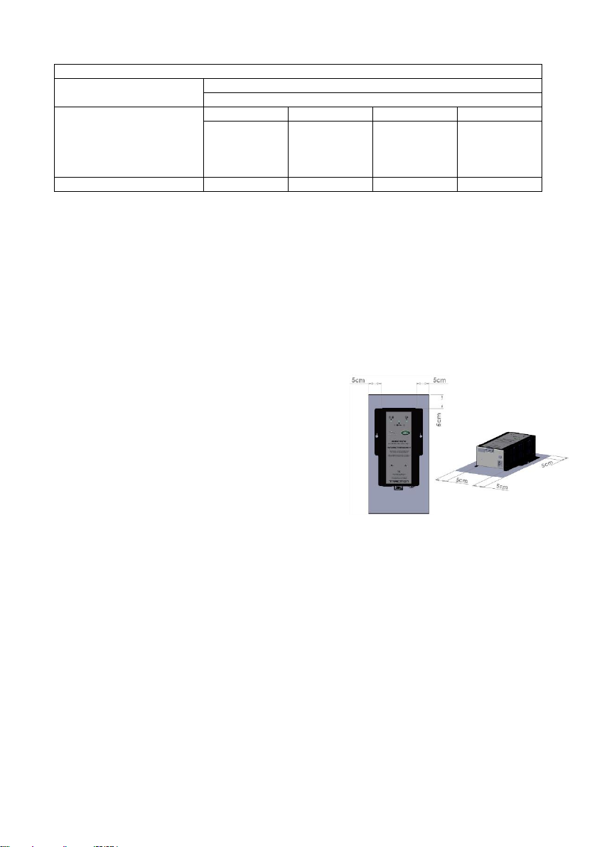
5.1. Installation Location
BSU2-50 and BSU2-125 have been designed to
be trolley mounted (Part number JLR-Trolley-
US). The trolley comes complete with mounting
bracket. Battery support units should not be
rested in engine bay due to risk of damage
either to vehicle or equipment. Showroom
support unit SSU2-50 has been designed to sit
under the supported vehicle. Ensure that unit is
placed on fitted rubber runners and that there
is at least 5cm of clear space on all sides
excluding base. Ensure the mains socket is near
the equipment and easily accessible at all times.
The unit can be wall mounted in a vertical
orientation only with the connections at the
bottom.
Neither BSU2 or SSU2 should not be positioned
so that the label is either upside down or
invisible.
5.2. Connecting to a vehicle
Please follow dealer standards guidelines for
connection methods. Traction units are supplied
with vehicle specific adapters that should be
used at all times. Failure to use the adapters in
the positions prescribed could result in
excessive heat being generated in the lead set
leading to premature failure of leads and low
voltage output.

5353-M1-001-EN-02
Output leads are connected using the polarised
connectors on the unit and lead set.
Ensure units is disconnected from AC power
before connecting to vehicle. Only when the
central “polarity” led lights green should AC
power be connected.
5.3. Powering the unit
The primary method for powering the support
unit is via the AC power cord. The switch on the
unit is primarily designed to cut off the output
to DC leads.
CSU2 ONLY
Battery Support Mode:
Ensure output leads are not connected to CSU2
and unit is disconnected from mains power.
Connect output leads to vehicle battery
terminals.
Power up CSU2.
Wait for 2 beeps and connect output leads to
CSU2 via yellow connector.
Showroom Support Mode:
Ensure output leads are not connected to CSU2
and unit is disconnected from mains power.
Connect output leads to vehicle battery
terminals.
Connect output leads to CSU2 via yellow
connector.
Power up CSU2.
5.4. Disconnecting from vehicle
Ensure unit is switched off AND AC power is
disconnected before disconnecting leads from
vehicle

5353-M1-001-EN-02
6. Status beeps:
BSU beeps repeat every 4 seconds.
Light load detected 2 beeps
Battery error (high impedance) 3 beeps - Check connections and battery.
Connection Error 4 beeps - Check connections.
SSU beeps repeat every 15 minutes.
Battery error (low voltage) 2 beeps - Check connections and battery.
Battery error (high impedance) 3 beeps –Check connections and battery.
Connection Error 4 beeps –Check connections.
7. Symbols
The following symbols appear on the battery support units:
O/I
AC Power - Illuminated when supply is reaching unit
+ +
Polarity - Green when good
Red when reversed
Output - Illuminated when output is active
8. Warranty and Service
For technical support call 866-628-5508
or email oetech@service-solutions.com
For repair service, go to
repairtrack.bosch-automotive.com
or call 800-344-4013
9. Manufacturer Information
Traction products are manufactured by:
Traction Chargers
Roundway Hill Business Centre
Devizes
Wiltshire
SN10 2LT UK
+44(0)330 022 7822
admin@tractioncharger.com

5353-M1-001-EN-02
10. General
This symbol is used on products that contain a hazardous element and
therefore cannot be thrown away in the normal way. it appears on
Electrical and Electronic Equipment (EEE) as part of the WEEE (Waste
EEE) directive –separate collection facilities will be set up to divert WEEE
away from landfill; funded by producers and retailers of EEE
11. Technical Specification
Environmental Information
Parameter
BSU2-50/B
SSU2-50/B
Working Temp. °C
+0 to +40
Working Humidity
20 –90% non-condensing
Storage Temp. °C
-40 - +85
Storage Humidity
10 –95% RH
Input Voltage Range
110 –120VAC
Inrush Current (max)
8A/110VAC
O/P Rated Current
50A
O/P Rated Power
600W
Output Voltage (Typ)
13.8V
Dimensions LxWxH
280 x 190 x 90
This manual suits for next models
4
Table of contents


