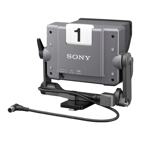
Sony HDCE-TX30 User manual

SERVICE MANUAL
1st Edition
IP CAMERA EXTENSION ADAPTOR
HDCE-TX30
利用条件:
①本情報はソニー製品の販売、設置、設定、使用の目的でのみご利用ください。かかる目的以外での利用を禁止します。
② 著作者の事前の書面による許可なく、本情報の全部または一部の複写、複製、転載、改変、翻訳、送信等を禁止します。
情報改訂:
本情報は、当社の裁量により、予告なく変更されることがあります。ご使用される場合、本情報が最新の情報であることを確認のうえ、
ご使用ください。
Conditions of Use:
(1) Please use this information only for the purpose of sales, installation, configuration, and use of Sony products. Using this information
for any purpose other than the purpose described foregoing is forbidden.
(2) Do not copy, replicate, reproduce, alter, translate, transmit, sell, lease, or distribute this information in whole or in part without the prior
written permission of the author.
Revision of Information:
This information may be changed or updated at any time without any prior notice. Please confirm that this information is up-to-date before
using it.

Model Name Serial No.
HDCE-TX30/L (SY): LEMO Optical Fiber Connector 10001 and Higher
HDCE-TX30/T (E): Tajimi Optical Fiber Connector 30001 and Higher
警告
このマニュアルは,サービス専用です。
お客様が,このマニュアルに記載された設置や保守,点検,修理などを行うと感電や火災,
人身事故につながることがあります。
危険をさけるため,サービストレーニングを受けた技術者のみご使用ください。
WARNING
This manual is intended for qualified service personnel only.
To reduce the risk of electric shock, fire or injury, do not perform any servicing other than that
contained in the operating instructions unless you are qualified to do so. Refer all servicing to
qualified service personnel.
WARNUNG
Die Anleitung ist nur für qualifiziertes Fachpersonal bestimmt.
Alle Wartungsarbeiten dürfen nur von qualifiziertem Fachpersonal ausgeführt werden. Um die
Gefahr eines elektrischen Schlages, Feuergefahr und Verletzungen zu vermeiden, sind bei
Wartungsarbeiten strikt die Angaben in der Anleitung zu befolgen. Andere als die angegeben
Wartungsarbeiten dürfen nur von Personen ausgeführt werden, die eine spezielle Befähigung
dazu besitzen.
AVERTISSEMENT
Ce manual est destiné uniquement aux personnes compétentes en charge de l’entretien. Afin
de réduire les risques de décharge électrique, d’incendie ou de blessure n’effectuer que les
réparations indiquées dans le mode d’emploi à moins d’être qualifié pour en effectuer d’autres.
Pour toute réparation faire appel à une personne compétente uniquement.
警告
本機は電源スイッチを備えていません。
万一,異常が起きた際に,お客様が電源を切ることが
できるように,設置の際には,機器近くの固定配線内
に専用遮断装置を設けるか,機器使用中に,容易に抜
き差しできるコンセントに電源プラグを接続してくだ
さい。
WARNING
This unit has no power switch.
When installing the unit, incorporate a readily accessible
disconnect device in the fixed wiring, or connect the
power cord to a socket-outlet which must be provided
near the unit and easily accessible, so that the user can
turn off the power in case a fault should occur.
WARNUNG
Dieses Gerät hat keinen Netzschalter.
Beim Einbau des Geräts ist daher im Festkabel
ein leicht zugänglicher Unterbrecher einzufügen,
oder das Netzkabel muß mit einer in der Nähe
des Geräts befindlichen, leicht zugänglichen
Wandsteckdose verbunden werden, damit sich bei
einer Funktionsstörung die Stromversorgung zum Gerät
jederzeit unterbrechen läßt.
For safety, do not connect the connector for peripheral
device wiring that might have excessive voltage to the
following port(s).
: LAN connector
: LAN COM connector
: NETWORK TRUNK connector
Follow the instructions for the above port(s).
安全のために,周辺機器を接続する際は,過大電圧を
持つ可能性があるコネクターを以下のポートに接続し
ないでください。
:LAN 端子
: LAN COM 端子
:NETWORK TRUNK 端子
上記のポートについては本書の指示に従ってください。
For kundene i Norge
Dette utstyret kan kobles til et IT-strømfordelingssystem.

CAUTION
RISK OF ELECTRIC SHOCK
The fuse of the primary circuit of this product may be
connected on the neutral wire side.
Disconnect the unit from the power supply to prevent
electric shock when repairing.
ATTENTION
RISQUE D’ÉLECTROCUTION
Le fusible du circuit primaire de ce produit peut être
connecté sur le côté de fil neutre.
Déconnectez l’appareil de l’alimentation pour éviter
un choc électrique lors de la réparation.
注意
感電の危険があります。
本製品の一次回路のヒューズが,中性線側に接続さ
れる可能性があります。
修理時の感電を防ぐため,本機を主電源から切り離
してください。
This IP Camera Extension Adaptor is classified as a CLASS 1 LASER PRODUCT.
CLASS 1 LASER PRODUCT
LASER KLASSE 1 PRODUKT
LUOKAN 1 LASERLAITE
KLASS 1 LASER APPARAT
Use of controls or adjustments or performance
of procedures other than those specified herein
may result in hazardous radiation exposure.
CAUTION

CAUTION
Danger of explosion if battery is incorrectly replaced.
Replace only with the same or equivalent type rec-
ommended by the manufacturer.
When you dispose of the battery, you must obey the
law in the relative area or country.
ATTENTION
Il y a danger d’explosion s’il y a remplacement incor-
rect de la batterie. Remplacer uniquement avec
une batterie du même type ou d’un type équivalent
recommandé par le constructeur.
Lorsque vous mettez la batterie au rebut, vous devez
respecter la législation en vigueur dans le pays ou la
région où vous vous trouvez.
VORSICHT
Explosionsgefahr bei Verwendung falscher Batterien.
Batterien nur durch den vom Hersteller empfohlenen
oder einen gleichwertigen Typ ersetzen.
Wenn Sie die Batterie entsorgen, müssen Sie die
Gesetze der jeweiligen Region und des jeweiligen
Landes befolgen.
注意
指定以外の電池に交換すると,破裂する危険があり
ます。
必ず指定の電池に交換してください。
使用済みの電池は,国または地域の法令に従って
処理してください。
FÖRSIKTIGHET!
Fara för explosion vid felaktigt placerat batteri.
Byt endast mot samma eller likvärdig typ av batteri,
enligt tillverkarens rekommendationer.
När du kasserar batteriet ska du följa rådande lagar
för regionen eller landet.
PAS PÅ
Fare for eksplosion, hvis batteriet ikke udskiftes
korrekt.
Udskift kun med et batteri af samme eller tilsvarende
type, som er anbefalet af fabrikanten.
Når du bortskaffer batteriet, skal du følge
lovgivningen i det pågældende område eller land.
HUOMIO
Räjähdysvaara, jos akku vaihdetaan virheellisesti.
Vaihda vain samanlaiseen tai vastaavantyyppiseen,
valmistajan suosittelemaan akkuun.
Noudata akun hävittämisessä oman maasi tai
alueesi lakeja.
FORSIKTIG
Eksplosjonsfare hvis feil type batteri settes i.
Bytt ut kun med samme type eller tilsvarende
anbefalt av produsenten.
Kasser batteriet i henhold til gjeldende avfallsregler.

1
Table of Contents
Section 1 Service Overview..................................................................................................................................................................4
1-1. Location of Printed Wiring Boards...............................................................................................................................................4
1-2. Functions of Onboard Switches and LED Indicators....................................................................................................................5
1-2-1. NET-37 Board........................................................................................................................................................................5
1-2-2. VIF-82 Board.........................................................................................................................................................................7
1-3. Notes on Replacement of Circuit Board .......................................................................................................................................8
1-3-1. AT-195 Board, VIF-82 Board and Power Unit (RE-345 Board).............................................................................................8
1-4. Cautions when Replacing the Lithium Battery .............................................................................................................................9
1-4-1. Replacing Procedure..............................................................................................................................................................9
1-5. Cleaning of Connector/Cable......................................................................................................................................................10
1-5-1. When the Optical Connector Cleaner (Commercially Available) isAvailable .....................................................................10
1-5-2. When the Optical Connector Cleaner (Commercially Available) is not Available (Connectors/Cables of LEMO) .............11
1-5-3. When the Optical Connector Cleaner (Commercially Available) is notAvailable (Connector of Tajimi Electronics Co.,
Ltd./Cable)......................................................................................................................................................................................12
1-5-4. When the Optical Connector Cleaner (Commercially Available) is not Available (Connector)...........................................14
1-6. Service Tools/Measuring Equipment List...................................................................................................................................14
1-6-1. Service Fixtures ...................................................................................................................................................................14
1-7. PLD ............................................................................................................................................................................................15
1-7-1. Corresponding PLDs............................................................................................................................................................15
1-7-2. Upgrading PLD Data ...........................................................................................................................................................15
1-8. Flexible Flat Cable and Coaxial Cable........................................................................................................................................16
1-8-1. Disconnecting/Connecting Flexible Flat Cable....................................................................................................................16
1-8-2. Disconnecting/Connecting Fine-Wire Coaxial Cable...........................................................................................................17
1-8-3. Connecting/Disconnecting Coaxial Cable............................................................................................................................20
1-9. Circuit Protective Devices..........................................................................................................................................................21
1-9-1. Fuse......................................................................................................................................................................................21
1-9-2. Circuit Protection Element...................................................................................................................................................21
Section 2 Replacement of Main Parts.................................................................................................................................................22
2-1. Notes on Replacing the Parts......................................................................................................................................................22
2-1-1. Tightening Torque................................................................................................................................................................22
2-2. Top Cover ...................................................................................................................................................................................23
2-3. NET-37 Board Assembly ............................................................................................................................................................25
2-3-1. NET-37 Board......................................................................................................................................................................28
2-4. Front Panel Assembly.................................................................................................................................................................30
2-4-1. LE-436 Board ......................................................................................................................................................................31
2-4-2. FP-322 Board.......................................................................................................................................................................32
2-4-3. LE-437 Board ......................................................................................................................................................................34
2-4-4. SW-1775 Board....................................................................................................................................................................35
2-4-5. Filter.....................................................................................................................................................................................36

2
2-5. VIF-82 Board Assembly.............................................................................................................................................................38
2-5-1. VIF-82 Board/AT-195 Board................................................................................................................................................40
2-5-2. Coaxial Connector Converter (BNC Type) ..........................................................................................................................44
2-6. Lithium Battery...........................................................................................................................................................................47
2-7. Optical Multi Fiber Cables..........................................................................................................................................................48
2-7-1. LEMO Connector Assembly................................................................................................................................................48
2-7-2. TAJIMI Connector Assembly...............................................................................................................................................50
2-8. CN-4132 Board...........................................................................................................................................................................51
2-9. DC Fan (60 x 15)........................................................................................................................................................................52
2-10. AC Inlet ....................................................................................................................................................................................54
2-11. DC Fan (60 Square) (Front)......................................................................................................................................................56
2-12. DC Fan (60 Square) (Rear).......................................................................................................................................................58
2-13. Power Block .............................................................................................................................................................................60
2-13-1. RE-345 Board ....................................................................................................................................................................63
2-13-2. DC Fan (Power).................................................................................................................................................................65
2-13-3. PS-939 Board.....................................................................................................................................................................66
Section 3 Software Update .................................................................................................................................................................67
3-1. Upgrading Software Programs....................................................................................................................................................67
3-1-1. Upgrading Application.........................................................................................................................................................67
3-1-2. Upgrading OS ......................................................................................................................................................................67
3-1-3. Upgrading Update Software.................................................................................................................................................68
3-1-4. Forced Version Update.........................................................................................................................................................69
Section 4 Menu Settings.....................................................................................................................................................................70
4-1. Preparations................................................................................................................................................................................70
4-1-1. Display/Hide the Status Screen............................................................................................................................................70
4-1-2. Starting and Exiting the SERVICE Menu ............................................................................................................................70
4-1-3. Changing Setting Values......................................................................................................................................................71
4-2. SERVICE Menu..........................................................................................................................................................................72
4-2-1. SERVICE Menu List............................................................................................................................................................72
4-2-2. Description of SERVICE Menu...........................................................................................................................................73
Section 5 Circuit Description..............................................................................................................................................................78
5-1. Circuit Description of Each Board..............................................................................................................................................78
5-1-1. AT-195 Board.......................................................................................................................................................................78
5-1-2. CN-4131 Board....................................................................................................................................................................78
5-1-3. CN-4132 Board....................................................................................................................................................................78
5-1-4. FP-322 Board.......................................................................................................................................................................78
5-1-5. LE-436 Board ......................................................................................................................................................................78
5-1-6. LE-437 Board ......................................................................................................................................................................78
5-1-7. NET-37 Board......................................................................................................................................................................78
5-1-8. SW-1775 Board....................................................................................................................................................................78
5-1-9. VIF-82 Board.......................................................................................................................................................................79

3
Section 6 Spare Parts..........................................................................................................................................................................81
6-1. Note on Repair Parts...................................................................................................................................................................81
6-2. Exploded Views..........................................................................................................................................................................82
Cover..............................................................................................................................................................................................82
NET-37 Board ................................................................................................................................................................................83
Front Panel .....................................................................................................................................................................................84
VIF-82 Board .................................................................................................................................................................................85
DC Fans..........................................................................................................................................................................................86
Chassis............................................................................................................................................................................................87
Power Block...................................................................................................................................................................................88
6-3. Supplied Accessories ..................................................................................................................................................................89
Section 7 Diagrams.............................................................................................................................................................................90
Overall (1/3).......................................................................................................................................................................................90
Overall (2/3).......................................................................................................................................................................................91
Overall (3/3).......................................................................................................................................................................................92
Frame Wiring.....................................................................................................................................................................................93
Revision History....................................................................................................................................................................................94

4
Section 1
Service Overview
1-1. Location of Printed Wiring Boards
RE-345
PS-939
CN-4132
CN-4131
VIF-82
NET-37
AT-195
LE-436
LE-437
FP-322
SW-1775

5
1-2. Functions of Onboard Switches and LED Indicators
1-2-1. NET-37 Board
Switch
Note
Do not change the setting of “Factory use” switch.
Ref. No.
Name
Bit
Function
Factory default setting
S0401
-
1
Factory use
OFF
S0601
-
1 to 4
Factory use
OFF (ALL)
S1101
-
1 to 4
Factory use
OFF (ALL)
D0201
D0202
D0203
D0204
D0205
D2101
D0401
D1201
D0206
D0207
D0208
D1604
D1603
D1602
D1601
D1608
D1607
D1606
D1605
D0604
D0603
D0602
D0601
D0608
D0607
D0606
D0605
NET-37 Board (SideA)
S1101 S0601
S0401

6
LED
Ref. No.
Name
Color
Description
Normal State (Power On)
D0201
TDIS_A
Red
Factory use
Inconstant
D0202
TFAULT_A
Red
Factory use
Inconstant
D0203
MOD ABS_A
Red
Factory use
Inconstant
D0204
RX_LOS_A
Red
Factory use
Inconstant
D0205
TDIS_B
Red
Factory use
Inconstant
D0206
TFAULT_B
Red
Factory use
Inconstant
D0207
MOD ABS_B
Red
Factory use
Inconstant
D0208
RX_LOS_B
Red
Factory use
Inconstant
D0401
PGOOD
Green
This LED lights when the power is supplied to the board.
On
D0601
BiBi-LED7
Green
Factory use
Inconstant
D0602
BiBi-LED6
Green
Factory use
Inconstant
D0603
BiBi-LED5
Green
Factory use
Inconstant
D0604
BiBi-LED4
Green
Factory use
Inconstant
D0605
BiBi-LED3
Green
Factory use
Inconstant
D0606
BiBi-LED2
Green
Factory use
Inconstant
D0607
BiBi-LED1
Green
Factory use
Inconstant
D0608
BiBi-LED0
Green
Factory use
Inconstant
D1201
NET2_CONF_DONE
Red
This LED goes out when NET2_FPGA (IC002) is
normally completed configuration.
Off
D1601
NENE-LED7
Green
Factory use
Inconstant
D1602
NENE-LED6
Green
Factory use
Inconstant
D1603
NENE-LED5
Green
Factory use
Inconstant
D1604
NENE-LED4
Green
Factory use
Inconstant
D1605
NENE-LED3
Green
Factory use
Inconstant
D1606
NENE-LED2
Green
Factory use
Inconstant
D1607
NENE-LED1
Green
Factory use
Inconstant
D1608
NENE-LED0
Green
Factory use
Inconstant
D2101
NET1-CONF_DONE
Red
This LED goes out when NET1_FPGA (IC001) is
normally completed configuration.
Off

7
1-2-2. VIF-82 Board
Switch
Note
Do not change the setting of “Factory use” switch.
Ref. No.
Name
Bit
Description
Factory default setting
S1101
DebugSW
1 to 4
For debugging IC1101
OFF (ALL)
S1401
DebugSW
1 to 4
For debugging IC1401
OFF (ALL)
LED
Ref. No.
Name
Color
Description
Normal State (Power On)
D203
PG3-1
Green
PWRGOOD of IC004 power output
On
D204
PG1
Green
PWRGOOD of power supply IC group 1
On
D205
PG2
Green
PWRGOOD of power supply IC group 2
On
D206
PG3-2
Green
PWRGOOD of IC003 power output
On
D401
TDIS
Red
This LED lights when the optical module output is
activated.
On
D402
TFAULT
Red
This LED lights when an optical module error is detected.
Off
D403
MOD DEF
Red
Unlit when the optical module is connected.
Off
D404
RX_LOS
Red
Unlit when the optical module is receiving light.
Off
D901
EXT
Green
Lit during locking to the external REF signal.
On
D1101
DebugLED
Green
For debugging IC1101
Blinks
D1102
DebugLED
Green
For debugging IC1101
Blinks
D1103
DebugLED
Green
For debugging IC1101
Blinks
D1104
DebugLED
Green
For debugging IC1101
Blinks
D1301
PLD1DONE
Red
This LED goes out after ConfigDone of IC1101 is
performed.
Off
D1401
DebugLED
Green
For debugging IC1401
Blinks
D1402
DebugLED
Green
For debugging IC1401
Blinks
D1403
DebugLED
Green
For debugging IC1401
Blinks
D1404
DebugLED
Green
For debugging IC1401
Blinks
D2001
PLD2DONE
Red
This LED goes out after ConfigDone of IC1700 is
performed.
Off
A
1
2
3
BCDE
FGH
VIF-82 Board (SideA)
S1101
D204
D205
D203
D206
A1
2
3
BC
D
E
F
G
H
VIF-82 Board (Side B)
D1104
D1301
D1103
D1102
D1101
D1404
D2001
D1403
D1402
D1401
D404
D901
D403
D402
D401
S1401

8
1-3. Notes on Replacement of Circuit Board
1-3-1. AT-195 Board, VIF-82 Board and Power Unit (RE-345 Board)
AT-195 board, VIF-82 board, and RE-345 board store the important information including the model name and serial number.
After replacing the AT-195 board, VIF-82 board, and RE-345 board, perform RESTORE on the [04 <SERIAL NUMBER>] page of
the SERVICE menu. (Refer to “4-2-2. Description of SERVICE Menu”.)

9
1-4. Cautions when Replacing the Lithium Battery
The lithium battery is installed on the VIF-82 board. This lithium battery is used to back up the real-time clock (RTC).
RTC stops operating when the battery life expires. Replace the battery and reset the DATE & TIME (M03) of the MAINTENANCE
menu. (Refer to OPERATION MANUAL.)
Part No.
Name
Usage
1-756-134-1X
Lithium Battery (ML621 (U))
For internal clock
CAUTION
Ensure that the battery is installed with + and – poles connected to the correct terminals. An incorrect connection may cause an
explosion or leakage of fluid.
1-4-1. Replacing Procedure
Preparation
1. Remove the top cover. (Refer to “2-2. Top Cover”.)
Procedure
1. Remove the lithium battery from the four hooks of the battery holder.
Note
When installing the lithium battery, install it to the orientation shown in the figure.
2. Install the removed parts by reversing the steps of removal.
!
Lithium Battery
Hooks
Hooks
Lithium Battery
Battery holder
VIF-82 board

10
1-5. Cleaning of Connector/Cable
• Lit in two green indicators (right): Receive signal condition is very good.
• Lit in one green indicator (2nd from right): Receive signal condition is OK.
• Lit in one yellow indicator (2nd from left): Receive signal level is weak.
• Lit in one red indicator (left): Receive signal level is severely degraded.
When lit in red, be sure to clean the optical contact portions.
When lit in yellow, cleaning is recommended.
The attenuation of the photo-receptive level may cause transmission error. Clean optical contact portions proceeding as follows.
The optical contact portion exist in the optical connector on this unit or camera control, and in the optical/electrical cables.
1-5-1. When the Optical Connector Cleaner (Commercially Available) is Available
Fixtures
• Optical connector cleaner (commercially available)
- Product name: CLETOP ®
- 14100402 or 14100403 or equivalent (stick type)
- 14100402: 2.0 mm
- 14100403: 2.0/2.5 mm double ended
Tip
• Alcohol is not necessary during cleaning.
• Number of possible wipes is one cleaning per a piece. Do not reuse it.
Cleaning Procedure
Male connector
Clean the tip of the optical contacts (white) using the optical connector cleaner.
Female connector
1. Insert the optical connector cleaner straight.
2. Apply sufficient pressure (approximately 600 g to 700 g) to ensure that the optical contact is a little depressed.
3. While pressing the optical connector cleaner against the tip of the optical contact, rotate the optical connector cleaner by 4 to 5
turns clockwise. Holding the optical connector cleaner at around its support facilitates to apply the pressure.
Optical contacts (white)
Optical connector cleaner
Support
Alignment sleeve

11
Connector
Clean the tip of the optical contacts (white) using the optical connector cleaner.
1-5-2. When the Optical Connector Cleaner (Commercially Available) is not Available
(Connectors/Cables of LEMO)
Clean the LEMO connectors and cables using the following procedure.
Fixtures
• Alignment sleeve remover HC-001 (for female connector)
Sony Part No.: J-6480-010-A or DCC.91.312.5LA manufactured by LEMO, or equivalent
Note
Insert the shorter nose end when removing/installing the alignment sleeve. This fixture contains shock absorber portion. Grasp
not the shock absorber portion of the remover but the handle in use.
• Alcohol (commercially available)
• Cotton swabs (commercially available)
Note
Use a cotton swab whose diameter is about 4 mm. If a cotton swab whose diameter exceeds 5 mm is used, the cotton swab
cannot be inserted into the end of the connector and the tip of the optical contact cannot be cleaned.
Cleaning Procedure
Male connector
Clean the tip of the optical contacts (white) with a cotton swab moistened with alcohol.
Female connector
The optical contacts for female connector are in an unexposed state. In cleaning, it is necessary to be exposed by removing the
alignment sleeve in advance. Proceed as follows.
1. Insert the alignment sleeve remover into the alignment sleeve in the straight line and turn it clockwise.
2. When the turn stops, pull out the remover in the straight line forcedly.
Optical contact
(white)
Shock
absorber portion
Insert the shorter nose end
Handle
Optical contacts (white)
Alignment sleeve
Alignment sleeve remover

12
Note
The alignment sleeve can be removed/reinstalled with the sleeve itself attached to the tip of the remover. Great care should be
taken so as not to lose or damage the alignment sleeve.
Alignment sleeve: Sony Part No.: 9-980-074-01
3. Clean the tip of the optical contacts (white) with a cotton swab moistened with alcohol.
4. Insert the remover with the alignment sleeve attached to its tip, and push it until it clicks.
5. Rotate the remover counterclockwise to install the alignment sleeve, and extract the remover.
1-5-3. When the Optical Connector Cleaner (Commercially Available) is not Available
(Connector of Tajimi Electronics Co., Ltd./Cable)
Clean the connectors of Tajimi Electronics and cables using the following procedure.
Fixtures
• Alcohol (commercially available)
• Cotton swabs (commercially available)
Note
Use a cotton swab whose diameter is about 4 mm. If a cotton swab whose diameter exceeds 5 mm is used, the cotton swab
cannot be inserted into the end of the connector and the tip of the optical contact cannot be cleaned.
Cleaning Procedure
Male connector
Clean the tip of the optical contacts (white) with a cotton swab moistened with alcohol.
Female connector
The optical contacts for female connector are in an unexposed state. In cleaning, it is necessary to be exposed by removing the
adapter in the connector in advance. Proceed as follows.
1. Loosen the adapter pin at the center of the connector counterclockwise with a screwdriver.
Note
If there is no screwdriver, use the plate attached to the connector cap.
Alignment sleeve
Optical contacts (white)

13
2. Pull the adapter pin out of the connector in the arrow direction. Remove the adapter from the connector.
3. Clean the optical contacts (white) with a cotton swab moistened with alcohol.
4. Match the positioning marks of the adapter and the connector, and then push the adapter into the connector.
Note
Push the adapter until the confirmation groove comes in sight as shown in the figure.
5. Tighten the adapter pin clockwise until being lightly fixed.
Note
Do not fully tighten the adapter pin. (Extent where adapter pin is lightly fixed)
Adapter
Adapter pin
Optical contacts (white)
Adapter
Positioning marks
Confirmation
groove

14
1-5-4. When the Optical Connector Cleaner (Commercially Available) is not Available
(Connector)
Fixtures
• Alcohol (commercially available)
• Cotton swabs (commercially available)
Note
Use a cotton swab whose diameter is about 4 mm. If a cotton swab whose diameter exceeds 5 mm is used, the cotton swab
cannot be inserted into the end of the connector and the tip of the optical contact cannot be cleaned.
Connector
Clean the tip of the white optical contacts with a cotton swab moistened with alcohol.
1-6. Service Tools/Measuring Equipment List
1-6-1. Service Fixtures
Part No.
Name
Usage/Note
J-6480-010-A
Alignment sleeve remover HC-001
For female optical connector (LEMO® DCC. 91.312.5LA or equivalent)
—
Cotton swab
Commercially available, for cleaning optical contact block (4 mm or less
in diameter)
Optical contact (white)

15
1-7. PLD
This unit uses the PLD (Programmable Logic Device) that supports USB drive to write and rewrite the internal data.
If the part listed below needs to be replaced or to be upgraded, contact your local Sony Sales Office/Service Center.
Note
The part number of PLD (or ROM for PLD) in which data is not written yet, is shown in “Spare Parts”.
Therefore, if part replacement is required, write the data by the following procedure.
In the case of the PLD type that runs on the program stored in external ROM, data needs not to be written only by replacing the part
if the specific PLD only is defective.
Tip
The USB connector for connection to a USB drive is located to the lower right of the front panel. Detach the USB connector lid to
connect the USB drive.
1-7-1. Corresponding PLDs
Board name
Ref. No.
File name
NET-37
IC001
hdcetx50_net1.pkg
IC002
hdcetx50_net2.pkg
VIF-82
IC1101
hdcetx50_sy.pkg
IC1401
hdcetx50_vif82_tx.pkg
1-7-2. Upgrading PLD Data
Equipment Required
• USB drive (commercially available)
Tip
For recommended USB drive, contact your local Sony Sales Office/Service Center.
Preparation
Copy the PLD update data to the USB drive using the following procedure.
Note
For how to obtain the data files for update, contact your local Sony Sales Office/Service Center.
1. Create the following directory in the USB drive.
\MSSONY\PRO\CAMERA\HDCETX50
2. Copy the data files for PLD update to be updated to the directory created.
Procedure
1. Connect the USB drive that contains the program for update to the USB connector of this unit.
2. Turn on the power of the unit.
3. Display the PLD PACKAGE page of the SERVICE menu.
Tip
For the SERVICE menu, refer to “4-2. SERVICE Menu”.
4. Select the PLD to be upgraded and then press the control knob.
5. A message “UPDATE OK?” appears. Select “YES.”
The unit restarts automatically and the version update starts.
Upon completion of the version update, a message “UPDATE SUCCEEDED” appears.

16
1-8. Flexible Flat Cable and Coaxial Cable
1-8-1. Disconnecting/Connecting Flexible Flat Cable
Note
• Be very careful not to fold flexible flat cables. Life of flexible flat cable will be significantly shortened if it is folded.
• Each flexible flat cable has conductive side and insulated side. If the flexible flat cable is connected in the wrong orientation of
the conductive side and the insulated side, the circuit will not function.
• Insert the flexible flat cable straight.
• Check that the conductive side of the flexible flat cable is not contaminated.
Type A
Disconnecting
1. Open the latch of the connector in the direction of arrow A to unlock.
2. Disconnect the flexible flat cable.
Connecting
1. Insert the flexible flat cable firmly as far as it will go with the insulating surface facing front.
2. Close the latch of the connector in the direction of arrow B to lock the flexible flat cable.
Type B
Disconnecting
1. Open the latch of the connector in the direction of arrow A to unlock.
2. Disconnect the flexible flat cable.
Flexible Flat Cable
Connector
Latch
A
Insulated side Latch
Flexible Flat Cable
BConnector
A
Flexible card wire
Connector
Latch
Table of contents
Other Sony Camera Accessories manuals

Sony
Sony GP-VPT2BT User manual

Sony
Sony UNI-PMA1 User manual

Sony
Sony Alpha HVL-MT24AM User manual

Sony
Sony ADP-AMA User manual

Sony
Sony XC-ST30 User manual

Sony
Sony VF-72CPK User manual

Sony
Sony VCT-D480RM User manual

Sony
Sony SPK-WB Marketing User manual

Sony
Sony DSC-W7/B User manual

Sony
Sony SPK-CXB User manual