TRADEFORCE TRFSD240PE User manual

MODEL TRFSD240PE & TRFSD240PERL
INSTALLATION AND USER MANUAL
TRADEFORCE SMOKE ALARM PHOTOELECTRIC DESIGN
IMPORTANT: READ ALL INSTRUCTIONS BEFORE INSTALLATION.
NO USER REPLACEABLE PARTS INSIDE THIS SMOKEALARM.
WARNING: Disconnecting smoke alarm from mounting base and/or removing the 9V battery
will render this smoke alarm inactive.
240VAC MAINS POWERED SINGLE STATION AND/OR INTERCONNECTABLE
(24 UNITS) PHOTOELECTRIC SMOKE ALARM. 9V REPLACEABLE BATTERY
BACKUP (MODEL TRFSD240PE) OR BUILT-IN RECHARGEABLE BATTERY
BACKUP (MODEL TRFSD240PERL). TEST AND HUSH CONTROL AND LOW
BATTERY INDICATION.
SPECIFICATION
ELECTRICAL RATING: 240VAC 50Hz, 80mA per alarm and interconnectable to
24 alarms.
WARNING: THIS SMOKE ALARM MUST ONLY BE WIRED TO A
240Vac 50Hz SINE WAVE CURRENT SUPPLY.
THIS PHOTOELECTRIC SMOKE ALARM CONTAINS NO RADIOACTIVE
MATERIALS
1398-7210-01_v1.qxd:_ 2013.5.15 5:25 PM Page 1
Contact1300 651 066 protick.com.au

RECOMMENDED LOCATIONS OF ALARMS ................................................................................1
MOBILE HOME INSTALLATION.................................................................................................................3
AVOID THESE LOCATIONS............................................................................................................................. 3
FALSE ALARMS.............................................................................................................................................................4
HOW TO REMOVE SMOKE ALARM FROM BASE PLATE..............................................5
INSTALLATION...............................................................................................................................................................5
OPERATION, TESTING AND MAINTENANCE..........................................................................10
BATTERY INSTALLATION, REPLACEMENT AND TEST..............................................13
9V TERMINAL AND REMOTE TEST & HUSH............................................................................15
REPAIRS AND SERVICES.................................................................................................................................19
GOOD SAFETY HABITS.....................................................................................................................................19
THE LIMITATIONS OF SMOKE ALARMS.......................................................................................19
OPERATING PRINCIPLES OF SMOKE ALARMS....................................................................21
DEVELOP AND PRACTICE A PLAN OF ESCAPE...................................................................22
WHAT TO DO WHEN THE ALARM SOUNDS.............................................................................23
INSTALLER PLEASE NOTE...........................................................................................................................24
WARNING: INSULATION TEST.................................................................................................................24
WARRANTY AND LIABILITY.....................................................................................................................25
CONTENTS
1398-7210-01_v1.qxd:_ 2013.5.15 5:25 PM Page 2

1
1. RECOMMENDED LOCATIONS OF ALARMS
1.1 Locate an alarm for each separate sleeping area in the immediate vicinity of
the bedrooms. Try to monitor the exit path as the bedrooms are usually far-
thest from an exit. If more than one sleeping area exit, locate additional
alarms in each sleeping area in the immediate vicinity bedrooms.
1.2 Locate additional alarms to MONITOR any stairway as stairways act like
chimneys for smoke and heat.
1.3 Locate at least one alarm on every floor level.
1.4 Locate an alarm in every room where a smoker sleeps.
1.5 Locate an alarm in every room where electrical appliances are operated (i.e.
portable heaters or humidifiers).
1.6 Locate an alarm in every room where someone sleeps with the door closed.
The closed door may prevent an alarm not located in that room from waking
the sleeper.
1.7 Smoke, heat and other combustion products rise to the ceiling and spread
horizontally. Mounting the alarm on the ceiling in the center of the room
places it closest to all points in the room. Ceiling mounting is preferred in or-
dinary residential construction.
1.8 For mobile home installation select location carefully to avoid thermal bar-
rier that may form at the ceiling. For more details see Mobile Home Installa-
tion (Section 2).
1.9 When mounting alarms on the ceiling locate it at least 300mm away from the
side wall and 300mm away from any corner. (see diagram)
1.10 When mounting alarms on a wall, use the inside wall. The recommended po-
sition is between 300mm and 500mm off the ceiling. (see diagram)
NOTE: The performance of smoke alarms mounted on walls is unpredictable
and this mounting position is not recommended when ceiling mounting can be
implemented.
1398-7210-01_v1.qxd:_ 2013.5.15 5:25 PM Page 1

2
1.11 When mounting the alarm at the apex of a sloping ceiling it should be
located at least 500mm away from the apex but should not exceed
1500mm (see diagram).
1.12 Locate smoke alarm at both ends of a bedroom hallway or large room
if the hallway or room is more than 9m long.
1.13 Do not locate smoke alarms in kitchen areas due to potential nuisance
alarms from cooking fumes.
1. RECOMMENDED LOCATIONS OF ALARMS
INSTALLATION OF SMOKE ALARM
IMPORTANT: INCORRECT ORIENTATION OF SMOKE ALARM MAY DECREASE
OPERATIONAL EFFECTIVENESS
1398-7210-01_v1.qxd:_ 2013.5.15 5:25 PM Page 2
33
2. MOBILE HOME INSTALLATION
3. AVOID THESE LOCATIONS
3.1 Do not locate your alarm in the garage - products of combustion are present
when you start your automobile. Use Tradeforce Heat Alarm in this location.
3.2 Do not locate your alarm in front of forced air supply ducts used for heating
and air conditioning and other high air flow areas.
3.3 Do not locate your alarm less than 500mm from the peak of an "A" frame
type ceiling.
3.4 Do not locate your alarm in areas where temperatures may fall below 5°C or
rise above 45°C, or in humidity higher than 85% as these conditions may
reduce battery life.
2.1 Modern mobile homes have been designed and insulated to be energy effi-
cient. Install smoke alarms as recommended (refer to RECOMMENDED
LOCATIONS).
2.2 In older mobile homes that are not well insulated compared to present stan-
dards, extreme heat or cold can be transferred from the outside through
poorly insulated walls and roof. This may create a thermal barrier which can
prevent smoke from reaching a smoke alarm mounted on the ceiling. In such
units, install smoke alarm on inside partition between 300mm and 500mm
from the ceiling.
2.3 If you are not sure about the insulation in your mobile home, or if you notice
the walls and ceilings are either hot or cold, install alarm on an inside wall.
For minimum protection, install one alarm close to the bedrooms.
For additional protection, see SINGLE FLOOR PLAN.
NOTE:TEST YOUR SMOKE ALARM OPERATION AFTER MOBILE
HOME VEHICLE HAS BEEN IN STORAGE, BEFORE EACH TRIP
AND AT LEAST ONCE WEEK DURING USE.
1398-7210-01_v1.qxd:_ 2013.5.15 5:25 PM Page 3

44
3.5 Avoid dusty areas, dust particles may cause smoke alarm to false alarm or fail to
alarm. Use Tradeforce Heat Alarm in this location to avoid false alarms.
3.6 Avoid very humid areas or near a bathroom, moisture can cause false alarm.
3.7 Avoid insect-infested areas.
3.8 Do not locate alarm within 0.9m of the following: the door to a kitchen, the
door to a bathroom containing a tub or shower, ceiling or whole house
ventilating fans, or other high flow areas.
3.9 Avoid locating near fluorescent lights or other electrical equipment. Electronic
magnetic interferences or “noise” may cause nuisance alarms or chirping.
3.10 Smoke alarms are not to be used with detector guards unless the combination
(alarm and guard) has been evaluated and found suitable for that purpose.
3. AVOID THESE LOCATIONS
4. FALSE ALARMS
4.1 This smoke alarm is designed to minimize false alarms. Smoking will not
normally set off the alarm unless smoke is blown directly into the alarm.
4.2 Combustion particles from cooking may set off the alarm if the alarm is
located close to the kitchen cooking surface.
4.3 Large quantities of combustion particles are generated from spills and
over-boil.
4.4 An alarm with a Hush® Control device is preferable near a kitchen
environment for this reason.
4.5 If the alarm does sound, check for fire first. If a fire is discovered, escape
quickly and call the Fire Brigade. If no fire is present, check to see if one of
the reasons listed above may have caused the alarm.
1398-7210-01_v1.qxd:_ 2013.5.15 5:25 PM Page 4

55
5. HOW TO REMOVE SMOKE ALARM FROM BASE PLATE
5.1 Look for ‘SLIDE TO REMOVE’.
5.2 Remove Tamper Locking Screw if installed.
5.3 Push firmly towards arrow until smoke alarm unhinges from base plate.
5.4 To re-install smoke alarm follow FIGURE 2 procedure 1 to 3. See page 9.
6. INSTALLATION
WARNING: THIS SMOKE ALARM MUST BE INSTALLED BY
QUALIFIED (LICENSED) ELECTRICIANS ONLY.
6.1 Wiring Instructions:
6.1.1 In the interests of safety, this smoke alarm and all wiring must be installed by
a licensed electrician in accordance with the relevant requirements of the
SAA Wiring Rules - AS3000.
6.1.2 For model TRFSD240PERL; Connecting the smoke alarm on the base plate
will activate the lithium battery. Please note, the long absence of mains
power may damage the rechargeable battery. Warranty is void if the battery
is damaged. If the mains power is turned off for a long period of time, for
example, if the building is not occupied, disconnect the smoke alarm from
the base plate. When mains power is turned on, ensure the smoke alarm is
then connected to the base plate. The battery may be low in new smoke
alarms, please allow up to 8 hours for the battery to fully charge. Smoke
alarms may chirp until the battery is fully charged. When recharging do not
press Test or Hush button.
1398-7210-01_v1.qxd:_ 2013.5.15 5:25 PM Page 5
66
6.1.3 This Smoke Alarm can only interconnect with TRADEFORCE Model
TRFSD240I, TRFSD240PE, TRFSD240PERL Smoke Alarms; Heat Alarm
model HA240 and visual Signaling Device model SL240 and isolation relay
model RK10A/9. Interconnection with other brands may cause damage or
result in a shock or fire risk and void warranty.
6.1.4 Due to “noise” from electromagnetic interference, up to 24 units of smoke
alarms and compatible products may be interconnected.
6.1.5 There are five terminals in the supply terminal block, marked 9V, A, SW, N,
LOOP. It is important that the alarm be wired correctly to ensure correct
operation. Incorrect wiring to the Smoke Alarm will damage the unit and void
the warranty.
6.1.6 A total maximum of 250 meters (820 feet) of wire can be used in interconnect-
ing smoke alarms.
6.1.7 All final sub-circuit conductors including the signal conductor must be a mini-
mum size of 1mm² with 250V grade insulation.
6.1.8 Interconnected Smoke Alarms must be connected to the same final subcircuit.
6.1.9 Do not use any wire that could later be confused with the normal house wires
for the interconnect wire. For example, green/yellow earth wire.
6.1.10 Do not connect AC power wires to SW interconnect terminal. These will
damage smoke alarms.
6.1.11 Do not connect the SW interconnect wire to any device, except the SW
interconnect terminal of smoke alarm. Otherwise, smoke alarm will be dam-
age.
6.1.12 Switch wire (SW) only can drive the RK10A/9 and smoke alarms.
6.1.13 Do not connect 9V wire to AC power or SW interconnect terminal.These may
damage smoke alarms.
6. INSTALLATION
1398-7210-01_v1.qxd:_ 2013.5.15 5:25 PM Page 6

77
6.1.14 Smoke alarms should be interconnected only within the confines of a single
family living unit. If smoke alarms are interconnected between different
units, there may be excessive nuisance alarms. Residents may not be aware
that smoke alarms are being tested or that it is a nuisance alarm caused by
cooking, etc.
6.1.15 Terminals at back of mounting base are marked and coloured as follows:
MARKINGS
(Yellow) 9V 9Vdc POSITIVE POWER SOURCE
(Red) A ACTIVE
(White) SW SWITCH WIRE (FOR INTERCONNECTION ONLY)
(Blue) N NEUTRAL
(Orange) LOOP DEAD TERMINAL
WARNING: Connecting the Switch wire terminal to any other supply conduc-
tor may result in damage to the alarm, failure to operate or shock hazard and
void the warranty of the alarm.
EXAMPLE OF MULTIPLE ALARM WIRING / ISOLATION UNIT WIRING
6. INSTALLATION
LOOP
1
N
9V SW
A
LOOP
2
SW
9V AN
BLUE
ORANGE
ORANGE
YELLOW
WHITE
RED
YELLOW
BLUE
WHITE
RED
24
9V ASW N
LOOP
MAXIMUM OF 24 SMOKE ALMARMS
CONNECTION TO A
SW N
FUSE ON
CIRCUIT
BREAKER
SEE INSTALLATION INSTRUCTIONS
FOR LIFSAVER RK10A/9 RELAY MODULE
TO ALARM PANEL
OR
AUXILIARY DEVICES
1398-7210-01_v1.qxd:_ 2013.5.15 5:25 PM Page 7
88
Note: For interconnection of smoke alarms to Fire Panel or Auxiliary
devices, use only Isolation Relay Model RK10A/9.
6.1.16 This Smoke Alarm can be interconnectable only with other TRADEFORCE
models of Smoke Alarms; whether it be of Ionisation or Photoelectric design.
Interconnection with other brands may cause damage or result in a shock or
fire risk.
6.1.17 When interconnected all Smoke Alarms will sound upon activation.
6.1.18 WARNING: This alarm cannot be operated from power derived from a
square wave, modified square wave or modified sine wave inverter. These
type of inverters are sometimes used to supply power to the structure in
off grid installations, such as solar or wind derived power sources. These
power sources produce high peak voltages that will damage the alarm.
6.1.19 PSA recommend the smoke alarms to be installed on its own subcircuit to
avoid false alarms and nuisance chirping that may be caused by electromag-
netic interferences from other electrical equipment.
6.2 Mounting Instructions:
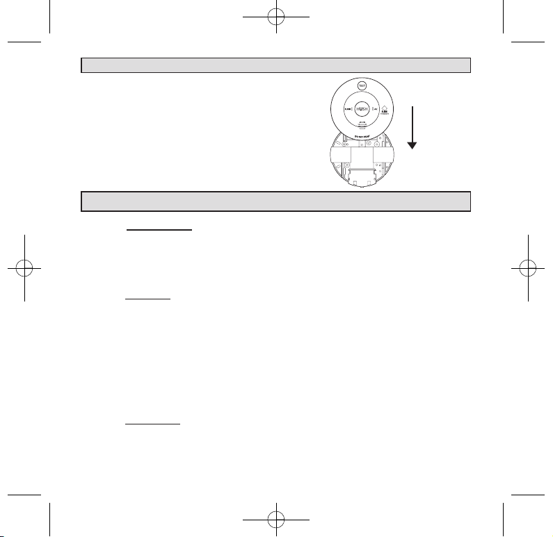
6.2.1 Separate Smoke Alarm from mounting base by sliding cover (in direction of
arrow) with one hand on the back of the mounting base and one hand sliding
Smoke Alarm(See Fig. 1).
6.2.2 Connect supply cable to terminal block and fix terminal cover.
6.2.3 Align and slide smoke alarm up onto mounting base (Fig. 2) then slide in the
reverse direction of arrow to ensure proper connection.
6.2.4 Switch on power and check the green light on alarm cover. It should be lit
when mains power is switched on indicating that the smoke alarm is properly
connected to the mounting base.
6.2.5 Secure Tamper Locking Pin (supplied) to smoke alarm.
6.2.6 Test alarm by pressing Test button.
6. INSTALLATION
1398-7210-01_v1.qxd:_ 2013.5.15 5:25 PM Page 8

99
6. INSTALLATION
Australia Patent
S/N 2008200075
Australia Patent
S/N 2008200075
Figure 1:To remove smoke alarm
Slide smoke alarm carefully
away from the base plate to
remove the smoke alarm.
Figure 2: To connect smoke alarm
1 Place smoke alarm in line with the
base plate.
2 Push smoke alarm towards connec-
tor (A). Ensure the smoke alarm
slides fully into the connector.
3 Green AC Power light will come
on when connected to mains.
A
1398-7210-01_v1.qxd:_ 2013.5.15 5:25 PM Page 9
1010
7. OPERATION, TESTING AND MAINTENANCE
7.1 Operation:
7.1.1 The smoke alarm is operational once all wires are properly connected, a fresh
battery is installed (TRFSD240PE), The smoke alarm is correctly installed
on the mounting base and the alarm has been tested.
7.1.2 There are two LED indicators. Each of them has a unique function:
7.1.3 Red LED
7.1.3.A Stand-by condition: will flash once approximately every 32 seconds to
indicate unit is functioning properly.
7.1.3.B The red LED will be on solid state when the unit goes into alarm, indicat-
ing that products of combustion have been detected. Red LED will latch
on solid state for about 5 minutes after the alarm stop. After the 5 minutes
the red LED will diminish. For interconnected units, the originating
smoke alarm Red LED will stay on. All other units will sound but Red
Led will not be on or flash.
7.1.4 Green LED
7.1.4.A AC Mains-ON Indicator: indicates that the unit is operating with AC
power. If this LED goes out, it indicates that the AC power is off.
6. INSTALLATION
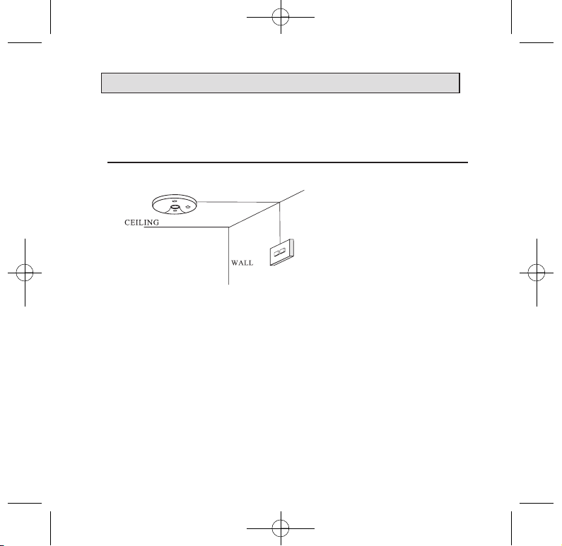
Figure 3: Wall mounting smoke alarm
For wall mounting,the connector must
be at the bottom. Ensure“ SLIDE TO
REMOVE ” arrow on the cover is
pointing upwards (vertical) as shown.
1398-7210-01_v1.qxd:_ 2013.5.15 5:25 PM Page 10
1111
7.2 False Alarm Hush Control Feature:
Note: Dense smoke will override Hush control feature and
sound a continuous alarm.
7.2.1 This smoke alarm has the capability of being temporarily
desensitized for approximately 5 minutes.
7.2.2 The smoke alarm is desensitized by pressing the“ H U S H ”
button on the smoke alarm cover.
7.2.3 After pressing the“ H U S H ” button, the alarm will silence
immediately and “ c h i r p ”every 32 seconds for approximately 5 min-
utes to indicate the alarm is in the temporary desensitized condition.
7.2.4 The smoke alarm will automatically reactivate after approximately
5 minutes and sound the alarm if particles of combustion are still
present.
7.2.5 The “HUSH” feature may be used repeatedly until the air has
cleaned.
WARNING: Before using the alarm HUSH feature, identify
the source of smoke and be certain that a safe condition
exists.
7. OPERATION, TESTING AND MAINTENANCE
1398-7210-01_v1.qxd:_ 2013.5.15 5:25 PM Page 11
7. OPERATION, TESTING AND MAINTENANCE
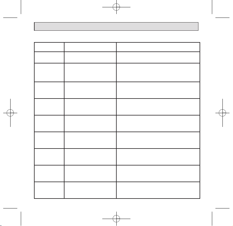
7.3 Operating and Alarm Characteristics.
Function LED Status Recommendation
Normal Green ON Green LED indicate the AC mains power is present.
Normal Red FLASHING every 40
seconds.
Red LED flashes every 30-40 seconds is normal.
The smoke alarm performs a self test every 30-40
seconds. The battery and electronics is tested for the
life of the unit.
Alarm mode
(For
TRFSD240PE)
Red light flashs. Smoke alarm
activated.
Indicate smoke alarm has activated and is in alarm mode.
The Red LED will be off after the alarm stops.
Alarm mode
(For
TRFSD240PERL)
Red light is SOLID. Smoke
alarm activated.
Indicate smoke alarm has activated and is in alarm mode.
The Red LED will latch solid for 5 minutes after the alarm
and then fade when alarm stops.
Alarm mode Red Light is OFF. Smoke alarm
activated.
Smoke alarm in full alarm. Other interconnected units
may have activated the alarm. Check other smoke
alarms or devices.
Hush mode Green light ON. Red light flash-
ing every 40 seconds.
HUSH button is pressed. Smoke alarm emits a chirp
every 40 seconds for approximately 5 minutes. Wait
5 minutes and the chirp will automatically stop.
Low Battery Green ON, Flashing red light
every 40 seconds.
Smoke alarm chirp every 40 Seconds. May indicate low
battery status. Replace the battery.
Fault
(For
TRFSD240PE)
Red light flashs.
If the red light is constantly flashs for more than
15 minutes and there is no sign of alarms. Could mean a
potential fault with the unit. Replace the alarm.
Fault
(For
TRFSD240PERL)
Red light is SOLID
If the red light is constantly solid for more than
15 minutes and there is no sign of alarms. Could mean a
potential fault with the unit. Replace the alarm.
1398-7210-01_v1.qxd:_ 2013.5.15 5:25 PM Page 12

13
8. BATTERY INSTALLATION , REPLACEMENT AND TEST
8.1 Battery Installation for TRFSD240PE
8.1.1 The smoke alarm uses one 9V battery to automatically provide back-up
power to the alarm if AC power fails. The battery will operate the alarm for
approximately one to three months with AC power off.
8.1.2 The smoke alarm has a low battery indicator that will cause the unit to chirp
and flash the Red LED at approximately 32 second intervals for a minimum of 7
days. Missing battery with main power connected will cause the unit to chirp
and flash the Red LED at approximately 32 second intervals.
8.1.3 Replace battery when chirping occurs. To ensure proper operation, the bat-
tery should be replaced once a year.
8.1.4 To replace battery, remove alarm from mounting base(see section 6.2) and
remove the battery from compartment. Replace the old battery with a new one.
8.1.5 USE ONLY THE FOLLOWING 9-VOLT
ALKALINE BATTERIES FOR
REPLACEMENT:
EVEREADY/ENERGIZER 522
DURACELL MN1604, MX1604
These batteries can be purchased
at your local retail outlet or super-
market.
Caution: Use only specified bat-
teries. Use of different battery
may have a detrimental
effect on operation or may
cause the battery to explode re-
sulting in injury or fire.
RED BATTERY LEVER
Australia Patent
S/N 2008200075
Australia Patent
S/N 2008200075
1398-7210-01_v1.qxd:_ 2013.5.15 5:25 PM Page 13
14
8. BATTERY INSTALLATION , REPLACEMENT AND TEST
8.1.6 USE ONLY BATTERIES SPECIFIED ON THE LABEL .
8.1.7 Fold Red Battery Lever down into compartment with fresh replacement
battery. If the Red Battery Lever is not held down in the battery compart-
ment by the battery, the smoke alarm will not close and will not be opera-
tional. Battery can only be inserted in one direction, ensure polarity is correct.
WARNING: Use of inferior batteries or incorrect types may cause a malfunction of the
alarm. When replacing the battery and on reconnection of the detector to the base plate,
make sure that the detector is fully connected and flush with the base plate. Verify that
the Green LED is ON after reinstalling the alarm on the base plate.
8.2 Battery Test:
8.2.1 Switch off mains power. The Green LED on the smoke alarm will be OFF.
8.2.2 Test alarm by pressing on the Test Button for a few seconds. This should sound the
alarm.
8.2.3 If the battery module has a fault, the alarm will chirp every 32 seconds.
8.2.4 Watch the Red LED for about 32 seconds. It should flash at least once.
8.2.5 Switch on mains power only when smoke alarm passes the above tests. The Green
LED on the smoke alarm will come ON.
NOTE: NO USER REPLACEABLE PARTS INSIDE.
8.2.6 For TRFSD240PERL ONLY
8.2.6.A Rechargeable battery must be checked periodically. We recommend a periodic
weekly battery test.
8.2.6.B Smoke alarm must be connected to mains power for 8 hours for the battery to be
fully charged.
8.2.6.C If the battery is weak, the Red LED will flash every 32 seconds and sound a chirp.
We recommend that you check the AC mains power and allow up to 8 hours to
fully charge the battery. If chirping continues even after sufficient charging, we
recommend you replace the smoke alarm.
8.2.6.D
The rechargeable battery will supply the alarm for at least 7 days without sound chirp
once AC power is disconnected. In normal status, the battery has life of over 10 years
1398-7210-01_v1.qxd:_ 2013.5.15 5:25 PM Page 14

15
9. 9V TERMINAL AND REMOTE TEST & HUSH
WARNING: THIS TERMINAL IS NOT ISOLATED FROM THE MAINS SUPPLY.
This first terminal (Yellow) has a 9Vdc positive output and can be used for the following
applications: As an output to operate smoke alarm as an early warning indicator system.
The 9V terminal in this smoke alarm is intended for use with a security/fire alarm
panel where a signal from that panel can be used to activate a single Smoke Alarm or
interconnected Smoke Alarms to alert residents/occupants that an alarm has been
activated elsewhere and there may be cause to evacuate the area. The diagram below
shows the 9V terminal and the Signal terminal, marked SW, connected to the N/O
(normally open) contacts of a suitable relay, the coil of which when energized from an
extra-low voltage signal from an alarm panel, closes the contacts thereby activating the
Smoke Alarm(s). This can be an Early Warning Indicator System.
Note: The presence of an audible sound from the smoke alarm and the absence of a
flashing RED LED in the smoke alarm(s), means the smoke alarm(s) have been
activated externally. It is an Early Warning Indicator.
However, check also for the presence of fire or smoke in the vicinity of your
dwellings. If there is fire, follow actions in Section 15.
It is essential that the relay and associated base must be of a type providing effective
isolation between the coil and contacts (having an isolation voltage [Dielectric
Strength] of 4kV and creep/clearance distances of no less than 8mm between the coil
and contacts). We recommend using an OMRON Relay Type G2R-2-SN and Base
Type 17X5W which meet the necessary isolation requirements.
9.1 9V TERMINAL
1398-7210-01_v1.qxd:_ 2013.5.15 5:25 PM Page 15

16
Wiring Instruction Showing Smoke Alarms Interconnected
and Used as part of an Early Warning Indicator System
9. 9V TERMINAL AND REMOTE TEST & HUSH
The use of an unsuitable relay and base could also lead to an electric shock risk.
The wiring between the Smoke Alarm and the relay must be installed in accordance
with the relevant requirements of the SAA Wiring Rules, AS3000, for low voltage
(240V) conductors.
LOOP
N
SW
A
9V
LOOP
N
SW
A
9V
LOOP
N
SW
A
9V
1224
YELLOW
RED
WHITE
BLUE
ORANGE
ORANGE
YELLOW
RED
WHITE
BLUE
FIRE INDICATOR
PANEL
LOCAL ALARM PANEL
CONNECTION TO A
MAXIMUM OF 24 SMOKE ALARMS
FUSE ON
CIRCUIT
BREAKER
See installation manual
for isolation relay RK10A/9
N
SW
9V
24V
1398-7210-01_v1.qxd:_ 2013.5.15 5:25 PM Page 16

17
9.2 REMOTE TEST & HUSH PLATE:
9. 9V TERMINAL AND REMOTE TEST & HUSH
This alarm has the ability to be connected to a Remote Test & Hush Plate(LIFTHP)
(optional accessory, sold separately). The diagram below shows a sample of the wiring
connection required for the Remote Test and Hush Plate. In order for this alarm to op-
erate properly with the LIFTHP, a Remote Test & Hush card (LIFTHC) is required for
each alarm in the interconnected system. See the owners manuals for the LIFTHP and
LIFTHC for complete operation and instructions.
THE WIRING BETWEEN TRFSD240PE AND LIFTHP
1
LOOP
9V ASW N
12
SW
LOOP
9V N
ASW
2
A
9V
LOOP
N
FUSE ON
CIRCUIT
BREAKER
1398-7210-01_v1.qxd:_ 2013.5.15 5:25 PM Page 17
18
9. 9V TERMINAL AND REMOTE TEST & HUSH
Smoke alarm with Remote Test & Hush card
Remote Test & Hush Plate
The Remote Test & Hush Plate can be mounted in an easy to reach location to
provide convenient access to the Test and Hush functions of your Models
TRFSD240I, TRFSD240PE, TRFSD240PERL smoke alarm.
Connection diagram between smoke alarm and Remote Test & Hush Plate
1398-7210-01_v1.qxd:_ 2013.5.15 5:25 PM Page 18
This manual suits for next models
1
Table of contents
Popular Smoke Alarm manuals by other brands


Visonic
Visonic SMD-429 PG2 Series Installation and operating instructions

Pyromate
Pyromate P-45 manual

Securiton
Securiton ASD 535 Application guidelines

mumbi
mumbi LM-109C user manual

Notifier
Notifier SDX-751TEM Installation and maintenance instructions

Elkron
Elkron SD610 Installation, programming and functions manual


