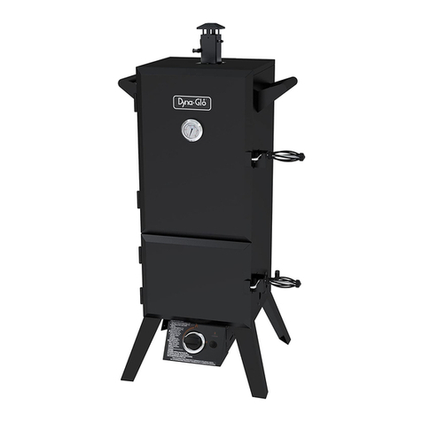
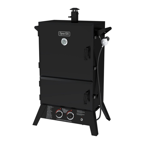
Dyna-Glo DGY784BDP User manual

MODEL #DGY784BDP/DGY784BDP-D
VERTICAL GAS SMOKER
Français p. XX
Español p. XX
Français p. 28
Español p. 55
ATTACH YOUR RECEIPT HERE
Serial Number Purchase Date
Questions, problems, missing parts? Before returning to your retailer, call our customer
service department at 1-877-447-4768, 8:00 a.m. – 4:30 p.m. CST, Monday – Friday or
email [email protected].
Rev. 07/16/19
1
70-10-541

STOP!
DYNA-GLO®VERTICAL GAS SMOKER
2

TABLE OF CONTENTS
Safety Information ......................................................................................................................... 4
Package Contents ......................................................................................................................... 7
Hardware Contents ....................................................................................................................... 8
Preparation ................................................................................................................................... 8
Assembly Instructions .................................................................................................................. 9
Operation Instructions ................................................................................................................... 14
Tips On Smoking .......................................................................................................................... 18
Care and Maintenance .................................................................................................................. 23
Troubleshooting ............................................................................................................................ 25
Warranty ....................................................................................................................................... 26
Replacement Parts List ................................................................................................................ 27
DANGER:
Failure to follow these
instructions could result
in fire, explosion, or burn
hazard which could cause
property damage, personal
injury or death.
DANGER:
If you smell gas:
1. Shut off gas to the appliance.
3. Open lid.
4. If odor continues, keep away from the appliance and
immediately call your gas supplier or your fire department.
Assembler/Installer: This instruction manual contains important information necessary for the
proper assembly and safe use of this appliance. Read and follow all warnings and instructions
before assembling and using this appliance. Leave these instructions with the consumer.
Consumer/User: Follow all warnings and instructions when using this appliance.
Keep these instructions for future reference.
1. Never operate this appliance unattended.
2. Never operate this appliance within 10 feet (3 m) of any structure, combustible material
or other gas cylinder
3. Never operate this appliance within 25 feet (7.5 m) of any flammable liquid.
4. Never allow oil or grease to get hotter than 400°F or 200°C, if the temperature exceeds
400°F (200°C) or if oil begins to smoke, immediately turn the burner or gas supply OFF.
5. Heated liquids remain at scalding temperatures long after the cooking process. Never
touch cooking appliance until liquids have cooled to 115°F (45°C) or less.
6. If a fire should occur, keep away from the appliance and immediately call your fire
department. Do not attempt to extinguish an oil or grease fire with water.
Failure to follow these instructions could result in fire, explosion, or burn
hazard which could cause property damage, personal injury or death.
DANGER
DANGER:
3

SAFETY INFORMATION
Please read and understand this entire manual before attempting to assemble, operate or install the
product. If you have any questions regarding the product, please call customer service at
1-877-447-4768, 8:00 a.m. – 4:30 p.m. CST, Monday – Friday.
• DO NOT use this product for anything other than its intended purpose. It is NOT intended for
commercial use. It is NOT intended to be installed or used in or on a recreational vehicle and/or boat.
• Keep a fire extinguisher near this product at all times.
• This appliance is for outdoor use only in well-ventilated areas. DO NOT operate it in a building,
garage or any other enclosed area, or under overhead construction.
• A minimum clearance of 36 in. (92 cm) to combustible material is required on the front, sides and back.
It is very important to always maintain proper clearances to combustibles.
• The cylinder must be at least 24 in. (61 cm) from the appliance.
• DO NOT obstruct the flow of combustion air/or ventilation air for the appliance.
• When cooking, the smoker must be on a level, stable noncombustible surface in an area clear of
combustible material, including long or dry grass.
• Care should be taken to protect the fuel supply hose from damage from either pedestrian or vehicle
traffic.
• Clean and inspect the hose before each use of the appliance. If there is evidence of abrasion, wear,
cuts or leaks, the hose must be replaced prior to the appliance being used. The replacement hose
assembly shall be that specified by the manufacturer.
• Before each use check that no dead leaves or debris are under the appliance.
• Store this appliance in a dry, protected location.
• The use of alcohol, prescription or nonprescription drugs may impair the user’s ability to properly
assemble and safely operate this appliance.
• Allow the smoker to cool to 115°F (45°C) before moving or storing. Use caution when lifting and moving
the appliance to avoid back strain or back injury. DO NOT move the appliance while it is in use.
• Always hang the regulator on the lifting handles while not in use or disconnected with the LP tank.
KEEP the fuel supply hose away from any heated surface(s).
WARNING
For more information go to www.p65Warnings.ca.gov
This product and the fuels used to operate this product (liquid propane or natural gas), and the
products of combustion of such fuels, can expose you to chemicals including benzene, which is
known tothe State of California tocause cancer or other reproductive harm.
CALIFORNIA PROPOSITION 65
4

SAFETY INFORMATION
• DO NOT store and use this appliance near gasoline or other combustible liquids or where other
combustible vapors may be present.
• DO NOT use this appliance as a heater.
• DO NOT leave the appliance unattended while in use. Keep children and pets away from the
appliance at all times.
• NEVER close the damper completely while cooking.
• If you must dispose of ashes in less time than it takes for the ashes to completely cool down, then
remove the ashes from the appliance, keeping them in the heavy-duty foil, and soak them completely
with water before disposing of them in a noncombustible container.
• This appliance will be hot during and after use. Use insulated oven mitts or gloves for protection from
hot surfaces or splatter from cooking liquids.
• Make sure that the orifice of the control valve properly mates with the burner mixing tube by
visual observation. Please refer to maintenance section.
• Use caution when opening the door of the smoker while in operation. Keep hands, face and body
safe from hot steam or flare-ups. DO NOT inhale smoke.
•DO NOT wear loose clothing while operating the smoker. Tie back long hair while operating the smoker.
ALWAYS wear shoes that fully cover your feet while operating the smoker.
• Allow the smoker and its components to cool completely before conducting any routine cleaning
or maintenance.
• NEVER use glassware, plastic or ceramic cookware on or in your smoker. Use metallic cookware only.
• NEVER operate the smoker without water in the water bowl. NEVER allow the water to completely
evaporate. Check the water level at least every 2 hours. A sizzling sound may indicate a low water
level. Follow instructions in this manual for adding water while operating (see page 15).
• When using flavoring wood, add a sufficient amount prior to operation to avoid having to add wood
while operating. Adding wood while operating may splash hot water and cause serious injury.
• Use of accessories not intended for this smoker is not recommended and may lead to injury or
property damage.
• An LP cylinder not connected for use should not be stored in the vicinity of the smoker or any other
appliance. DO NOT store spare LP cylinders within 10 ft. of the smoker. LP cylinders must be stored
outdoors, out of reach of children. DO NOT store LP cylinders in a building, garage or any other
enclosed area.
• DO NOT store LP gas cylinders inside or on top of the smoker. Improper storage of cylinders could
lead to explosion, fire and/or personal injury. Cylinders are to be stored outdoors, out of reach of
children and must not be stored in a building, garage or any other enclosed area.
• While the smoker is not in use, the gas must be turned off at the supply cylinder.
• LP gases are heavier than air, tend to pool and collect in low-lying areas, are easily ignited and are
highly flammable. Proper care and caution should be employed when dealing with any such fuels.
• The smoker should be turned off and all supply valves (on piping or on fuel cylinders) should be
closed in the event that the odor of unburned gas is detected. Do not attempt to use the appliance
until any gas leaks are fixed and/or the source of the unburned gas odor is accounted for.
5

SAFETY INFORMATION
• Do not use the smoker if the burner fails to light or fails to remain lit. Under such conditions, gas
should be turned off and the fuel cylinder should be disconnected.
•Use in high wind conditions that result in poor burner operation such as blowing out and flaring should
be avoided. If repositioning the appliance does not improve operation under such wind conditions,
the appliance should be turned off.
•Install the smoker with the hose regulator assembly extended the full length of the hose (24 in. minimum)
directly away from the appliance. When so configured, placement results in maximum tank to smoker
distance. When the smoker is operated, the hose/regulator and gas tank should be perpendicular to
wind direction. Placing tank closer than 24 in. to the smoker can overheat the tank and cause release
of propane through relief openings and can result in tank fire or explosion.
• Read and follow all warnings and instructions before assembling and using the appliance.
• Follow all warnings and instructions when using the appliance.
NOTE: The installation must confirm with local codes or, in the absence of local codes, with either
the National Fuel Gas Code, ANSI Z223.1/NFPA 54, Natural Gas and Propane Installation Code,
CSA B149.1, or Propane Storage and Handling Code, B149.2, or the Standard for Recreational
Vehicles, ANSI A 119.2/ NFPA 1192, and CSA Z240 RV Series, Recreational Vehicle Code,as
applicable.
WARNING
DO NOT mix old and new batteries.
DO NOT mix alkaline, standard (Carbon-Zinc), or rechargeable (Nickel-Cadmium) batteries.
DO NOT dispose of batteries in fire. Improper disposal may cause batteries to leak or explode.
The electronic ignition requires 1 “AAA” alkaline battery, which is included.
WARNING:
The hose to tank attachment creates a potential
trip hazard for user and pedestrians - use caution.
Do not allow or cause the gas tank or appliance
to tip.
MINIMUM 24 IN. (610 MM)
(Tank not included)
6

PACKAGE CONTENTS
PART DESCRIPTION QUANTITY
A Leg 4
B Burner & Control Unit 1
C Wood Chip Box 1
D Wood Chip Box Lid 1
E Water Bowl 1
F Cooking Grate 4
G Door Locking Bracket 2
H Smoke Stack 1
I Smoker Body 1
J Lifting Handle 2
K Side Damper 2
L
Temperature Gauge
1
M Upper Door 1
N “AAA” Battery (1.5V) 1
O Bottom Door 1
P Door Handle (Upper & Lower) 2
Q Cooking Grate Support 12
PART DESCRIPTION QUANTITY
A
B
C
D
E
F
G
H
I
J
L
M
Q
P
O
J
N
KK
P
Q
7

HARDWARE CONTENTS (shown actual size)
M6x12 Screw
Qty. 32
AA BB
Before beginning assembly of product, make sure all parts are present. Compare parts with
package contents list and hardware contents above. If any part is missing or damaged, do not
attempt to assemble the product. Contact customer service for replacement parts.
Estimated Assembly Time: 25 minutes
Tools Required for Assembly (not included): Phillips Head Screwdriver, Wrench, and Pliers.
PREPARATION
M6x12
Shoulder
Screw
Qty. 8
Spring
Clip
Qty. 2
CC DD
M6 Nut
Qty. 8
8

ASSEMBLY INSTRUCTIONS
1. Attach the legs.
Align one leg (A) with mounting holes on the
bottom of the smoker body (I). Thread screws
through holes from outside of unit. Nuts are
pre-welded to the cabinet. Repeat for other
3 legs (A). Tighten all screws (AA) with a
Phillips screwdriver.
Hardware Used
AA x12
M6x12 Screw
2. Attach the burner and control unit.
Open the bottom door of the smoker body (I).
Turn the burner and control unit (B) upside
down and place it on the bottom of the smoker
body (I), making sure the 4 mounting holes on
the burner and control unit (B) are aligned with
the holes on the smoker body (I). Note: The
control knob should be on the same side as the
door. Check that the burner is properly installed
on the orifice before attaching the burner and
control unit (B). Thread bolts (AA) through holes
from outside of unit. Securely tighten the unit
to the bottom with a Phillips screwdriver.
2
A
I
AA
B
I
AA
Hardware Used
AA x4
M6x12 Screw
1
9

ASSEMBLY INSTRUCTIONS
4. Install the cooking grate supports.
Insert the cooking grate supports (Q) into the
corresponding holes on rack of the shelf inside
the smoker body (I) from the bottom up.
NOTE: There are 8 positions to install the
cooking grate supports. The cooking grate
supports can be installed into positions
according to the need of the owner.
3. Attach the smoke stack.
CAUTION: This unit is HEAVY! Do not
attempt this step without assistance!
Close the two doors. With the assistance of
a helper, stand the unit upright on its legs on
a firm and level surface. (Make sure that the
burner/control unit and legs are attached). Open
the upper door. Position the smoke stack (H)
with control arm to the left as shown.
Attach the smoke stack (H) by using 4 screws (AA).
Securely tighten with a Phillips screwdriver.
3
H
I
Hardware Used
AA x4
M6x12 Screw
Control
arm
AA
10

ASSEMBLY INSTRUCTIONS
5. Attach the lifting handles.
Insert 4 screws (AA) through the mounting
holes on one of the lifting handles (J) and
into holes on right side of smoker body (I).
Use a Phillips screwdriver to secure the
handles to the smoker body. Repeat on left
side.
Hardware Used
5
AA x8
M6x12 Screw
I
J
6. Attach the side dampers.
Dampers (K) are installed from the inside of
smoker body (I). Thread the damper handle
through the back hole of the side damper slots.
Align the damper (K) with the mounting holes
and insert 4 screws (BB) from the outside of the
smoker body (I). Secure each bolt with nut (DD)
from the inside of the smoker body (I). Use a
Phillips screwdriver and wrench to tighten the
nuts and bolts. Do not over-tighten. Damper
must be able to slide easily from side-to-side.
Hardware Used
6
BB x8
M6x12
Shoulder Screw
I
BB
K
DD x8
M6 Nut
DD
11

Hardware Used
7. Attach the door locking brackets.
Align the door locking bracket (G) holes with
the holes on the upper right side of the smoker
body (I). Note: slots on the brackets (G) must
be facing up. Thread 2 screws (AA) through the
holes in the door locking bracket and into the
threaded holes of the smoker body (I). Tighten
the screws (AA) using a Phillips screwdriver.
Repeat on lower right side.
9. Install the wood chip box and lid.
Slide the wood chip box (C) onto the lowest
cooking grate supports inside the smoker body
(I) and put the wood chip box lid (D) on top.
7
AA x4
M6x12 Screw
I
AA
G
8. Attach the door handles.
Slide door handle (P) through brackets
in upper door. Using pliers, slide a spring clip
(CC) over the groove in the door handle as
shown. Repeat on bottom door.
Make sure both of the spring clips are securely
attached in the grooves of the handles.
8
Hardware Used
CC x2
Spring Clip
CC
P
ASSEMBLY INSTRUCTIONS
12

ASSEMBLY INSTRUCTIONS
10. Install the water bowl.
Slide the water bowl (E) onto the cooking grate
supports inside the smoker body above the
wood chip box as shown.
11. Install the cooking grates.
Slide the 4 cooking grates (F) onto the top
cooking grate supports inside the smoker
body (I).
12. Mount the temperature gauge assembly.
Insert the probe of the temperature
gauge (L) through the middle hole of the
smoker door from the outside. Secure
with pre-assembled nut from inside
panel using wrench.
12 L
13

ASSEMBLY INSTRUCTIONS
CONNECTING THE LP TANK
WARNING! ALL INSTRUCTIONS AND SAFEGUARDS ON THIS PAGE MUST BE FOLLOWED
TO PREVENT FIRE, DAMAGE AND/OR INJURY.
1. The knob on the LP tank must be closed. Make sure that the knob is turned clockwise
to a full stop. The cylinder supply system must be arranged for vapor withdrawal.
2. Check that the control knob on the control unit is turned off.
3. Remove the protective cap from the LP tank valve and coupling nut.
4. Hold the regulator in one hand and insert the nipple into the valve outlet. Be sure the nipple
is centered in the valve outlet. The coupling connects to the large outside threads on the
valve outlet. Use care – do not cross thread the connection.
5. Hand tighten the coupling clockwise until it comes to a full stop. Firmly tighten by hand only.
Do not use tools.
Straight
CAUTION: In the connection
process, make sure the regulator
inlet connector mates with the
cylinder valve outlet properly,
safely and firmly.
13. To install the “AAA” battery (N), remove the
igniter button by turning it counterclockwise
and inserting the “AAA” battery (N) with the
positive end facing out. Reinstall the ingniter
button by turning it clockwise and hand
tightening.
13
N
OPERATION INSTRUCTIONS
14

REPLACEMENT PARTS LIST
For replacement parts, call our customer service department at 1-877-447-4768, 8:00 a.m. – 4:30 p.m.
CST, Monday – Friday.
Printed in China
PART DESCRIPTION PART #
1 Leg 301-01016-00
2 Burner and Control Unit - includes 312-11015-00
burner box, cast iron burner, burner
support bracket, LP gas hose and
regulator assembly, control panel,
knob bezel.
3 Wood Chip Box 301-01028-00
4 Wood Chip Box Handle Only OR 301-01029-02
Wood Chip Box Lid Handle Only
5 Wood Chip Box Lid (without handle) 301-01029-00
6 Water Bowl 301-02017-00
7 Cooking Grate (5/4 mm dia) 301-01014-00
8 Door Locking Bracket 302-01008-00
9 Lifting Handle 301-01010-00
10 Cooking Grate support 302-01030-00
11 Smoke Stack 312-02009-00
70-10-541
PART DESCRIPTION PART #
12 Smoker Body 70-01-321
13 Temperature Gauge and Nut 211-02005
14 Logo Plate----Dyna-Glo 211-02002
15 Upper Door 304-02002-00
16 Bottom Door 302-02102-00
17 Door Handle Crank 302-02007-02
18 Door Handle Grip 302-02007-01
19 Side Damper Plate (with handle) 312-01001-06
20 Igniter Ground Wire 301-01015-08
21 Ignition Cap Spring only 301-01015-05
22 Electronic Ignitor with cap 301-01015-06
23 Push Button Cap only 301-01015-03
24 Control Knob 301-01015-01
25 Igniter Electrode and Ignition Wire 301-01015-07
N/A Hardware Bag 312-12026-00
N/A Owner’s/Instruction Manual 70-10-541
1
13
25
3
6
4
8
10
2
15
16
12
7
17
5
24
20
23
19
11
14
18
9
21
22
27
Other manuals for DGY784BDP
1
This manual suits for next models
1
Table of contents
Other Dyna-Glo Smoke Alarm manuals
Popular Smoke Alarm manuals by other brands

UTC Fire and Security
UTC Fire and Security Edwards Genesis WG4RF-SVMC Installation sheet

Kidde
Kidde 29J user guide

Ecodhome
Ecodhome 01335-2010-00 installation manual

DSC
DSC Meridian WLS906-433 Instructions for installation and use

AJAX
AJAX FireProtect user manual

Vision
Vision ZS 6101 EU Installation & operation manual