Pyromate P-45 Firing System
Page 3 of 9
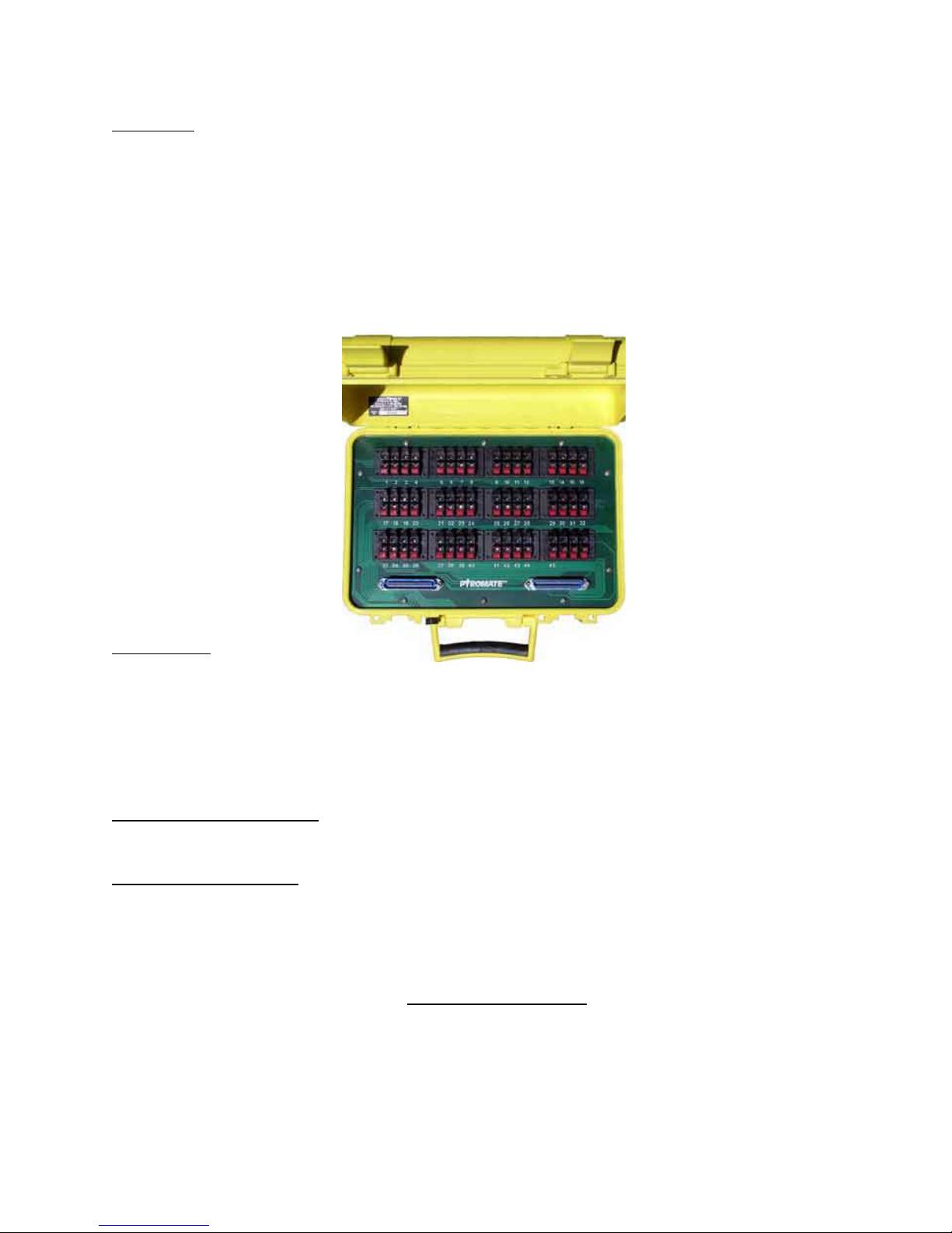
Control Panel
The Panel CONTROLS consist of the following:
Power Switch – This toggle s itch, labeled ON OFF controls the po er of the control panel. When the
po er is on, the ON indicator LED ill light and any igniters attached to selected firing module is be
sho n by the associated continuity LED.
Firing switch 1 thru 45 – These 45 momentary toggle s itches control po er to the associated terminal
connections on the selected firing module. The s itch ill only apply the po er to the terminal hile
the ARM keys itch is turned to ARM (clock ise horizontal position). To fire igniter attached to the
associated terminal connectors of the selected firing module, the appropriate s itch is moved up ard
momentarily and then released. The continuity LED of the terminal position ill go out hile the s itch
is held in the activated position, but may relight hen the s itch is released.
Arm KEYSWITCH – This keys itch controls the firing operation of the firing toggle s itches by applying
or interrupting po er to firing s itch. The vertical position (s itch rotated counter-clock ise) is the
SAFE position here po er is interrupted to the firing s itches. The horizontal position (s itch rotated
clock ise) is the ARM position and also is indicated by the ARM LED being lighted.
Ban Select Rotary Switch (A-L) – Each firing module that is attached to the control panel is accessed by
rotating the Bank Selector to the associated Selector letter A thru L. Each letter on the rotary s itch
refers to the similarly lettered DB15 connector at the top of the control panel. When a cable and firing
module is attached to the selected connector, a pin on the firing module can be activated (fired) by
pressing the desired firing s itch on the control panel.
The INDICATORS consist of:
Charge Status LED –This LED located by the charging jack sho s the status of the battery as it is being
charged. The LED is off hen no charger is connected. When the correct charger is plugged into the
charging jack, the LED ill be RED if the internal battery is charging or GREEN if the internal battery is
fully charged.
Power ON LED – This status LED located Right of the ON legend in the upper left corner of the control
panel indicates that the ON-OFF s itch is set to ON and that the internal battery does have some po er.
If this LED doesn’t turn on hen the ON s itch is set ON, the internal battery is completely discharged
and ill need to be replaced.
Continuity 1 thru 45 LEDs – These status LEDs located above each of the 45 firing toggle s itches sho
the presence of a electrical connection (igniter) attached to the selected firing module hen the control
panel is ON. Each of the continuity LEDs ill conduct 20 milliamps of current thru the connected device.