Tradgardsteknik TMT30 Manual
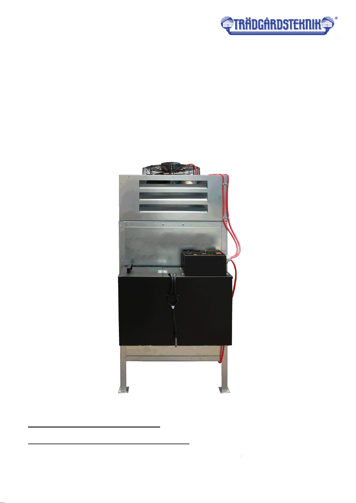
HEATER FOR UNIVERSAL OIL
TYPE
INSTALLATION AND
MAINTENANCE MANUAL

1. Purpose
The universal oil heater is intended for heating industrial premise is not covered by the central
heating system (workshops, car services, industrial halls, warehouses, livestock buildings, basements, garages,
etc.). The furnace can operate on most waste oils, e.g. engine oil, gear oil, hydraulic oil, diesel oil, HBO I, II and III
type oils with a viscosity not higher than SAE 80.
DO NOT USE TRANSFORMER OILS
THEY MAY CONTAIN SUBSTANCES HARMFUL TO THE OPERATION OF THE MACHINE
TECHNICAL DATA
Maximum capacity *
kW
30
Minimum capacity*
kW
8
Max oil consumption
l/h
3,0
Min oil consumption
l/h
0,8
Heated air flow
m³/h
1460
Electrical supply
V/Hz
230/50
Max power consumption
W
100
Exhaust outlet diameter
mm
130
Width
mm
920
Height
mm
1350
Length
mm
540
Weight
kg
50
* Thermal efficiency given for fuel with the following parameters:
● heating value = 42,6 MJ/kg.
● density at 15°C max. = 860 kg/cm³. MODEL OF THE NAMEPLATE ON THE BACK OF
DEVICE, ON THE COVER
With higher parameters, the thermal efficiency may increase up to 33 kW
2. Environmental conditions of storage
The 8 -30 universal oil heater should be stored in the following conditions:
• temperature -20..85°C
• relative humidity 5..85%
• pressure 800..1200 hPa
• no dust
• environment free from the chemical contamination.
3. Environmental conditions of use
The 8 -30 universal oil heater should be used in the following conditions:
• temperature 0..30°C
•relative humidity 5..85%
• pressure 800..1200 hPa
• degree of protection against environmental influences IP65
• good ventilation of the heated space
4. Characteristic features of the controller
• three-stage power regulation of the furnace 8-19-30 kW,
• preservation of settings in the event of a power supply failure.
5. Security aspects
The 8-30 universal oil heater is powered by an alternating current network of 230V / 50Hz. It is
equipped with three sensors ensuring safe and economical operation of the device.
1. The bimetallic sensor, located at the furnace chamber, reacts by shorting the points in the thermostat
when the temperature exceeds 40°C and opening the points when the temperature drops below 35°C.
2. The bimetallic sensor, located near the supply fan, whose threshold temperature is 100°C, opens the
points when this temperature is exceeded and causes the heater to go into emergency mode, disconnecting the
fuel supply, thus protecting the fan against overheating or melting of its elements.
3. Micro-switch, weight sensor located under the combustion chamber. Filling the bowl causes the heater
to go into emergency mode immediately, disconnecting the fuel supply. This prevents it from spilling out excess
non-vaporized fuel outside the combustion chamber, eliminating the possibility of its ignition outside the device.
Connection of the heater control panel with other system components (sensors, pump, fan) is made at the
factory and during normal operation, for safety reasons, it is not allowed to interfere with the covered and
sealed part of the heater controller and to violate the integrity of the wires. Any action of an unauthorized
person may result in electric shock (230V AC, 50Hz) and burns
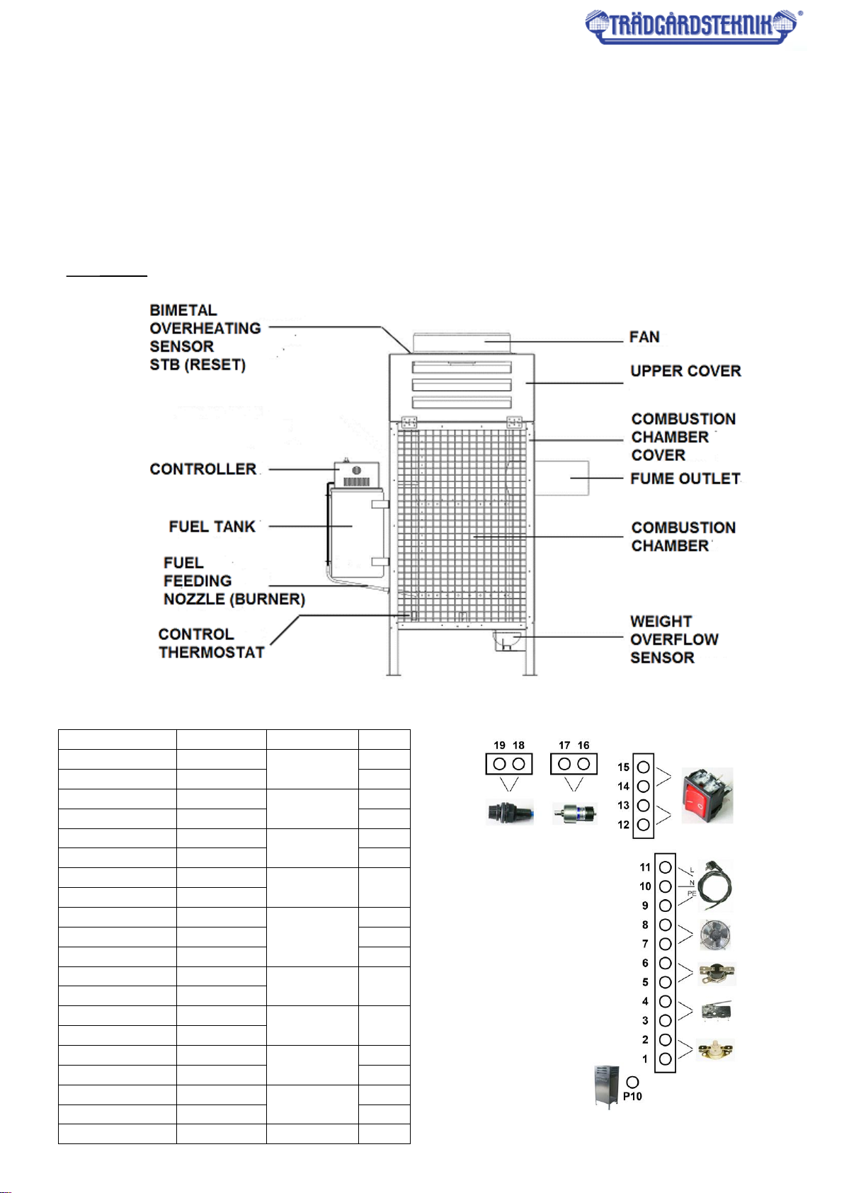
6. structure
Fig. 1. heater structure
Fig. 2. heater controller scheme.
Exit Description Info
1 STB Thermostat
STB
2 STB
3 OVL Bowl
4 OVL
5 T_STER Control
thermostat
6 T_STER
7 WENT Fan output 230V
8 WENT
9 POWER Power
supply
P
10 POWER N
11 POWER L
12 SW1A Power
switch
Para
A
13 SW1A
14 SW1B Power
switch
Para
B
15 SW1B
16 PUMP Fuel
pump
+
17 PUMP -
18 BZ1 External
fuse
19 BZ1
P10 Obudowa
7. Assembly
-check all local regulations,
-place the heater on a flat and hard surface,
-level the device,
-to ensure optimal chimney draft, install at least five meters long, smooth, heat-resistant, vertical
chimney pipe (not aluminum), preferably made of acid-resistant steel,
-check the tightness of all connections, if necessary, seal them with insulating tape,
-make sure that the elements inside the combustion chamber are correctly placed and the burner is
pushed all the way in,
-- check the mains voltage (220-240V / 50Hz) by connecting the heater to the mains and by switching the
0/1 switch,
-- check if in position 1 the switch is red.
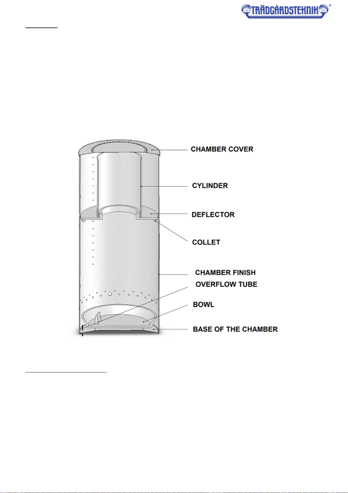
Fig. 3. Structure and components of the combustion chamber
7a. Installation of the chimney
A properly constructed chimney installation is necessary to ensure proper combustion.
When performing it, follow the recommendations below:
- the diameter of the exhaust outlet from the device is 130 mm,
- the recommended diameter of the chimney pipe is 130 - 150 mm,
- the minimum height of the chimney with a diameter of 150 mm is 5 meters,
- check the tightness of connections between the chimney elements,
- the wind should freely blow the chimney outlet from all directions - the end of the chimney pipe should be
approx. 1 m above the top of the roof,
- if possible, all sections of the chimney should be vertical - avoid horizontal sections, as well as bends of the
chimney pipe - if bends are necessary (e.g. two bends in the case of leading the pipe through a wall or window)
then the maximum bend angle must not exceed 45°, and the minimum height of the chimney should be
increased to 6 meters.

ATTENTION
When installing the flue gas discharge system, it is recommended to avoid horizontal sections of the chimney
pipe.
In order to ensure free outflow of gases, the angle of possible bending of the pipe should not be greater / less
than 45°. The chimney outlet must be higher than the top of the roof, preferably approx. 1 m.
The places where the chimney passes through the ceiling, walls or roof must be insulated to avoid fire
hazards. It is recommended to use a double-layer insulated chimney pipe wherever there is a possibility of
touch contact and outside the building to ensure constant good draft and prevent condensation. Do not place
any materials near the heater, even non-flammable ones.
Constant access of air necessary for the proper combustion process must be ensured.
Fig. 4. Chimney installation
8. Description of device operation
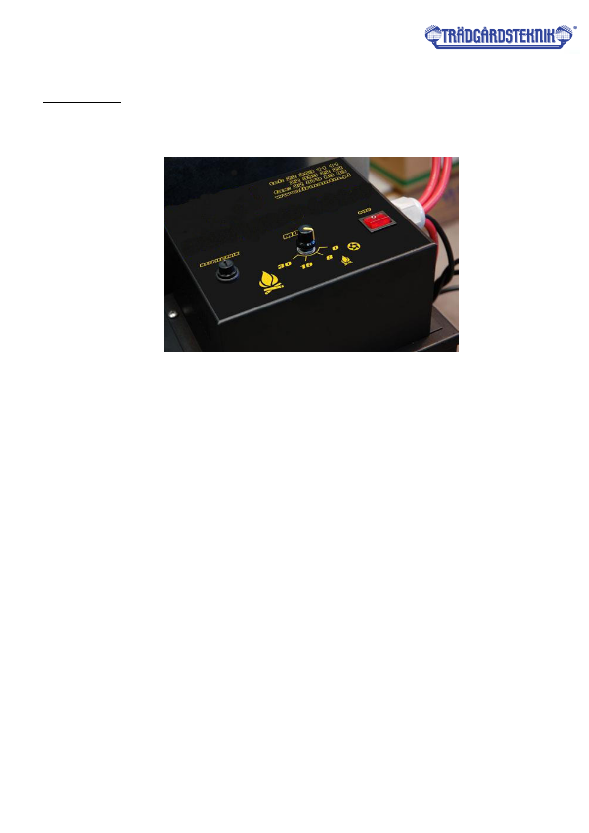
8a. Control panel
The universal oil heater controller type is equipped with a power setting knob, a mains switch,
and a fuse socket.
.
Fig. 5. View of the front control panel.
8b. The operation of the device is characterized by the following states:
•Stop device is ready to start
•Firing up the initial phase of device operation
•Activity proper operation of the device
•Stopping turning off the device
•Overheating emergency shutdown
•Tank overflow emergency shutdown
The process of generating heat is carried out by burning gas, which is produced by oil heated to high
temperatures. When the device is connected to the mains, it is in standby (Stop) mode and no heat is produced,
neither the fan nor the pump is running.
Pressing the button marked NETWORK in position 1 causes the heater to be ready for firing up (you can
see firing up at point 9a). After firing up and heating the heater to a temperature of approx. 40 ° C, the oil
feeding pump, and the supply fan are turned on.
Due to the lower demand for oil when the furnace is not heated, the device should operate at 19kW for
at least 15 minutes. After approx. 15 minutes of operation, when the furnace bowl is sufficiently warmed up and
is able to evaporate a larger amount of oil, the power of the device can be switched to 30 kW or less 8kW. When
working at the highest power, approx. 3 liters of oil is fed to the furnace.
The heater is turned off by pressing the button marked NETWORK in position "0" on the control panel. At
this point, the pump is turned off. The supply fan works until the furnace temperature drops below approx. 35°C
(Stopping). After reaching a lower temperature than 35°C, the stove returns to the Stop phase.
The heater can be turned off automatically in the following cases:
- overheating of the combustion chamber,
- overflows.
The overheating condition is generated by a bimetallic sensor located near the fan. The opening of the
contacts signals that the threshold temperature value has been exceeded. The control system turns off the fuel

feeding pump and the fan works until the furnace temperature drops below 35°C. Upon reaching a temperature
lower than 35°C, the furnace returns to the Stop phase.
To return to normal operation, wait until the furnace cools down (turning off the fan and cooling down the
chamber) and press the button on the bimetallic sensor housing (reset). Clean the furnace bowl, taking into
account that the bowl and the deflector may still be hot due to the fact that cast iron maintains the temperature
for a long time. The heater can then be restarted as described in point 9a.
The overflow signal is generated by a mechanical sensor located under the overflow tank. The opening of
the contacts signals that the tank is overfilled and turns off the fuel feeding pump, and the fan works until the
furnace temperature drops below 35°C. Upon reaching a temperature lower than 35°C, the furnace returns to
the Stop phase.
To return to normal operation, wait until the heater has cooled down (the fan is turned off and the
chamber has cooled down), empty the overflow tank, clean the furnace bowl and the combustion chamber,
taking into account that the bowl and deflector may still be hot because cast iron maintains the temperature for
a long time. The heater can then be restarted as described in point 9a.
9. Heater service
ATTENTION!!!
DO NOT ADD OIL TO THE FURNACE AND LIGHT WHILE THE FURNACE CHAMBER OR
BOWL IS STILL HOT !!!
ALWAYS WAIT FOR THE FURNACE PLATE TO COOL DOWN COMPLETELY.
IF YOU DO NOT FOLLOW THE ABOVE RECOMMENDATION, YOU MAY CAUSE
UNCONTROLLED IGNITION OF OIL FUMES AND BURN!!!
9a. Starting the device.
-if necessary, drain the water from the fuel tank and fill it with oil (e.g. used oil),
-check the correct operation of the overflow protection mechanism by weighing the cup lever
downwards and its spontaneous return, confirmed by a characteristic sound "click",
-check if the burner of the device is pushed as far as possible to the cover of the device (if it is not, it
should be pushed in),
-insert the plug of the power cord into the mains socket (230V / 50Hz),
-tilt the upper part of the heater cover and remove the combustion chamber cover, then remove the
cylinder and deflector (if necessary, thoroughly clean the combustion bowl and the base on which it is
placed, as well as the entire combustion chamber with the sleeve and deflector),
-verify if the furnace bowl is cool and clean, then pour about 250 ml of heating oil or diesel fuel into it,
-assemble the ring and cylinder,
-light the oil using a piece of paper crushed into a ball, set it on fire, and then throw it on the hearth bowl,
-put on the combustion chamber cover, close the upper part of the heater cover,
-press the button marked as NETWORK to position 1 and turn the knob of the power setting to the
position 19 kW.
-after approx. 10-15 minutes, depending on the room temperature, the fuel pump and the fan are turned
on. The heater must run at this power for a minimum of 15 minutes. After approx. 15 minutes of
operation, when the furnace bowl is sufficiently warmed up and is able to evaporate a larger amount of
oil, you can switch the power of the device to 30 kW or reduce it to 8kW .

9b. Shutting down the device
To turn off the device and end the heating process, on the control panel turn the power setting knob to
the fan position and switch the button marked as NETWORK to position 0, which will turn off the lamp. The
pump will stop feeding fuel to the combustion bowl, and the fan will continue to run until the heater cools
down. The extinguishing process depends on the room temperature and the degree of heating of the
combustion chamber and may last from 20 to 40 minutes.
DO NOT disconnect the device from the power supply when the fan is running! Wait for the heater to cool
down. The heater is turned off automatically. It should be remembered that after the device is turned off, the
cast iron bowl maintains a higher temperature for some time (depending on the ambient temperature) and
the heater cannot be re-ignited until the bowl is completely cold!
DO NOT throw a hot bowl into the snow, or pour cold water over it to accelerate cooling - a hot bowl, due to a
large temperature difference, will crack and will be unusable !!!
9c. Maintenance
The heater requires very little maintenance. Following the manufacturer's recommendations in this regard will
ensure failure-free and safe operation of the device:
-clean the furnace bowl and other elements of the combustion chamber (cylinder, deflector, and cover)
daily,
-check the overflow pipe for blockage (the pipe in the lower part of the combustion chamber, directly
above the overflow bowl), clean if necessary,
-at least once a week clean the base of the combustion chamber (the element under the furnace bowl),
-check that the air inlet openings in the lower and upper parts of the combustion chamber are not
blocked,
-clean the fuel feeding pipe (burner) at least once a week, the maximum working time without cleaning
the furnace bowl is approx. 7-14 hours. (depending on the combustion oil used),
-during the heating season, clean the fuel tank and the oil pump filter,
-if the heater will be off for a longer period, carefully clean the combustion chamber and the day tank,
then protect them against corrosion by coating them with a thin layer of oil.
SEASONAL INSPECTIONS ARE RECOMMENDED
AT THE AUTHORIZED SERVICE
10. Fault repair
In the event of a device failure, the list below may help you locate the fault. Generally, they are easy to remove.
Possible problems are listed below. The numbers indicate possible causes. The order of the digits shows the
probability of a failure.
ATTENTION:
Before beginning any activities, disconnect the plug from the socket.
PROBLEM CAUSE
Pump does not start 6-3-7
The flame goes out and the pump continues to run 2-5-9-10-12
The combustion chamber rumbles. 10-11-12
Soot appears in the combustion chamber and in the chimney. 8-9-10-11-12

Unburned oil remains on the combustion plate. 8-9-11-1 or too much petrol when
starting.
Lp.
CAUSE
SOLUTION
1
There is no electrical power.
Check if the plug is in the socket and check the
fuses
2
Water or sediment in the tank.
Clean the tank and filter
3
The pump motor does not start
Check the STB and overflow protection
4
Motor and pump are not working
The fuel is too thick or too cold.
Dilute with diesel fuel.
Check the pump operation control thermostat and
replace if necessary.
Check the motor and see if the pump it is not dirty
inside.
Check the STB and overflow protection
5
The fuel line is clogged, oil is returning to the
tank through the return line
Clean fuel line or replace if necessary
6
The pump operation control thermostat has
not reached the correct temperature
Allow the heater to cool down and restart it
Replace the thermostat
7
The overflow protection is full
Clean
8
The safety thermostat (STB) is not working
properly or is not working at all.
Reset the thermostat
Replace
9
Insufficient combustion air supply
Clean the combustion chamber openings
Check the proper operation of the fan
10
Incorrect air draft
Check if the chimney pipe is installed in accordance
with the recommendations in point 7a
Check the tightness of the chimney system
Clean if necessary
11
The chimney draft is too strong or too
fluctuating
Install the draft stabilizer and adjust it for min. 2
mm W.C. (19,6Pa).
12
The chimney draft is too weak
Check all connections
Reduce the number of bends
Extend the chimney
Insulate the chimney pipe outside the building
Review all information on the flue in the Manual
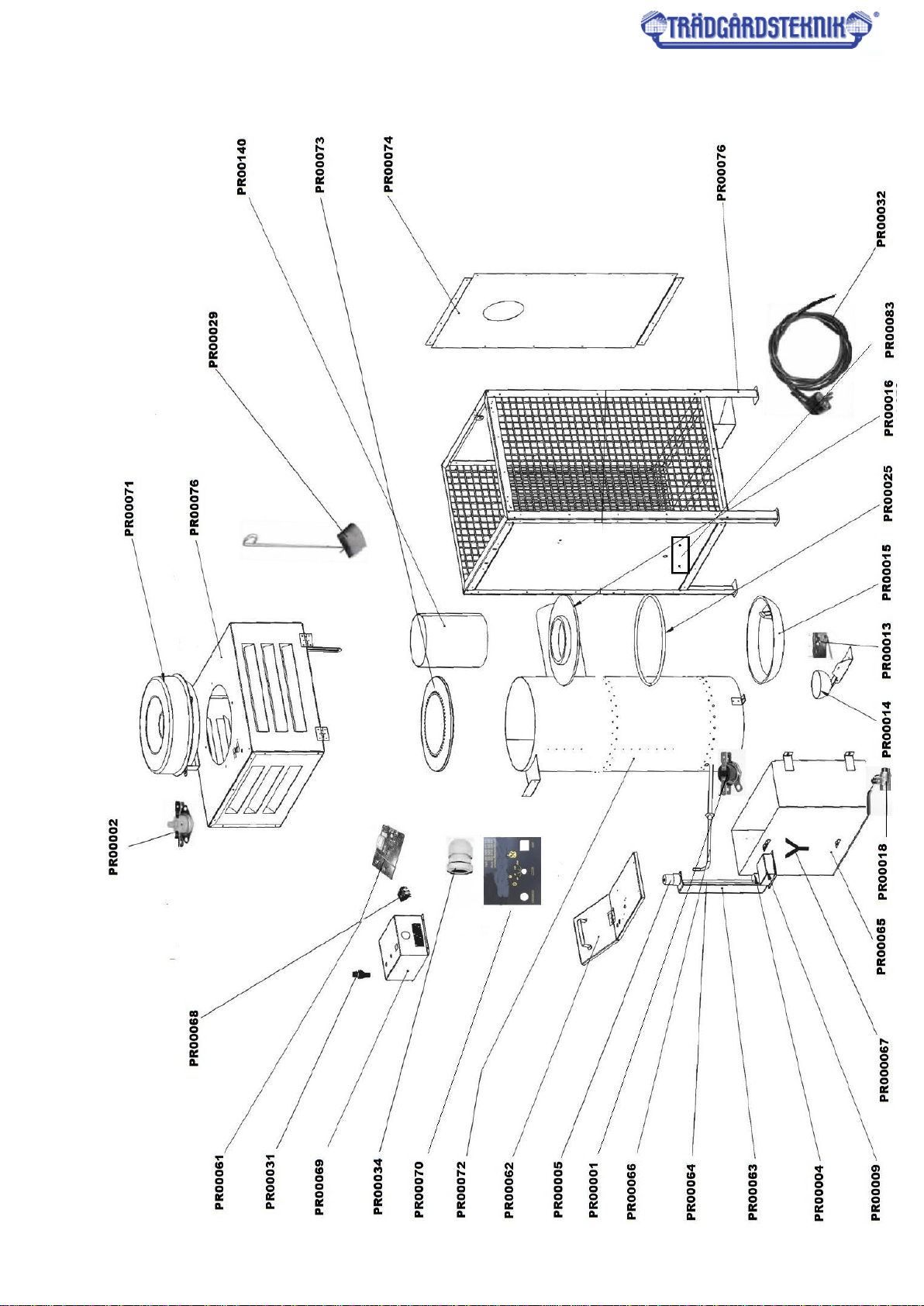
Service parts diagram

List of parts
PR00001 - CONTROL THERMOSTAT (T40)
PR00002 - STB THERMOSTAT (T100)
PR00004 - FUEL PUMP
PR00005 - FUEL PUMP MOTOR
PR00009 - FUEL PUMP FILTER
PR00013 - OVERFLOW MICRO SWITCH
PR00014 - OVERFLOW SECURITY - SET
PR00015 - CAST IRON BOWL
PR00016 - CAST IRON DEFLECTOR OF COMBUSTION CHAMBER
PR00018 - FUEL TANK DRAIN VALVE
PR00025 - COMBUSTION CHAMBER RING
PR00029 - BURNER FOR CLEANING THE COMBUSTION CHAMBER
PR00031 - FUSE SEAT
PR00032 - 230V POWER CABLE WITH A PLUG
PR00034 - LARGE CABLE GLAND
PR00061 - CONTROLLER ELECTRONIC BOARD
PR00062 - FUEL TANK COVER
PR00063 - FUEL PUMP BRACKET
PR00064 - FUEL PUMP DRIVE SHAFT
PR00065 - FUEL TANK
PR00066 - FEED PIPE TO COMBUSTION CHAMBER
PR00067 - TEE FOR FUEL LINES
PR00068 - FURNACE SWITCH
PR00069 - CONTROLLER COVER
PR00070 - DRIVER STICKER
PR00071 - 250mm AXIAL FAN
PR00072 - COMBUSTION CHAMBER
PR00073 - COMBUSTION CHAMBER COVER
PR00074 - REAR COVER OF COMBUSTION CHAMBER
PR00076 - STOVE CONSTRUCTION INCLUDING FAN CASING
PR00083 - BLANKING FOR CONTROL THERMOSTAT
PR00140 - COMBUSTION CHAMBER CYLINDER
Table of contents
Other Tradgardsteknik Heater manuals

Popular Heater manuals by other brands

Technotherm
Technotherm TT-KS 500 S X4 Installation and technical manual

Desa
Desa BLP55VA owner's manual

Harvia
Harvia HL16U1 Owner's/operator's manual

Roca
Roca NC 3000 Operating, cleaning and maintenance instructions for the user

Modine Manufacturing
Modine Manufacturing IHR 60 Installation and service manual

THE RADIATOR COMPANY
THE RADIATOR COMPANY Echo Fitting instructions


