Traffic Logix SafePace 500 User manual

TRAFFIC LOGIX®
SAFEPACE® 500 INSTALLATION MANUAL
Radar Sign Installation
Copyright © 2011-2018 Traffic Logix Corporation All rights reserved.

SafePace® 500 Installation Manual
Copyright © 2011-2018 Traffic Logix Corporation. All rights reserved.
This manual may not be copied in whole or in part, nor transferred to any other media or language, without the express
written consent of Traffic Logix Corporation.
This document is supplied as a guide for the SafePace 500 product. Reasonable care has been taken in preparing the
information it contains. However, it is possible that this document contains omissions, technical inaccuracies, or
typographical errors. Product specifications are subject to change without notice and should not be considered
commitments by Traffic Logix Corporation. Traffic Logix Corporation does not accept responsibility of any kind for
customers’ losses due to the use of this document.
Trademarks
Traffic Logix® and SafePace® are registered trademarks of Logix ITS Inc. All other product and company names are
trademarks or registered trademarks of their respective owners.
This document may contain confidential and proprietary information of Traffic Logix Corporation and/or other third
parties which is protected by copyright, trade secret and trademark law and may not be provided or otherwise made
available without prior written authorization.
Document created: 9:52 AM on Wednesday, September 5, 2018
Document version: 3.4
Traffic Logix Corporation
3 Harriet Lane
Spring Valley, NY
USA 10977
Tel: 1 (866) 915-6449
Fax: 1 (866) 995-6449
Web: www.trafficlogix.com
Email: info@trafficlogix.com
SafePace® 500 Installation Manual p. 2

TABLE OF CONTENTS
Chapter 1 4
Introduction 4
Overview 5
About this Manual 6
Documentation Conventions 6
Using Additional Customer Resources 7
Online Customer Area 7
Contacting Technical Support 7
Chapter 2 8
Installing the SafePace 500 8
Selecting a Site for the Sign 9
Choosing a Position for the Sign 10
Installing the Waterproof Breathers 11
Using Pole Banding Mounting 12
Chapter 3 14
Power Options for your Sign 14
AC Power 15
Solar Power 16
Mounting the Solar Panel 16
Installing the Batteries 17
Charging the Batteries 18
Wiring the Solar Panel to the Sign 19
Chapter 4 21
Sign Operation and Maintenance 21
Opening and Closing the Sign Latches 22
Operating Your Sign 24
Turning the Sign On and Off 24
Replacing Key Components 26
Warranty 27
SafePace® 500 Installation Manual p. 3

Chapter 1
INTRODUCTION
SafePace® 500 Installation Manual p. 4

Overview
Overview
The SafePace 500 variable speed limit sign offers the flexibility to display speed limits based on work or
school zone scheduling. This speed limit solution doesn't compromise on digit size or visibility. Using highly
visible LEDs, it displays the speed limit in full 15-inch digits that can be seen from up to 600 feet away. This
ensures that motorists are aware when the speed limit has changed. With a built-in strobe and flashing digits
to warn violators, the SafePace 500 is ideal for use anywhere that speed limits vary by time of day or week.
The SafePace 500 variable speed limit sign can also be combined with the SafePace® Beacons to create a
complete School Zone System, and can be mounted to the SafePace® Cruiser or Cruiser LT for portable
speed control. For more information about these configurations, please visit the documentation section in
the customer downloads area of our Traffic Logix® website for more information.
SafePace® 500 Installation Manual p. 5

About this Manual
About this Manual
This manual describes the installation of the SafePace 500 sign, along with an optional solar panel, to the
side of a pole. This manual also describes the wiring specifications for AC powered, and combined
solar/battery powered configurations.
Documentation Conventions
This document uses the following formatting conventions:
Format Description
Bold Gray Used in procedures to indicate menu commands, interface controls
and dialog box options.
Italics Used to place emphasis on certain words.
Monospace text Used for code samples and any information that the user enters.
Italicized
monospace text
Used to indicate text that you should replace with your own. For
example: In the Save As text box, enter c:\filename.ext where
filename.ext is the name of the file you want to save.
> Used to indicate a sequence of commands (and sub commands) to be
carried out in the displayed order. For example File > Exit means to
open the File menu then choose the Exit command. This applies to
menus from the main menu bar, context menus that appear when you
right-click on the interface, and tiles in a tiled interface.
NOTE: Notes are used as reminders or to provide information of interest that supplements or
emphasizes important points of the main text.
TIP: Tips are used to suggest alternative methods, workarounds and/or shortcuts that are not essential
but that you may find useful in a given situation.
CAUTION: Cautions are used to advise users of specific actions that could result in a loss of data.
WARNING: Warnings are used to advise users of specific actions that could result in personal physical
injury or damage to equipment.
SafePace® 500 Installation Manual p. 6

Using Additional Customer Resources
Using Additional Customer Resources
The following topics give you more information about additional resources available to our customers:
»Online Customer Area below
»Contacting Technical Support below
Online Customer Area
Visit the Online Customer Area at (https://trafficlogix.com/customer-area/) to gain access to a range of
resources including product documentation, software downloads and support videos, that will allow you to
get up to speed with your Traffic Logix product.
NOTE: The Customer Area is password protected so you may need to apply for a password if you
haven't already obtained one.
Software Downloads
Provides convenient access to the latest versions of our software applications and utilities.
Support Videos
Provides access to several videos that can help you get up to speed with your Traffic Logix product.
Product Documentation
Provides access to the most recent versions of our product documentation. If you are unable to access our
online documentation, please contact our Technical Support Department to discuss alternatives.
Contacting Technical Support
If you have questions or comments regarding this document or SafePace 500, please feel free to contact
our technical support center by phone: 1 (866) 915-6449, or by email: support@trafficlogix.com
SafePace® 500 Installation Manual p. 7

Chapter 2
INSTALLING THE SAFEPACE 500
SafePace® 500 Installation Manual p. 8

Selecting a Site for the Sign
Selecting a Site for the Sign
The site you select for the sign may vary with the application in which the SafePace 500 radar sign is being
used. However, you should generally adhere to the following guidelines:
»Choose a location where the line of sight from the radar sign to the vehicle will be uninterrupted. Give
consideration to how the location may develop with time. The following types of questions should be
considered:
•Will any trees grow directly in the line of vision?
•Is it likely that road traffic signs will be erected in a position that could obstruct the field of view?
•For solar-powered signs, are the solar panels likely to be blocked by any trees or other structures?
»Install the radar sign directly adjacent to the lane of traffic being targeted since an interfering lane of
traffic may cause inaccurate speed readings.
»Mount the radar sign to a stable and firm structure. Avoid structures that are likely to be affected by
wind or rain. We suggest that you use a 4-inch to 5-inch diameter circular metallic pole, ideally, or a 4-
inch × 4-inch wooden pole. .
SafePace® 500 Installation Manual p. 9
Choosing a Position for the Sign
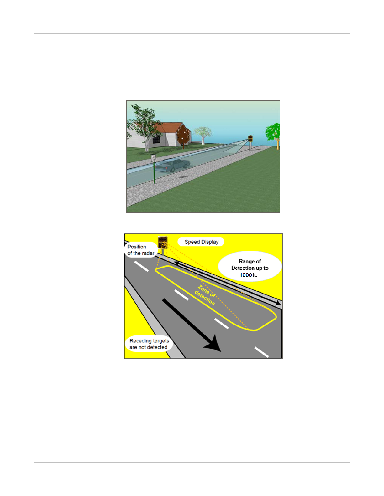
Choosing a Position for the Sign
Similar to other road signs, the SafePace 500 radar sign should be installed near the closest lane of traffic,
although off the actual road. The recommended height of the lower edge of the radar speed sign is
approximately 7 feet above the surface of the road. The display should be turned towards oncoming traffic
so that it is clearly visible to approaching drivers.
Figure 1: Example of Sign Location
Figure 2: Zone of Detection
SafePace® 500 Installation Manual p. 10
Installing the Waterproof Breathers
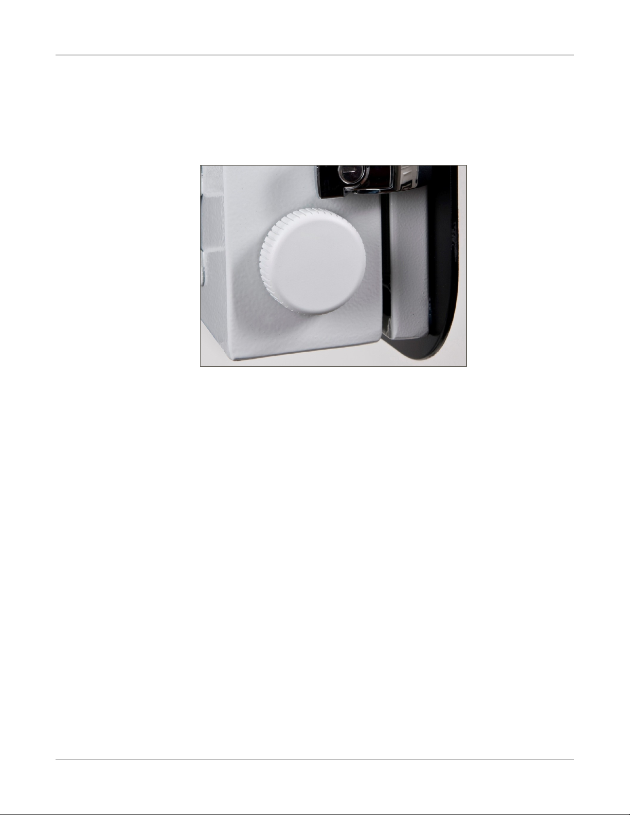
Installing the Waterproof Breathers
The SafePace 500 radar signs come almost fully assembled. To prevent breakage during shipping, the two
waterproof breathers which are mounted diagonally on either side of the sign are shipped uninstalled inside
of the sign. These breathers allow only airflow, not moisture, to circulate throughout the sign which
prevents condensation and overheating.
Figure 3: Waterproof Breather
To install the waterproof breathers:
1. Remove the breathers from their shipping bag.
2. Insert them into the pre-cut mounting holes and secure them with the supplied rubber washer and nut.
SafePace® 500 Installation Manual p. 11

Using Pole Banding Mounting
Using Pole Banding Mounting
The SafePace 500 sign includes a Pole Banding Mounting system. As this is a standard type of mounting it
requires no special knowledge to easily install the sign.
To install the sign using the pole banding mounting system:
1. If necessary, adjust the position of the bracket pins to accommodate the size of the pole. The sign is
shipped with the pins in position for a 4 to 5 inch pole.
•For larger poles, move the pins to the outside position.
•For smaller poles, move the pins to the inner position.
•Use a Philips screwdriver to unscrew and move the pins.
TIP: You may need to use different size (larger or smaller) banding straps (not included) for larger or
smaller poles.
2. Cut the plastic ties that hold the banding straps in place for shipping and remove the banding straps
from the bracket.
SafePace® 500 Installation Manual p. 12
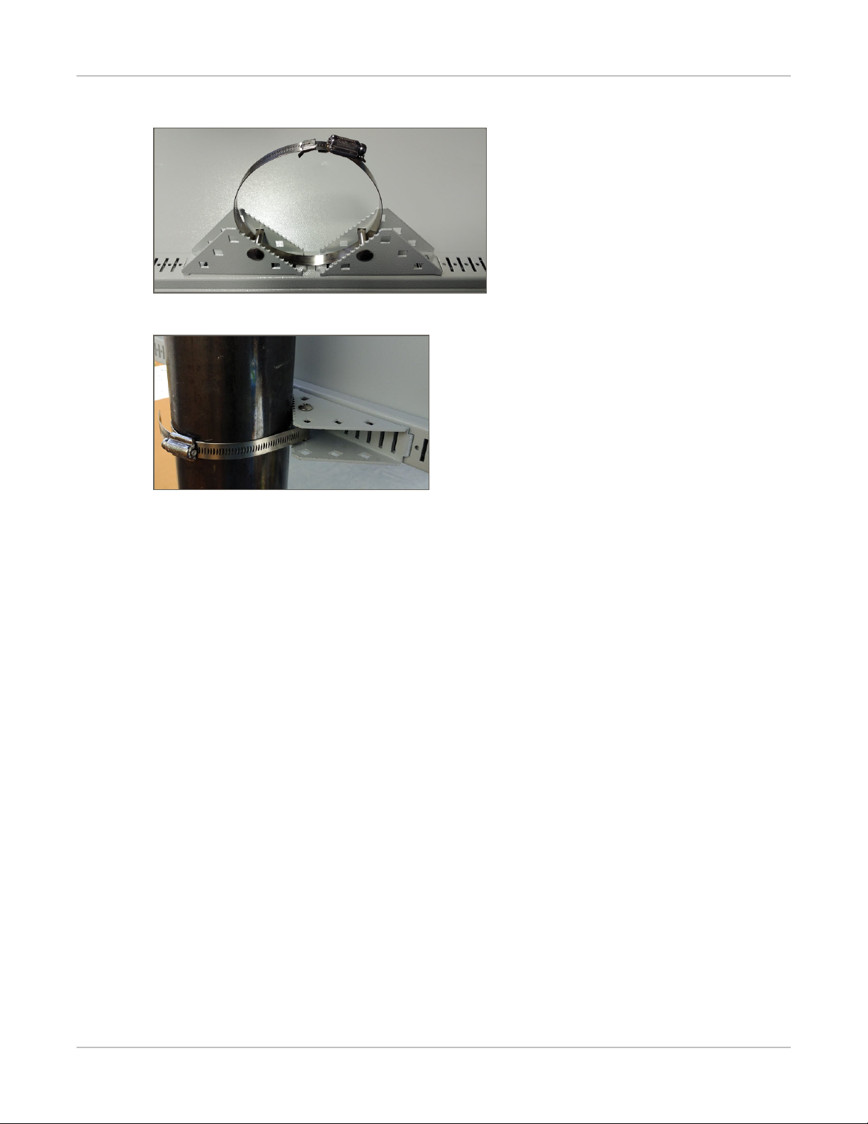
Using Pole Banding Mounting
3. Insert the stainless steel banding strap into the bracket as shown in the following image:
4. Fasten the sign to the pole and tighten the strap with a nut driver until secure.
SafePace® 500 Installation Manual p. 13

Chapter 3
POWER OPTIONS FOR YOUR SIGN
Depending on what model you have purchased, powering the sign will vary. The SafePace 500 sign is
offered in the following powering models:
»AC powered
»Solar powered (uses several rechargeable lead-acid batteries for backup)
NOTE: The warranty on the batteries is limited to 1 year — please contact Technical Support
for more details (see Contacting Technical Support on page 7).
SafePace® 500 Installation Manual p. 14

AC Power
AC Power
The SafePace 500 sign is equipped to accept 100-240 volts of AC power. For these signs (standard model),
the regulated power supply comes already pre-wired, and your sign is ready to operate once it is mounted
and wired to the incoming power supply.
WARNING: ELECTRICAL SHOCK HAZARD. To avoid serious injury or even death, all electrical wiring
should be performed by a qualified and professional electrician in accordance with local electrical
codes. Mishandling of electrical wiring may also result in damage to the unit and may void product
warranty.
WARNING: Should you need to drill holes in the sign for the AC power wiring, drill from the inside/out
as opposed to outside/in. This is to reduce the possibility of metal filings damaging the internal
components of the sign.
To wire the incoming power supply to the sign:
1. Connect the Line (BLACK) and Neutral (WHITE) wires of the incoming power supply to the marked
terminals.
2. Connect the Ground wires to the GREEN/YELLOW terminal (see Figure 5: below).
Figure 4: AC power supply terminal block Figure 5: Close-up view of AC power connectors
WARNING: It is vitally important, whenever you close the sign, that you close and lock all of the latches
properly to avoid water infiltration as this could damage the sign and void your warranty.
SafePace® 500 Installation Manual p. 15

Solar Power
Solar Power
The Solar powered model of the SafePace 500 sign includes a solar panel and mounting bracket, one or
more rechargeable lead-acid batteries, and a solar charger. The solar panel powers the sign when exposed
to sunlight while at the same time charging the batteries to provide a power backup for night-time and
cloudy day use. The solar panel is quick to install and should suffice in most installations.
Figure 6: Solar panel
Mounting the Solar Panel
You need to mount the solar panel at the highest point on the pole, optimally 10-12 feet high. Use the
supplied solar panel bracket (see Figure 7: below) and follow the instructions provided by the manufacturer
(included in the bracket’s packaging).
Figure 7: Solar panel mounting bracket
The two-part bracket allows for full adjustment in order to best position the panel towards the sun. It is
optimal to position your solar panel towards due Solar South (not magnetic South), if you are in the
northern hemisphere and towards due Solar North (not magnetic North) if you are in the southern
hemisphere.
Regardless of whether you are in the northern or southern hemisphere, Solar North/South is the position of
the sun in the sky at exactly the midpoint between sunrise and sunset.
SafePace® 500 Installation Manual p. 16

Installing the Batteries
The solar panel should be angled 15 degrees above the latitude of
the installation site. For example, if the latitude of the installation
site is 45 degrees then the solar panel should be installed at an
angle of 60 degrees, as shown.
You can easily obtain the latitude of the installation site from
mapping software or for free by doing an internet search for
"latitude your_city" where your_city is the name of the city or
region where the panel is being installed.
Installing the Batteries
SafePace 500 signs can accommodate up to six 12 volt DC lead-acid batteries. These batteries when fully
charged, can power the sign up to 2 weeks (depending on traffic volume and environmental factors).
WARNING: Proper battery care and maintenance is required. Improper care and maintenance of
batteries may void the product warranty. We strongly recommend that you do the following in order to
prevent damage to the sign and/or batteries:
• Replace the batteries every TWO years.
• Remove the batteries whenever you need to transport the sign.
• Always wire the batteries in PARALLEL as depicted in the following image.
SafePace® 500 Installation Manual p. 17

Charging the Batteries
Charging the Batteries
We strongly recommend that you charge the batteries fully before the initial use. The supplied battery
charger is equipped with a charge indicator which shows when the battery is fully charged and ready for use.
To charge the batteries:
1. Connect the charger to the battery.
2. Plug the charger into the wall.
When the charger indicates that the battery is fully charged, the battery is ready for use.
3. Unplug the charger from the wall before you disconnect the battery.
SafePace® 500 Installation Manual p. 18
Wiring the Solar Panel to the Sign
Wiring the Solar Panel to the Sign
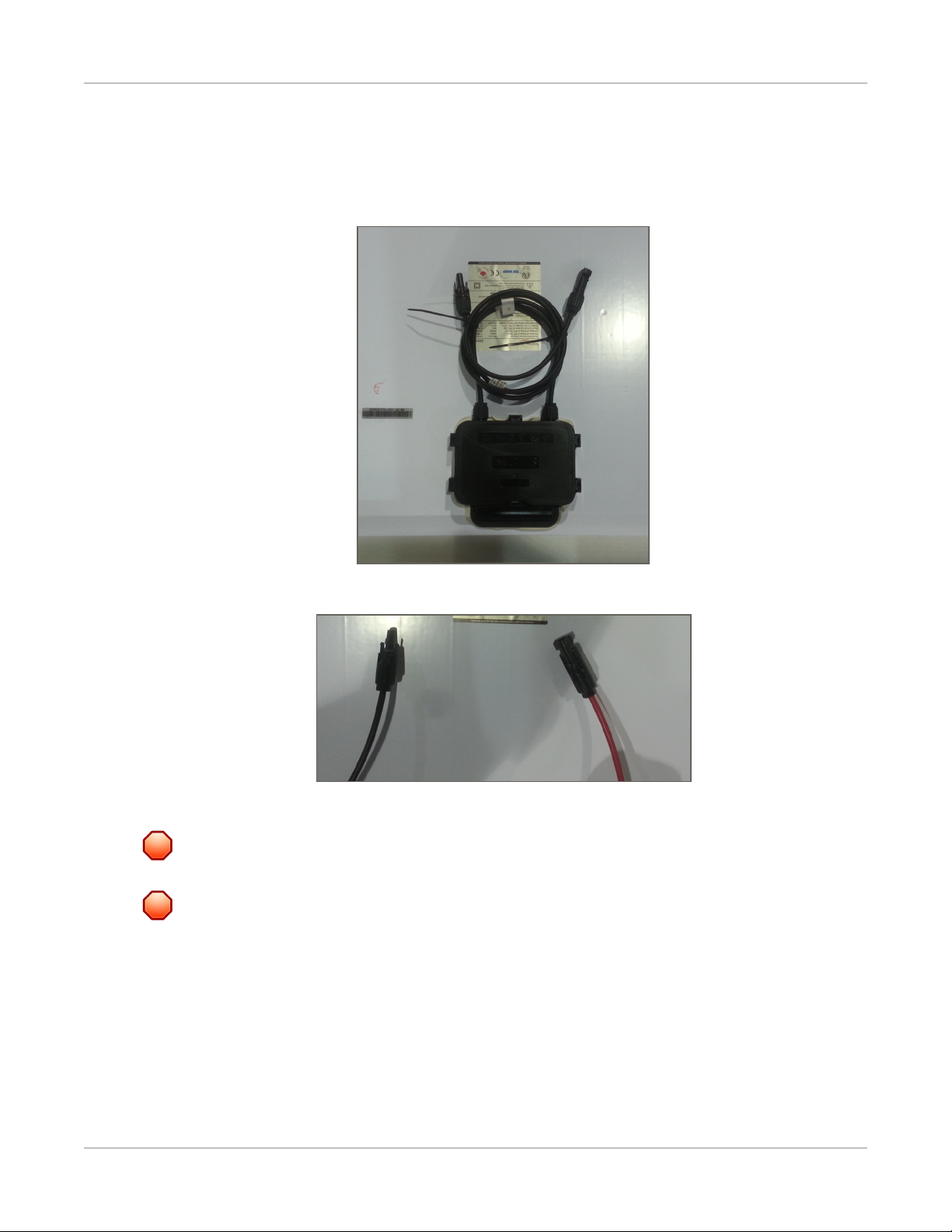
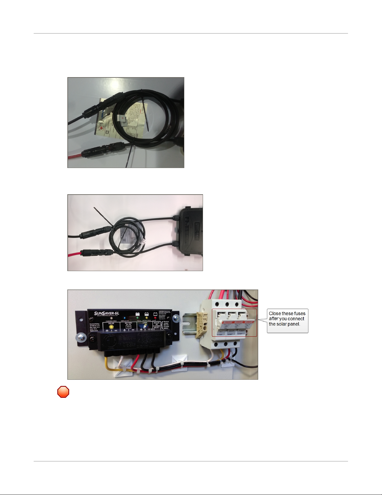
As shown in the following images, the solar panel and the sign come pre-wired with connectors that allow
for a simple installation. The red (male) and black (female) connectors from the sign need to be connected to
corresponding connectors on the solar panel.
Figure 8: Solar panel wires and connectors on the back of the solar panel
Figure 9: Wires and connectors from the sign enclosure.
WARNING: To prevent damage to the solar charger, connect the battery connectors before connecting
the Solar Panel to the sign.
WARNING: Before ever doing any maintenance on a sign, it is critical that the power is first turned off.
This will prevent accidental electrical shock that could be fatal and that could also damage electrical
components.
SafePace® 500 Installation Manual p. 19
Wiring the Solar Panel to the Sign
To wire the solar panel to the sign:
1. Insert the connectors from the sign into the corresponding connectors from the solar panel as shown
below.
2. Slide the connectors together until you hear a click and you can no longer slide them apart easily. Once
connected the cables should look like the following:
3. Open the sign then close the fuses for the solar charger, as shown in the following image.
WARNING: It is vitally important, whenever you close the sign, that you close and lock all of the latches
properly to avoid water infiltration as this could damage the sign and void your warranty.
SafePace® 500 Installation Manual p. 20
Other manuals for SafePace 500
1
Table of contents
Other Traffic Logix Industrial Electrical manuals


Popular Industrial Electrical manuals by other brands


Keysight
Keysight 849 Series Operating and service manual

Murata
Murata GRM155C71A105KE11 Series Reference sheet

Murata
Murata GRM1885C2A160JA01 Series Reference sheet

Murata
Murata GRM3195C2A222JA01 Series Reference sheet

Murata
Murata GRM1555C1E911JA01 Series Reference sheet

Murata
Murata GRT155R60J225KE01 Series Reference sheet