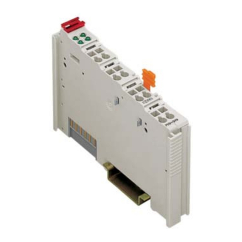
WAGO 750-337 User manual

Connection Procedure of WAGO
CANopen 750-337 Bus Coupler and
Pro-face display units supporting
CANopen master
Instruction Manual
Version 1.2(2017.09.15)

Copyright © 2008 by WAGO Kontakttechnik GmbH
All rights reserved.
WAGO Kontakttechnik GmbH
Hansastraße 27
D-32423 Minden
Phone: +49 (0) 571/8 87 – 0
Fax: +49 (0) 571/8 87 – 1 69
Web: http://www.wago.com
Every conceivable measure has been taken to ensure the correctness and completeness of this
documentation. However, as error can never be fully excluded, we would appreciate any information
or ideas at any time.
We wish to point out that the software and hardware terms as well as the trademarks of companies
used and/or mentioned in the present manual are generally trademark or patent protected.

Table of Contents
1 Devices in use............................................................................................................................................ 1
2 Installation of GP-Pro EX version 3.50..................................................................................................... 1
3 Creation of screens/programs .................................................................................................................... 1
4 Flow of CANopen setting with the software ............................................................................................. 2
4.1 Displaying the I/O Driver setting screen ............................................................................................... 2
4.2 Importing an EDS file............................................................................................................................ 2
4.3 Adding a slave ....................................................................................................................................... 4
4.4 Slave configuration................................................................................................................................ 5
4.4.1 PDO: Mapping input and output.................................................................................................... 6
4.4.2 Allocating I/O variables to the I/O tree.......................................................................................... 8
4.5 Master configuration.............................................................................................................................. 9
4.5.1 Setting a baud rate ......................................................................................................................... 9
5 Relation between objects and I/O module................................................................................................11
5.1 Catalog manager.................................................................................................................................. 12
5.1.1 Device operations ........................................................................................................................ 12
5.1.2 Catalog operations....................................................................................................................... 13
5.2 Slave configuration.............................................................................................................................. 14
5.2.1 Parameters (PDO settings)........................................................................................................... 14
5.2.2 Advanced error control................................................................................................................ 17
5.2.3 Advanced object configuration.................................................................................................... 18
5.3 Master configuration............................................................................................................................ 19
5.3.1 Network settings.......................................................................................................................... 19
5.3.2 Error control overview................................................................................................................. 20
5.3.3 Advanced object configuration.................................................................................................... 20
6 PDO protocol, SDO protocol................................................................................................................... 21
6.1 PDO (Process Data Object) protocol................................................................................................... 21
6.2 SDO (Service Data Object) protocol................................................................................................... 21
7 I/O driver instructions.............................................................................................................................. 22
7.1 SDOR, SDOW..................................................................................................................................... 22
7.2 DGMT, DGSL ..................................................................................................................................... 24
8 Transferring I/O firmware........................................................................................................................ 24
9 AGP-3****-CA1M/LT unit..................................................................................................................... 25
9.1 Offline menu........................................................................................................................................ 25
10 Installation of WAGO 750-337............................................................................................................ 27
10.1 Hardware structure........................................................................................................................... 27
10.2 Connector diagram........................................................................................................................... 28
10.3 Display elements.............................................................................................................................. 29
10.4 Hardware address (Module ID) ....................................................................................................... 29
10.5 Setting the baud rate ........................................................................................................................ 30


1
1Devices in use
This manual refers to the structure using the following devices and equipments.
- WAGO CANopen Bus Coupler 750-337 and the following I/O modules
750-337: CANopen Bus Coupler
750-430: 8-Channel Digital Input Module
750-530: 8-Channel Digital Output Module
750-600: End Module
- Pro-face AGP3400-T1-D24-CA1M
- Pro-face GP-Pro EX version 4.07.200
-
Pro-face USB transfer cable CA3-USBCB-01 (for transfer of screen data)
2Installation of GP-Pro EX version 4.07.200
1) Insert the GP-Pro EX installation DVD into the PC, and the SET UP MENU window will appear.
2) Select “GP-Pro EX”, and the Microsoft .NET Framework 2.0 set up window will appear. Follow the
Wizard to install Microsoft .NET Framework 2.0.
3)
The GP-Pro EX 4.07.200-InstallShield Wizard window will appear. Follow the direction.
-Enter the Serial Number (11 digits) on the Customer Information window.
-Enter the Key-Code.
-Follow the direction of the Wizard to install.
[Note]
When using LT3000 series, LT4000 series, SP5000 series Power Box, the [Internal I/O] screen
appears after the [Device/PLC] screen. Select the [CAN open Driver] on the pull-down menu.
3Creation of screens/programs
1) When you start up GP-Pro EX, the [Welcome to GP-Pro EX] window will appear. Select [New].
2) In the [Display Unit] setting screen, set the [Series] to GP-34**Series and the [Model] to
AGP-3400T-CA1M.
3) In the [Device/PLC] setting screen, click [New Logic] or [New Screen].
4) Create screens and/or a logic program.

2
4Flow of CANopen setting with the software
4.1 Displaying the I/O Driver setting screen
1) Select the [View] menu -> [Work Space] -> [Project Window].
2) In the [Project Window] window, click [I/O Driver] in the Peripheral Settings area, and the [I/O
Driver] screen will be shown.
[Note]
-When using LT3000 series and SP5000 series Power Box, click the [External Driver 1] tab.
-When using LT4000 series, click the [Int. Driver 2] tab.
4.2 Importing an EDS file
This section shows the procedure to import an EDS file of a WAGO 750-337 slave.
1) In the [I/O Driver] screen, click [Catalog manager].

3
2) Click [Import].
3) The [Open] dialog box will appear. Specify the 750-337.EDS file in the save-in location. Click [Open],
and the file will be registered into the [Catalog manager].

4
4) Click [Close].
4.3 Adding a slave
1) In the [I/O Driver] screen, click [Settings], and the [Network configuration] window will appear.
2) Select the item whose Key is 750-337 from the [Registered devices] list and click [Add slave], and
“WAGO 750-337” will be added in the [Assigned slaves] list.

5
4.4 Slave configuration
- Click [Slave configuration].
- The [Slave configuration] dialog box will appear.

6
4.4.1 PDO: Mapping input and output
Set PDOs (Process Data Objects), as continuous communication data.
For WAGO 750-337, the standard inputs, which are digital inputs, start from “0x6000” and the standard
outputs, which are digital outputs, from 0x6200.
1) As an example of inputs, select “Index = 0x6000.1” from the list of the [Available objects from
device profile] in the [Parameters] tab.
2) If you select “TPDO0” in the [Configured objects], the [Map] button will be enabled.
3) Click [Map], and “[0x6000.1] 1.digital input block” will be appended under “TPDO0”.
4) Set the [Data representation] in the [Setting] area to “Bit”.

7
5) As an example of outputs, select “Index = 0x6200.1” from the list of the [Available objects from
device profile” on the [Parameters] tab.
6) Select “RPDO0” in the [Configured objects] and click [Map], and “[0x6200.1] 1.digital output block”
will be appended under “RPDO0”.
7) Set the [Data representation] in the [Setting] area to “Bit” and click [OK].
Then click [OK] in the [Network configuration] window, and it will be close and the [I/O Driver]
screen will be shown.

8
4.4.2 Allocating I/O variables to the I/O tree
Allocate I/O variables after the PDO settings (mapping).
1) Click [I/O Screen] in the [I/O Driver] screen.
2) The [WAGO CANopen Buskoppler STD] tree will be shown. As an example, allocate variables to four
lower bits of 8-channel inputs.
Set the variables from “INPUT_00” to “INPUT_03” for the items from “Bit-0” to “Bit-3”, which are
under “TPDO0”. To set a variable, double click the corresponding variable field and enter the variable.
[MEMO]
* By pointing the cursor on the red marked area and dragging, you can change the column width.
3) In the same way, set the variables from “OUTPUT_00” to “OUTPUT_03” for the items from “Bit-0”
to “Bit-3”, which are under “RPDO0”.
4) Click [CANopen Driver] to return to the [I/O Driver] screen.

9
4.5 Master configuration
- In the [I/O Driver] screen, click [Settings].
4.5.1 Setting a baud rate
In the Master configuration, you can make a baud rate settings.
Baud rate settings on a slave unit can be made with the DIP switches on it.
1) In the [Network configuration] window, click [Master configuration].

10
2) In the [Master configuration] dialog box, specify the [Baud rate].
[Note]
When LT4000 series is used, the baud rate cannot be set to 500kbps and 1000kbps.

11
5Relation between objects and I/O module
The relation between objects and I/O modules is as follows. Please refer to the Modular I/O System
CANopen 750-337 Manual for the details. The values in parentheses are ones in the manufacturer area; for
example, 0x6000 and 0x2000 are the same value.
0x6000 Digital input (0x2000) 0x6200 Digital output (0x2100)
0x6401 Analog input (0x2400) 0x6411 Analog output (0x2500)
e.g.)
* Object
Data areas of objects are identified as follows.
Commutation area 0x1000 to 0x1FFFF
Manufacturer area 0x2000 to 0x5FFF
Profile area 0x6000 to 0x9FFF
* NOTE
-As for the transmission of analog input data, CAN messages can be sent even when tiny variations of
values are found. This may cause an overflow. To avoid this, the transmission of analog input data via
PDOs is deactivated by default. This communication load can be inhibited by the “inhibit time” of the
slave settings. Please refer to 5.2.1 Parameters (POD settings) for the details. For the transmission of
analog input/output data using the object 0x6401 or 0x6411, set the object 0x6423, Analog Input
Global Interrupt Enable, which is to control the transmission of analog input data using PDOs, to 1.
-For the transmission of analog input/output data using the object 0x2400 or 0x2500, the above setting is
not necessary. The objects 0x2000s to 0x5000s are in the manufacture area and they do not depend on
the above setting.
-
Index 0x6423:Analog Input Global Interrupt Enable
Sub Index0: = [ 1 ] The default value is set to “0”.
WAGO
750-337
8-CH
Digital
Input
2-CH
Analog
Input
2-CH
Analog
Output
8-CH
Digital
Output
2-CH
Analog
Input
0x6401.03
0x6200.01
0x6411.01, 0x6411.02
0x6401.01, 0x6401.02
0x6000.01, 0x6000.02

12
Details of settings with the software
5.1 Catalog manager
5.1.1 Device operations
* Import
Imports an EDS (Electronic Data Sheet) file.
The EDS file is registered in the Catalog manager of GP-Pro EX, and the contents in the EDS file is
shown in the Catalog manager.
* Delete
Deletes a designated device from the catalog in GP-Pro EX.
* Rename
Allows you to rename the key of a device registered in the catalog.
The name of the key when importing an EDS file is the EDS file name without the extension.
Up to 256 characters
* Export
Exports contents in a device registered in the catalog as an EDS file.

13
5.1.2 Catalog operations
* Export
Exports registered devices into one file (a catalog file; .cat).
By doing so, it will be easier to make the same environment in another PC.
* Import
Imports a catalog file.

14
5.2 Slave configuration
5.2.1 Parameters (PDO settings)
Up to 8 bytes (64 bits) of data can be assigned per PDO.
The transmission type can be set by each PDO.
- In the [Network configuration] window, click [Slave configuration]. In the [Slave configuration] dialog
box, select “TPDO0” in the [Configured objects] and click [Settings].
The [TPDO configuration] dialog box will appear.
* Asynchronous event
A PDO is received immediately when an event occurs regardless of the SYNC signal.
For 254, this is defined by the manufacturer.
For 255, this is defined in the device profile.
* Acyclic synchronous / Cyclic synchronous
A PDO is sent synchronizing in synchronization with the SYNC signal flowing into the network.
For the cyclic synchronous, whose SYNC cycle rate can be set from 1 to 240, when 1 is set, a PDO is
sent for every SYNC object.
When 3 is set, a PDO is sent each time that three SYNC signals flow into the network.

15
* Event timer, Inhibit time
The Event timer and the Inhibit time can be set when the transmission type is set to Asynchronous event.
The Event timer is the setting to send data consistently besides to send it when it changes.
The Inhibit time is the setting to inhibit increase of communication load by continuous data change.
* Identity settings
The master unit makes matching check between the device information (the contents of the imported
EDS file) and the actual slave unit when communication starts.
Items to be checked are follows.
Device type
Vendor ID
Product code
Revision number
[NOTE]
Check off the [Revision number] when connecting with 750-337.
When connecting with WAGO 750-337, the Device type cannot be selected.
The imported EDS file identifies if each item is enabled or disabled.

16
* Restore
Set for the master unit whether or not to restore, or write, the parameters of slave units on occasions
such as when a communication cable is disconnected and the system is recovered.
If you select “No restore”, the slave units can operate retaining the outputting signals.
Select from the following 3 for the parameter restoration.
-No restore: Parameters are not restored.
-Restore All (default): All parameters are restored.
-Man. 4: restore manufacturer defined default parameters
For WAGO 750-337, “Only Comm” and “OnlyApp” are not supported.
* NOTE
-Even if you set the object 0x6206, Error Mode Output 8-Bit, which is to retain the transmission of
output data, it is set off once when recovering from a communication error.
Table of contents
Other WAGO Industrial Electrical manuals
Popular Industrial Electrical manuals by other brands

Murata
Murata GRM0335C1E9R1BA01 Series Reference sheet

Murata
Murata GRM0335C1E2R7WA01 Series Reference sheet

Krendl
Krendl 500 owner's manual

Murata
Murata GRM0225C1E9R9CA03 Series Reference sheet

Ingersoll-Rand
Ingersoll-Rand Von Duprin 6000 Series installation instructions

Murata
Murata GQM1555C2D7R5BB01 Series Reference sheet