Trailer Vision DR-400N User manual

Instruction Manual
DR-400N
4CH DRIVING VIDEO RECORDER
* Design and Specifications are subject to change without notice.
PRINTED IN KOREAver. 1.0
Thank you for purchasing this product.
For correct usages and application,
please read this instruction manual thoroughly.

2
CONTENTS
..................................................... 3
..................................................................... 6
.............................................................................. 6
............................................................................................ 7
............................................................... 8
.............................................................. 10
.................................................................................. 10
......................................................................... 11
................................................................................ 11
.............................................................. 11
.................................................................................. 12
.............................................................. 13
.................................. 13
................................................................................................ 14
.............................................................................. 16
...................................................................................................... 18
...................................................................................... 19
........................................................................... 21
...................................... 22
SAFEGUARD INSTRUCTIONS
PRODUCT FEATURE
COMPONENTS
PARTS
INSTALL IN YOUR CAR
PRODUCT OPERATION
- Power ON/OFF
- FIRM WARE UPDATE
- Event Recording
- Abnormal Operation Check
- LED Description
PC VIEWER MANAGER
-
Installation & Execution of PC VIEWER MANAGER
- Interface
- How to play video
- Menu
- Configuration
SPECIFICATION
CHECK POINT BEFORE SERVICE REQUEST

Please read the “Safety Rules” carefully before using this product. Following the safety rules prevents users from
damages related with the misuse of the product. It is very important to follow these safety rules. We state “Caution”
and “Warning” to clarify any potential risk for a damage associated with the misuse of the product.
This information is for preventing bodily harm or even death and use should follow this safety rules.
WARNING
This information is for preventing damage or shorten the life time of the products.
CAUTION
This information is for user’s reference for better usability.
NOTICE
Please be sure to comply with below instruction if it is used the purchased storage media separately. If the
product is not used below instruction, the reorganization of HDD or recording can not work.
NOTICE
HDD/SSDs which is used for DR-400 has different specifications with each manufacturers. So, we recom-
mend to use enclosed HDD/SSD from factory for better compatibility.
- If there are some faults as use un-recommended HDD/SSDs, we do not guarantee the fault and some
repair costs will be demanded.
Please check for seamless use whether the product is working well or not at least once per month.
Please send the product to manufacturer if there is some missing list even the product is working well.
- If the disk is connected to the product, the video would be overwrite. So, image restoration may not
be possible.
The format is just for the undeclared/unselected recorded video in file list unlike normal format for PC
and the video before formatting is not visible but remain in the disk. So, the video file is represented on
the file list but, it can be showed previous videos by using playback bar located in bottom part of PC
viewer. This is not the fault but just the nature of system and it is used for restoration of the deleted file
from mistake or arbitrarily deleted video file through exporting.
The time to save the recorded video can be different from used capacity of HDD/SSD, used camera
quantity, FPS setting value and recording quality (High/Middle/Low).
It is limited to recognize the storage media directly on PC for safety.
Please equipped the HDD/SSD on the product at first use so that they can be changed to the recognized state.
SAFEGUARD INSTRUCTIONS
4
Do not place near of air bag effective range.
- It may cause malfunction of air bag or accident, injury due to hitting monitor by air bag.
Keep clean dust on power socket.
- It may cause electronic shock and fire by bad connection.
Do not put a pin or needle on the hole or crack in the body.
- In case of inserting them, stop to operate, it may cause electronic shock, fire and malfunction.
Do not use in problem condition as like smoking, smell something burn.
- It may cause fire. Stop to use and make inquiries to agency.
Should install while power off. (After install products, connect DC jack)
- It may cause to electronic shock or malfunction.
Do not operate the product while driving.
- It may cause an accident. Stop in a safe place and operate.
Do not put the product in place where sudden temperature increasing and should use on optimum
voltage, temperature and humidity. - It may cause to electronic shock or malfunction.
Do not pull cord with a jerk, should catch a plug and pull. Do not use damaged cord.
- It may cause cord malfunction, electronic shock and fire.
Do not clean exterior with alcohol, volatility or oily solvent. Neither keep touching rubber and plastic
for long time.
- It may cause change of surface, fall of paint, malfunction and fire.
Please use the USB cable at 2 USB ports together when checking the data.
- If only one USB port is used, the power may not be supplied well and the hard disk could not be read.
Please do not install the product where has lots of vibration or not fixed securely. - It may cause traffic
accident and injury due to an interruption from detaching the product by vibration during driving.
Please avoid wiring of connected codes from high fever.
- It may cause electric shock and fire from melting of covering for codes.
WARNING
Please confirm the caution according to a kind of vehicle if the vehicle has an air bag.
- It may cause malfunction of air bag if it installed and wired at the wrong place.
Please prevent the loss of power during update.
If the power is lost during update, the product may not be working.

5
When install ordinary power cable, should contact to a specialty store. (The place of fuse box is varying
depending on each car manufacturer. Please check the car manual before installation)
To safe usage on battery, please disassemble ordinary power cable when you do not drive for a long
time (over 3 days). We recommend disassemble to safe driving even though this cable contains a func-
tion for preventing battery dead.
Do not disassemble, repair and remodeling.
- It may cause malfunction and injury, can not get warranty. Make inquiries to agent for repair and
checkup.
CAUTION
Do not place near magnet.
- It may cause malfunction and trouble.
Keep the internal GPS without any obstacle near of it like high pass, navigation.
- It may cause problem on GPS signal receipt rate.
GPS function needs loading time when it power on.
- It needs from few seconds to minutes depending on signal receipt environment.
The vehicle which has metallic tinting on front window could be caused poor
GPS reception.
In case of suddenly changing of brightness such as tunnel enter/exit or extremely dark place, the re-
cording quality may be low.
When you drive dark place, recommend you to turn on the headlight (fog light) to record with high
quality.
Do not shock to the product.
- It may cause damage or malfunction for product.
Please use only the specified components.
- If it is used with non-specified components, it’ll be caused an accident or breakdown of the product
because it damaged the components inside of product or is not fixed properly.
After wiring for the codes, please move it to the location where is not interrupted of driving and coil the
codes with friction tape and fix it by clamp.
- It may cause electric shock or fire as the codes are contacted with the part of car frame.
- It may cause traffic accident if the steering or selector or brake pedal is twined.
Please wire the codes without the contact with moving parts such as seat rail, screw parts and car frame.
- It may cause electric shock and fire by disconnection of short circuit.
After installation and wiring, please make sure that Brake, Light, Horn, Etc. are operated properly.
- It may cause electric shock and fire, if the product used as above functions are not operated properly.
Please careful do not interfere with electric wiring when product is installed in the upper part of dash-
board.
- It may cause ignition from a bundle of electric wiring and it makes product damaged.
Please install the product at a level with HDD.
- If the product installed as standing, HDD cannot be read and be recorded.
The viewer does not run properly when the sound driver is not installed on user’s PC or forced to off the
sound device. (Sound GUI disabled state). - Please re-run the viewer after confirming that the sound
device is working properly when there is the message“Sound device open error” twice.
When the HDD is used for product, please install the product horizontally. It could not be recorded the
video if the product is installed to upright or tiled considering of the nature of Hard disk.
Please use Hard disk for only DVR recording. - If the HDD/SSD is used as normal exterior hard disk to
state of NTFS or FAT32 format, there can be serious problem on hard disk or recorded video is broken

6
PRODUCT FEATURE
1
COMPONENTS
2
DVR body
(including the Key)
Remote controller
(optional)
Remote Controller
Receiver
GPS antenna
(optional)
Video output cable
(optional)
Ordinary power cable
(optional)
USB
download cable
MIC. (optional)
Ext. sensor cable
(optional)
PC VIEWER
install CD
Instruction
Manual
Bracket set
Cable
(Water proof type)
MEMORY
case
1
E2
3
4
DVR
* If the body and parts mentioned below are not included when you purchase this prod-
uct, contact the shop where you purchased the product.
*The shape of each component may be changed without notice for the better quality.
- AUTO RECORDING (DIRIVING, ACCIDENT, ETC..)
- H.264
- PC VIEWER MANAGER
- 4 TRIGGERS
- UP TO 1TB HDD OR SSD SUPPORT
- LOCK SYSTEM FOR HDD OR SSD (2.5” HDD OR SSD)
- EXTERNAL MIC.
- BEEP SOUND (EVENT RECORDING, FIRM WARE UPDATE & ETC.)
- Integrated 3G-Sensor
- Trace of trajectory interlocked with map
- Emergency battery equipped (with Super capacitor)
- FREE VOLTAGE (DC 12 ~ 24V, Max 32V)

7
PARTS
3
DR-400N
REMOTE CONTROLLER
1
1
E2
2
3
3
4
4
Front of DVR body
Back of DVR body
1. Camera Operation LED
2. Recording LED
3. Remote Controller Sensor
4. Hard Case
5. CASE LOCK
6. MEMORY LOCK
7. TRIGGER
8. MIC / GPS / REMOTE CONTROLLER
9. POWER CABLE
1. EMERGENCY RECORDING
- About 30seconds Recording
2. Video Switch of Cam 1, 2, 3, 4 (Single Screen)
3. Split Screen Mode
“Event recording file saves in MANUAL
Folder from recording of remote controller.”

8
1
34
2
Insert and installation of memory to the
MEMORY case
MEMORY
(128GB SSD Included)
Please check the following points prior to installation:
- Turn off the product before installation, and install the product with the ignition key removed.
- Do not use any other cables; only use the supplied cables.
- If the vehicle has a tinted or heated screen the GPS receiver rate may be 'poor' & an external GPS
antenna may be required (initially try mounting the antenna near a side window etc)
- Please install the product horizontally if utilised with HDD Memory.
4 INSTALL IN YOUR VEHICLE
9
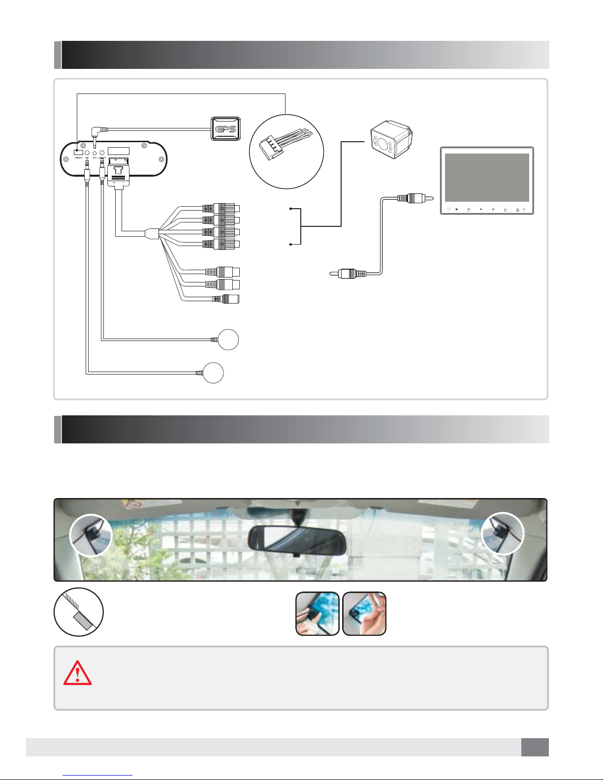
Yellow (Video)
White (Audio)
Back of DVR body
GPS antenna
(Included)
Camera (optional)
Monitor (optional)
Video out cable
(optional)
Remote controller receiver
MIC (optional)
TRIGGER Cable
CAMERA 1
CAMERA 2
CAMERA 3
CAMERA 4
CABLE CONNECTION
Connection with GPS antenna (optional)
When connected to the GPS antenna driving route, speed, time, direction and location information is also
recorded.
* Recommended position of Installation
Install with the “GPS” logo
facing upwards.
Tinting section
GPS antenna
Position GPS antenna does not
overlap the tinting section.
The GPS signal receipt could be reduced by tinting or windscreen coating material or
heating elements. It is not a product fault and is caused by the metal components. In
this case the antenna should be installed outside or on a side window etc.
(Optional)
10
PRODUCT OPERATION
Power On/Off & Recording Status
5
Please note:
- Please do not operate/change settings during driving.
- Please connect GPS, VIDEO OUT, MIC before turning the ignition on.
- After unit power on, it may reboot. This is not a device fault.
- Recording is only possible when the MEMORY tray is inserted & locked.
- If the MEMORY is removed while in operation, some or all of the data may be
lost.
*If the memory is full, the oldest data is deleted sequentially and overwriten by new data.
There are 3 folders of Data: 'Normal', 'Event' and 'Manual' saved in the MEMORY (SSD) and the
recording ratio is about 3:1 of the capacity (i.e. 3 parts 'Normal' to 1 part 'Event/'Manual'.
1. This product has no separate power button (the unit is powered via ignition, a timer for 'igntion off'
recording is also available).
2. When the vehicle’s ignition is turned off the system will be shut down after saving
files securely.
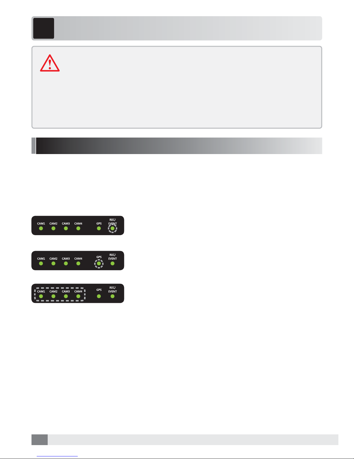
4. The GPS LED flashes when GPS is connected and receiving GPS
signal, the LED then stays on. (If the GPS antenna is not
connected, the LED does not illuminate.)
5. If the Emergency button on remote controller is pressed,
event recording will start & continue for 30seconds. (REC/
EVENT LED is flashing 3 times at 1 second.)
3. The EREC / EVENT LED flashes at intervals of 1 second when
recording.
*Normal recording creates a file at intervals of 5 minutes.

11
Abnormal Operation Check
Event Recording
FIRMWARE UPDATE
1. If a camera is not recording, the LED for that camera will be off.
In this case, the camera which has a fault won’t be recorded.
2. If the Memory tray is removed or fails, all CAM (1-4) LEDs
flash at an interval of 1 second and the unit 'beeps' until power
is turned off.
1. CAM1/CAM2/CAM3/CAM4 LED flash at an interval of 1 sec
during firmware update and a beep will be sound once the
firmware update has completed.
*Power should not be turned off during update.
3. If there are no inputs at the all channels or all the
cameras are turned off, all LEDs will be off.
1. Event Recording : the unit records for 10 seconds before
and 20 seconds after an event (accident) occurs (30 seconds in
total).
5 min.
4 min. 30 sec.
For example, if an event happens 9 minutesand 40 seconds after starting recording:
10 sec. 20 sec.5 min. 5 min. 5 min.
Event
Save as a Ordinary
recording file
(5min.) The portion other than images before 10 seconds from 9 minute and 40 seconds
after an event happens will be saved as a file of normal recording (4 minute and 30 seconds).
Event recording Ordinary recording
9min. and 40 sec.
Recording mode & time
Continued...
* Odinary Recording : Independent of events, the unit continues recording at intervals of 5 min.
* Event/Motion Recording : The unit recordsfor 10 seconds before and 20 seconds after
an event (accident) happens. (30 seconds in total)
5 min.5 min. 5 min. 5 min. 5 min. 5 min.
Normal recording section
Event recording section
Event
10 sec. before
an event
20 sec. afer
an event
Event recording starts with beep sound.
12
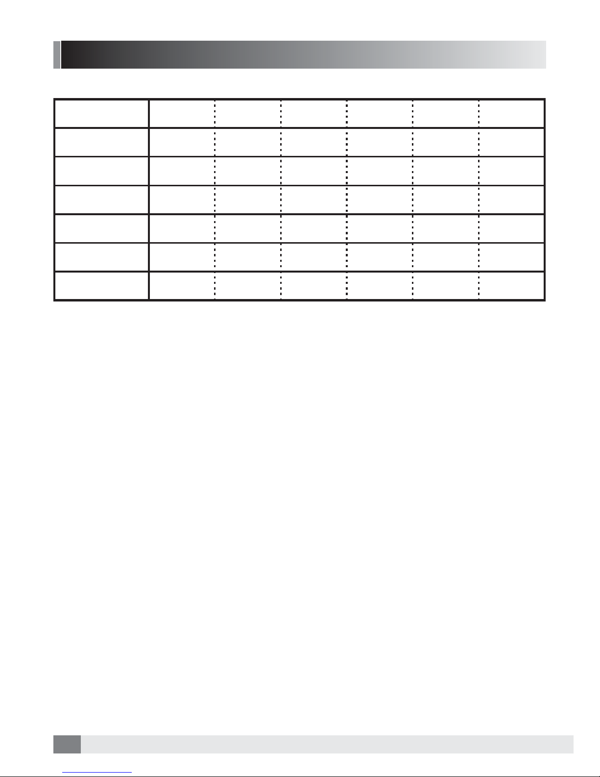
LED Description
*Condition: 4 camera connection
ON(Stand-by)
ON(Recording)
-
-
-
-
Flashing Flashing Flashing Flashing
-
-
-
-
-
-
-
-
-
-
-
-
LIGHT ON
LIGHT ON
LIGHT ON
LIGHT ON
LIGHT ON
LIGHT ON LIGHT ON LIGHT ON LIGHT ON -
LIGHT ON AFTER
15SECONDS
Flashing
(1 second interval)
Flashing
(1 second interval)
Flashing
(Quickly)
Flashing
(Quickly)
Light on and out
GPS
EVENT RECORDING
EMERGENCY
RECORDING
MEMORY ERROR
STATUS CAM1 CAM2 CAM3 CAM4
GPS REC/EVENT
13
PC VIEWER MANAGER
6
Installation & Execution of PC VIEWER MANAGER
Specifications of PC VIEWER MANAGER
CPU : Pentium 4 3.0GHz at least
OS : WINDOWS XP/ VISTA/ 7/ 8 / 10
Memory : 2GB RAM at least
HDD : Supported within 1TB
User Authority : Administrator
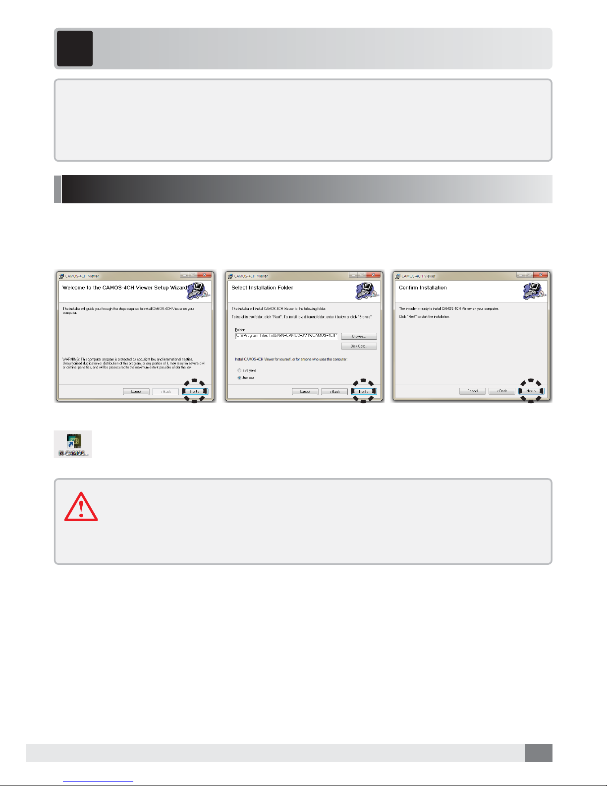
PC VIEWER MANAGER needs to be installed. Put the enclosed CD in your PC, double-click the
setup.exe file, and complete the following installation:
When the PC viewer installation is completed, an icon will be created on PC screen.
Please double-click the icon to execute.
-There will be a message about the requirement to format the memory when the
recording data is over 1 week old
-Please regularly format the memory
-Please check/format the memory if recording data is not displayed in the viewer’s
file list.

14
Display quad recorded video
Display 3G sensor information.
Adjusts sound. (mute/volume +,-).
Previous File/Backward/Play(Pause)/Forward/Next File.
Adjusts play speed (x1/4 ~ x4).
Minimizes the program (with the Taskbar).
Displays the recording video suitably to 1:1 size.
Displays just the recording video in form of a full wscreen.
(To return push the ESC key.)
Maximizes the program. (Maximizes the program relative to the monitor screen size.)
Ends the program.
Open recorded data / memory tray.
Searches the file list by date and time.
Map information Display driving route on the map.
Displays GPS information at the driving time.
Outputs the displayed data as a'screen shot'.
Save the data as .bmp or .avi files.
Change settings (time, resolution etc).
Interface
1. Play screen
2. 3G sensor
3. Volume control
4. Movie control
5. Play speed control
6. Minimize
7. 1:1 screen
8. Full screen
9. Maximization
10. Exit
11. Open file
12. File search
13. Map
14. GPS info.
15.
Output of Event Report
16. Save file
17. Configuration
15
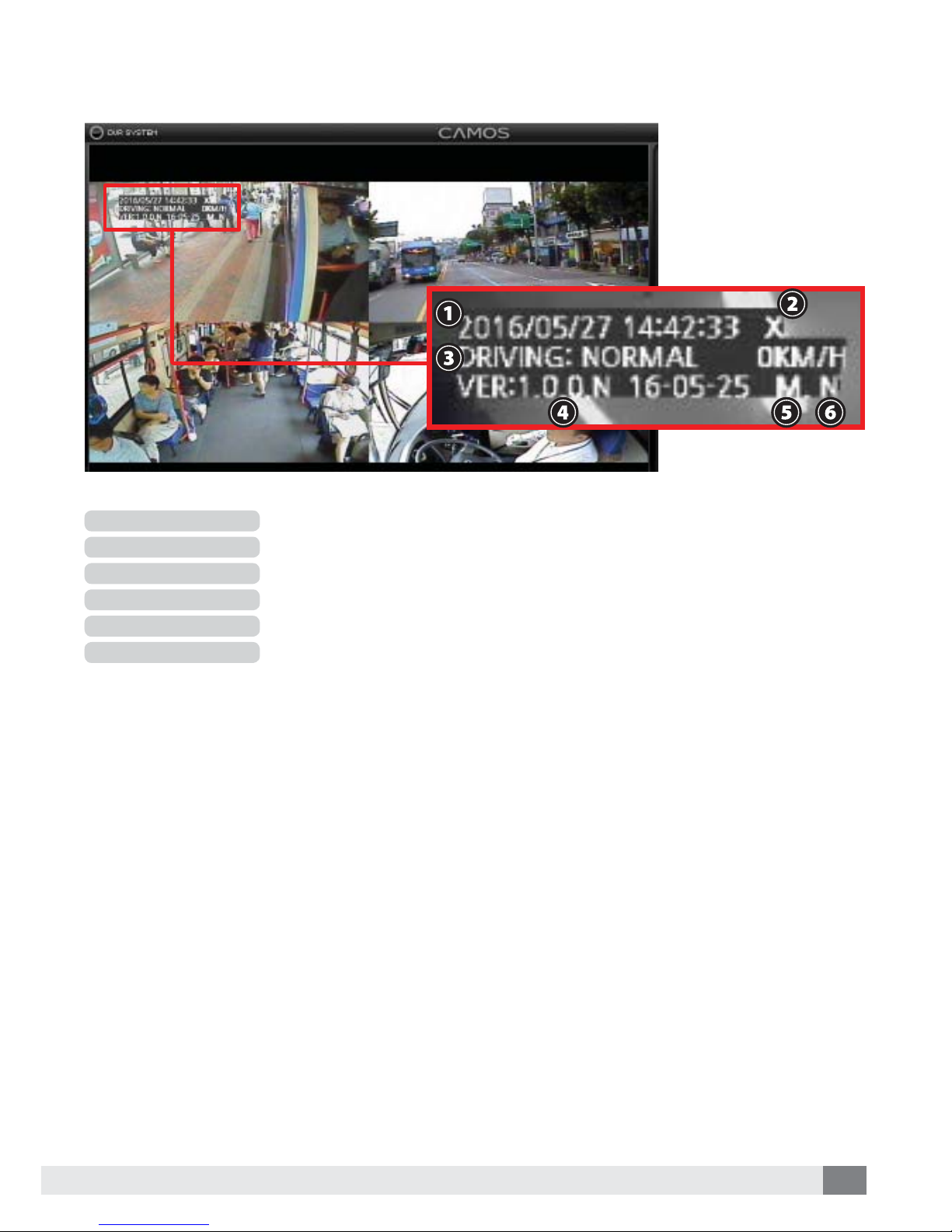
Displays the present time and date.
Displays the status of the GPS connection. (Connection : O, Disconnection : X).
Displays the recording status (NORMAL / EVENT).
Displays the Firmware version.
Connection of Mic. : M / No connection of Mic. : X).
Recording with Standard quality : N / Recording with High-Definition quality : H).
1. Time & Date
2. GPS
3. Recording
4. Version
5. Mic. Connection
6. Video Quality

16
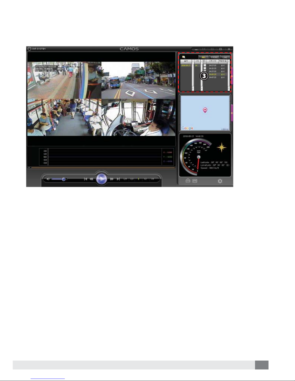
How to play video
2. ①”Please click “file reading”
② Please select memory and click confirm.
1. Please open the software on the PC.
17
3. ③ Please double click the file for playing video.

18
Menu
1. Click the right button of mouse at screen, following menu will be shown.
Changing the playback screen : Playback screen changes as left and right.
Screen ratio : Control recording data screen’s ratio.
Video : It turns around upside and downside
/ I turns around left and right
1CH video : Video is displayed as full size.
19
Configuration
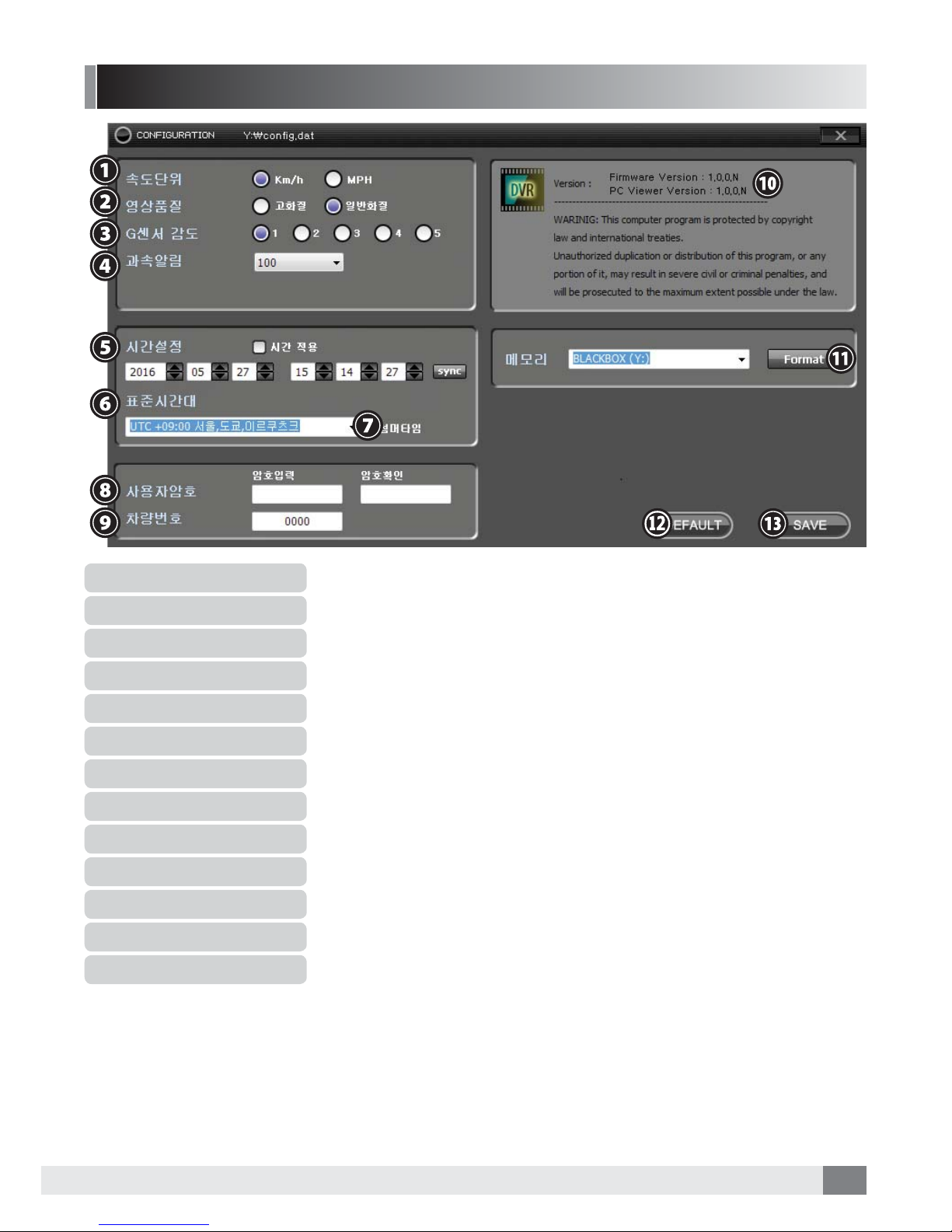
1. Speed Indicator Unit
2. Recording Quality
3. G-sensor Sensitivity
4. Overspeed
5. Time setting
6. Time zone
7. Summer Time Apply
8. User’s password setting
9.
User Car Number Setting
10. Version
11. Memory format
12. Initialize
13. Setting Saving
Selects the speed indicator unit of GPS information (km/h, MPH).
Sets the recording quality (High-Definition / Standard).
Set G-sensor Sensitivity (5steps : 1 (Low) - 5 (High).
If speed goes beyond the setting speed, the file saves as event file.
Sets the time (press sync button, to set the present time from the PC).
Select time zone of the country of operation.
Applies summer time.
Input User’s password (if required).
Set the car/vehicle fleet number/registration.
Show viewer and firmware version.
Format all recording list in memory.
Initializes the whole setting (factory defaults).
Saves the changes. (Without connection of memory, save as user’s setting at PC).

20
“Timeset.cfg” file will be created after checking
time setting and saving the value. This means time
setting is correctly set. Please check this status be-
fore device operation.
Table of contents
Other Trailer Vision DVR manuals


