TRAILPARTS Credo User manual
1300 538 598
www.trailparts.com.au
[email protected]om.au
TRAILPARTS PRODUCT
HOW-TO GUIDE
4500KG
GVM
WIRING INSTRUCTIONS FOR
Trailparts Credo Brake Control
to suit electric drum brakes
TM TM

CREDO CAB CONTROLS
The Trailparts™ Credo™ Braking system meets Australian Design Rules 38
2
1300 538 598
www.trailparts.com.au
[email protected]om.au
TO OPERATE:
>
>
>
>
>
>
charge.

-
0
EMERGENCY
STOP
LESS MORE ADJ.
+
GAIN SENS.
ZzP
Screen sleep
Gain control
Braking level
Emergency brake
Tail-light indicator
1
2
3
4
5
6
7
CREDO CAB CONTROLS
1
Screen Sleep Button
2
Gain Control - Adjusting Gain Control:
3Braking Level
4
Emergency Brake
5Tail-light Indicator
6Hand-piece Battery
7
Sensitivity Control
Credo Cab Controls
3
1300 538 598
www.trailparts.com.au
[email protected]om.au

CREDO SCREEN CONTROLS AND WARNINGS
Headlights Warning
Low Trailer Battery Warning
Sleep Menu
cancel to return to the home screen.
to be plugged into power again to wake up.
4
1300 538 598
www.trailparts.com.au
[email protected]om.au

CREDO INSTALLATION INSTRUCTIONS
5
1300 538 598
www.trailparts.com.au
[email protected]om.au
>
on page 7.
>
>
>
electric drum brakes.
>
the brake controller output earths as shown in the diagram. They cannot be
connected to a common chassis earth.
>
>
controller and cannot bypass this directly to the trailer plug.
>There is a spare orange wire and pink wire that are not used when installing on
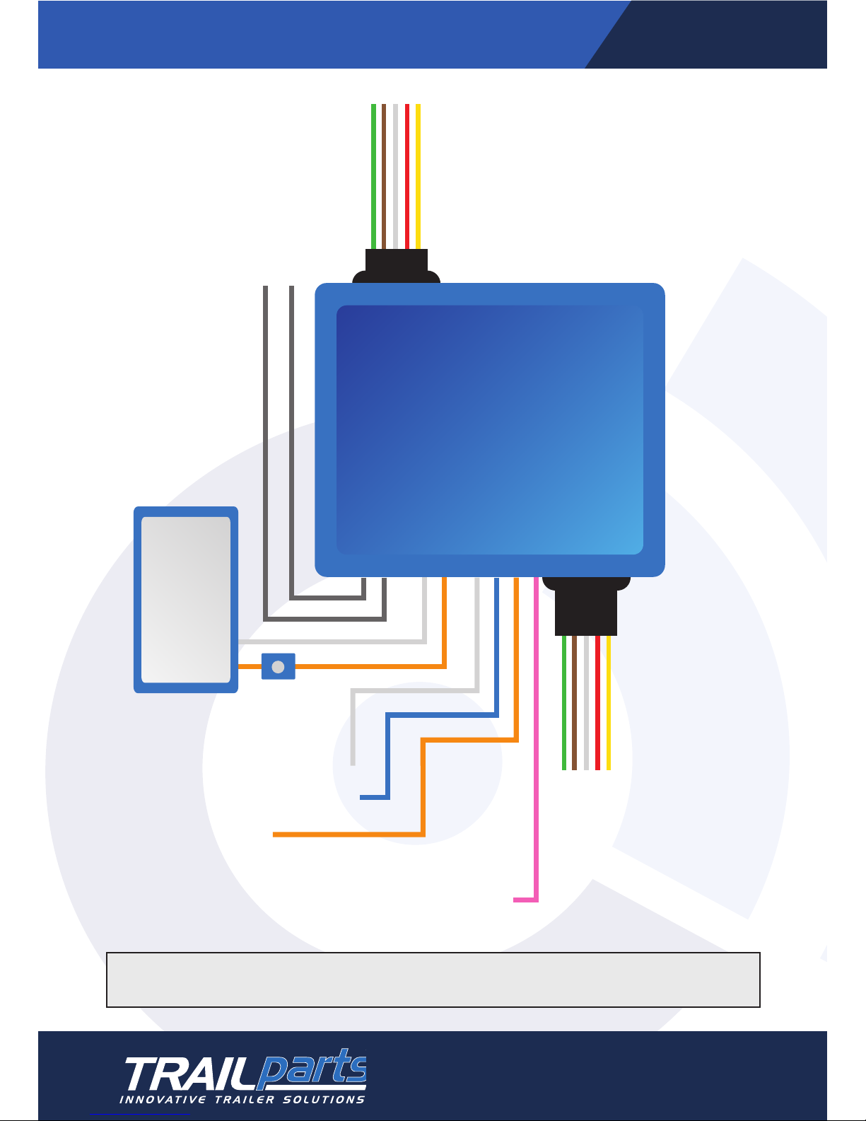
ELECTRIC DRUM WIRING DIAGRAM
6
1300 538 598
www.trailparts.com.au
[email protected]om.au
Connect one grey to each side
of the breakaway switch
White to Electric Drum Earth
Blue to Electric Drum Positve
Orange is not used
Green - Right Indicator
Brown - Tail light
White - Earth
Red - Stop light
Yellow - Left Indicator
Connect trailer lights to
5 core output
Battery Connections
White Negative
Orange Positive
One 5 Amp/hr
battery
Must be fitted
with battery
supplied.
Do not use
brake system
battery to
power any
other systems
There should be no more
than 2.5 metres of cable
between the controller and
the trailer plug to avoid
voltage drop.
30amp Fuse
Pink not used

TOP
TOP
Direction of Travel
Must be mounted straight longitudinally, i.e. parallel to direction of travel
INCORRECT
CORRECT
90
o
FRONT
FRONT
Unit Must Be Level
Laterally
INCORRECT
CORRECT
90
o
SIDE
Direction of Travel
SIDE
Back can be up to
70 Degrees Up
Back can be up to
20 Degrees Down
20
o
70
o
OR
DIRECTION OF TRAVEL
FRONT
FRONT
Unit Must Be Level
Laterally
INCORRECT
CORRECT
90
o
Unit must be level laterally
Direction of travel
Back can be up to 70 degrees up Back can be up to 20 degrees down
OR
7
1300 538 598
www.trailparts.com.au
[email protected]om.au
ON-TRAILER MODULE MOUNTING ORIENTATION

MAINTENANCE AND CHECKS
>
>
>
>
OTHER INFORMATION
numbers.
www.trailparts.com.au
1300 538 598
1300 538 598
www.trailparts.com.au
[email protected]om.au
FOR MORE INFORMATION
Other manuals for Credo
1
Table of contents


