LI-COR 7200-101 User manual

7200-101
Flow Module
Instruction Manual


7200-101 Flow Module
Instruction Manual
LI-COR Biosciences
4647 Superior Street
Lincoln, Nebraska 68504
Phone: +1-402-467-3576
Toll free: 800-447-3576 (U.S. and Canada)
envsales@licor.com
Regional Offices
LI-COR Biosciences GmbH
Siemensstraße 25A
61352 Bad Homburg
Germany
Phone: +49 (0) 6172 17 17 771
envsales-gmbh@licor.com
LI-COR Biosciences UK Ltd.
St. John’s Innovation Centre
Cowley Road
Cambridge
CB4 0WS
United Kingdom
Phone: +44 (0) 1223 422102
envsales[email protected]om
LI-COR Distributor Network:
www.licor.com/env/distributors

NOTICE
The information contained in this document is subject to change without notice.
LI-COR MAKES NO WARRANTY OF ANY KIND WITH REGARD TO THIS MATERIAL, INCLUDING, BUT NOT
LIMITED TO THE IMPLIED WARRANTIES OF MERCHANTABILITY AND FITNESS FOR A PARTICULAR PURPOSE.
LI-COR shall not be liable for errors contained herein or for incidental or consequential damages in connection with the
furnishing, performance, or use of this material.
This document contains proprietary information, which is protected by copyright. All rights are reserved. No part of this
document may be photocopied, reproduced, or translated to another language without prior written consent of LI-COR,
Inc.
© Copyright 2010, LI-COR, Inc.
Publication No. 984-11013
Printing History
New editions of this manual will incorporate all material since the previous editions. Update packages may be used
between editions which contain replacement and additional pages to be merged into the manual by the user.
The manual printing date indicates its current edition. The printing date changes when a new edition is printed. (Minor
corrections and updates which are incorporated at reprint do not cause the date to change).
Microsoft® and Windows® are registered trademarks of Microsoft Corporation. Eurofast® is a registered trademark of
Turck Inc.
LI-COR, Inc. l4647 Superior Street lLincoln, Nebraska 68504
Phone: 402-467-3576 lFAX: 402-467-2819
Toll-free: 1-800-447-3576 (U.S. & Canada)
envsales@licor.comlwww.licor.com
1st Printing - March, 2010
2nd Printing – October, 2013
ii

iii
Contents
Section 1. Overview of the 7200-101 Flow Module
What’s What 1-1
Initial Setup 1-2
Powering the 7200-101 1-2
Cabling 1-2
Attaching the Tubing and Air Filter 1-3
Mounting the 7200-101 Flow Module 1-5
Using the 7200-101 1-7
Controlling Flow with Manual Controls 1-7
Controlling Flow with the Windows® Software 1-10
Monitoring Flow Rate 1-11
Flow Rate Data Output 1-12
Section 2. Maintenance
Changing the Fuse 2-1
Cleaning the Air Filter Screen 2-2
Appendix A. Specifications
Appendix B. Warranty

iv

Section 1.
Overview of the 7200-101 Flow Module
The 7200-101 is a high performance flow module designed for use with the LI-
7200/RS enclosed CO2/H2O Analyzer, or other closed path analyzers. The 7200-101
attaches to the LI-7550 Analyzer Interface Unit of the LI-7200/RS to provide an
integrated flow solution; flow can be controlled through software, or manually via
the 7200-101 control panel. The 7200-101 provides a constant flow of 10-18 SLPM,
in increments of 0.1 SLPM, and requires only about 13W power during normal
operation.
What’s What
If you have just taken delivery of your 7200-101, check the packing list to verify
that you have received everything that was ordered and that you have also received
the following items:
lMounting Kit – (part number 9979-022). This kit contains all of the hardware
needed to mount the 7200-101 Flow Module to a tripod or other mounting
post.
lSpare Parts Kit - (part number 9972-049). This kit contains replacement parts
for your 7200-101. Among other items, the spares kit contains tubing and the
power and accessory cables. As you become familiar with the Flow Module you
will learn which items to keep close at hand and which items can be stored
away. The spares kit includes these commonly used items:
Description Quantity Part Number
Tygon Tubing, ¾” O.D.; 16.4' (5 meters) length 1 222-10384
Hose Barb, 3/8” NPT 1 300-11179
Hose Barb, 1/4” NPT 1 300-11180
1-17200-101 Flow Module

Section 1. Overview of the 7200-101 Flow Module
Description Quantity Part Number
Hose Clamp, ½” O.D. 4 300-10788
Air Filter 1 301-10381
Air Filter Replacement Screen 2 301-10382
Accessory Cable, 5 meter, 5PF-5PM 1 392-10092
Exhaust Fitting 1 6572-047
Power Cable, 5 meter 1 9975-030
Initial Setup
This section describes basic operation of the flow module.
Powering the 7200-101
The 5-meter power supply cable included (part number 9975-030) has a circular
connector that attaches to the 7200-101 Flow Module front panel at the location
marked POWER. The other end has bare wire leads for connection to a 10.5-30
VDC supply (50 W or more capability, 2 A or greater). Connect the red lead to the
positive terminal of the power supply, and the black wire to the negative terminal.
Cabling
The 5-meter Accessory cable included (part number 392-10092) has male and
female circular connectors that attach to the 7200-101 and LI-7550 front panels,
respectively, at the connectors marked ACCESSORY.
Figure 1-1. Attach the Accessory Cable to the Accessory connectors on the LI-7550 and
7200-101 front panels.
1-2 7200-101 Flow Module

Attaching the Tubing and Air Filter
IMPORTANT: Clamping the tubing to the hose barbs and air filter as described
below is very important. The tubing will initially seal without hose clamps, but
in our experience, leaks will develop slowly over time. Note, too, that the Tygon
tubing should not be draped over support stands or other equipment, as it can
soften in sunlight and warm weather, causing it to kink, resulting in flow restric-
tion.
There is a 16’ length of ½” I.D. Tygon tubing in the spares kit that is used for air
flow between the LI-7200/RS sensor head and the 7200-101 Flow Module. We
recommend that you always attach the air filter in-line between the LI-7200/RS
sensor head and the 7200-101 AIR IN port. Follow these steps to attach the Tygon
tubing and air filter:
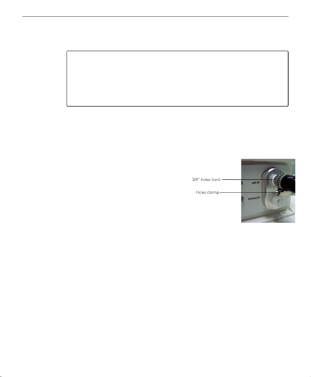
Figure 1-2. Thread the exhaust fitting
into the EXHAUST port and hand
tighten. Thread the 3/8” hose barb into
the AIR IN port.
1Remove the red shipping plugs from the
EXHAUST and AIR IN ports.
Screw the white exhaust fitting into the
EXHAUST port on the 7200-101 front
panel. Tighten with an open end wrench;
this fitting serves to hold a small filter
screen in place inside the port.
2Locate the 3/8” nickel plated hose barb in the
spares kit (part number 300-11179).
Thread the hose barb into the AIR IN port.
Tighten with an open end wrench.
3Cut a 4” section from the length of Tygon tubing.
Place a hose clamp over this section of
tubing, and push onto the hose barb. Tighten the hose clamp. TIP: Use a pair of pli-
ers to tighten the hose clamp initially; after you have tightened the clamp once,
you’ll be able to tighten the thumb screw by hand.
4Place another hose clamp over the short section of tubing, and push the tubing onto the air filter.
Note the orientation of the filter; the arrow on the body of the filter must face toward
the instrument.
Section 1. Overview of the 7200-101 Flow Module
1-3Attaching the Tubing and Air Filter

Section 1. Overview of the 7200-101 Flow Module
Figure 1-3. Note the orientation of the
arrow on the body of the air filter, and
clamp onto the short length of tubing.
You can now clamp the long length
(however long you determine is needed
to run to the LI-7200/RS sensor head) of
tubing onto the other end of the air filter,
and run the tubing to the AIR OUT port
on the LI-7200/RS sensor head (the
7200-101 draws air through the sensor
head).
Note that the LI-7200/RS sensor head
ships with two Swagelok fittings installed
in the air inlet and outlet ports. You will
need to remove the Swagelok fitting on
the AIR OUT port and install the ¼” hose
barb (part number 300-11180, in the
spares kit) to attach the Tygon tubing. Clamp the tubing at the hose barb on the
LI-7200/RS sensor head with a hose clamp from the spares kit. The finished cabling
configuration (including optional 7550-101 Auxiliary Sensor Interface and sonic
anemometer) might appear something like that shown in the illustration below.
1-4 7200-101 Flow Module

LI-7550 Analyzer Control Unit
LI-7200
7200-101 Flow Module Power Supply
Anemometer
Data
Cable
Air IN
Filter
1/2” ID Tygon Tubing
ACCESSORY
Power Cable
Air OUT
VOLTAGE
CURRENT
VIN+
VIN-
Mounting the 7200-101 Flow Module
Two mounting plates (part number 9879-045) are included that can be used to
mount the 7200-101 using hose clamps to secure the box to a tripod or other post.
There are holes in the four corners of the box, as well, that can be used to attach
the box directly to a flat surface, if desired.
The mounting plates and hose clamps are designed to accommodate a square or cir-
cular mounting post of up to 2.75" in width (diameter). Hardware is included to
attach the mounting plates to the 7200-101 using 4 hex head bolts (part number
150-12943). The hose clamp mounting brackets are attached to the mounting
plates, and then the hose clamps can be inserted through the holes in the hose
clamp mounting brackets, and tightened around the post, as shown in Figure 1-4 on
the next page. The hose clamp mounting brackets can be inserted through any of
the holes in the mounting plates to accommodate a variety of mounting options, as
shown in Figure 1-4 on the next page.
Section 1. Overview of the 7200-101 Flow Module
1-5Mounting the 7200-101 Flow Module

Section 1. Overview of the 7200-101 Flow Module
7200-101
1
1
2
3
7
8
4
5
6
7200-101
Flow Module
7200-101
Flow Module
7200-101
Flow Module
2
Figure 1-4. Attach mounting plates to the 7200-101, attach hose clamp mounting brackets
to mounting plates, and secure to mounting post using hose clamps.
Item Qty. Part Number Description
1 4 150-12943 M6x1 × 16 MM Hex Head Bolt
2 4 167-02054 Flat Washer 1/4 x 5/8”
3 2 167-05635 Split Washer 5/16”
4 2 235-13234 Single Bolt Flared Leg Mounting Bracket
5 2 300-13293 Hose Clamp, 9/16”
6 2 9879-045 Mounting Plate
7 2 included w/ item #4 5/16-24 × 1/2” Hex Head Bolt
8 2 included w/ item #4 5/16” Flat Washer
Table 1-1. Mounting kit parts.
There are some additional considerations that should be taken into account when
locating the Flow Module, including:
lThe Accessory cable that connects to the LI-7550 Analyzer Interface Unit is 5
meters long. Determine the height at which the LI-7550 and LI-7200/RS sensor
head will be mounted, and plan to mount the Flow Module accordingly.
lThe thermal properties of the Flow Module are such that it is OK to place the
box in direct sun.
1-6 7200-101 Flow Module

lThe power cable provided is 5 meters long. Longer cables can be purchased
through distributors of Turck, Inc. Note, however, that longer cables will cause
voltage drops. A minimum of 10.5 V, 50 W must be available to the 7200-101
Flow Module.
lA ground lug is provided on the Flow Module front panel for connection to
earth ground, if desired.
Using the 7200-101
The 7200-101 air flow can be controlled and/or monitored manually, using the con-
trol panel inside the case, or via software with the LI-7200/RS Windows application
software (when connected to an LI-7550 with the LI-7200/RS sensor head
attached).
Controlling Flow with Manual Controls
The control panel appears as shown below; it consists of a display, adjustment
knob, LED indicators, and push buttons to select certain functions.
Measured Flow SLPM
Set Flow SLPM/%
Pressure Drop kPa
Motor Drive %
Address
Power Save
Menu
Power
Adjust Store In
Memory
In Memory Flow ON
Flow ON/OFF
7200-101 Flow
Control Module
15.1
Figure 1-5. 7200-101 control panel. Press the Menu button to select a different variable.
Turn the Adjust knob to change the setting.
There are six LEDs below the display that are toggled with the menu button; the
display will change according to which LED is active. If, for example, the Measured
Section 1. Overview of the 7200-101 Flow Module
1-7Using the 7200-101

Section 1. Overview of the 7200-101 Flow Module
Flow LED is lit, pressing the Menu button once will toggle the display to the Set
Flow function, and the Set Flow LED will be illuminated. The flow rate can then
be set using the Adjust knob.
The control panel functions are as described below:
Measured Flow – The display will show the current flow rate, in mass flow units
of Standard Liters Per Minute (SLPM).
Set Flow – Allows you to set the desired flow rate, in SLPM, or in an uncontrolled
constant blower drive mode, given as a percentage of the total flow capacity. Flow
rates are adjustable between approximately 10-18 SLPM, in 0.1 liter increments. Use
the Adjust knob to change the desired flow rate. If you turn the Adjust knob past
18.0 SLPM, the display will change to show a “C” (Constant), and the displayed set-
ting is constant blower motor drive in % air flow. During normal operation with
the LI-7200/RS, a flow setting of about 15.0 SLPM is adequate for most meas-
urement protocols, including eddy covariance measurements.
Pressure Drop (kPa) – This is an indicator of the blower pressure, which indicates
loss due to tubing, filters, and the LI-7200/RS sensor head (or any other obstruc-
tions). The range is from 0-4.5 kPa, with a normal reading of about 1.0 kPa. If the
air filter becomes clogged, this number will increase, which is a useful diagnostic
indicator for cleaning the filter.
NOTE: On initial startup, you might want to record the Pressure Drop and
Motor Drive (%) readings to establish a baseline of normal unobstructed read-
ings.
Motor Drive (%) – Displays the Pulse Width Modulation (PWM) drive input to
the blower motor as a percentage. During normal operation, the blower motor will
operate at about 25% drive. As with the Pressure Drop above, if the air filter
becomes clogged, this number will increase. This is a useful diagnostic indicator
for cleaning the filter. As the filter becomes clogged (or the air hose is kinked), the
flow rate controls will increase the PWM drive to the blower motor to maintain the
desired flow rate. This, in turn, will require more power.
Address – Displays the accessory bus address, between 32-255. This is primarily
used for future expansion possibilities, where multiple instruments may be con-
nected via the Accessory port. When using the LI-7200/RS Windows application
software to control the Flow Module, this address must match the address chosen
1-8 7200-101 Flow Module

in the Settings Window, Flow Module tab (see Controlling Flow with the Windows®
Software on the next page).
Power Save – After about 7 minutes of control panel inactivity, the 7200-101 con-
trol panel will enter a power save mode, in which almost all of the display LEDs
will turn off, leaving only the Power Save LED illuminated. Press any other button
or turn the Adjust knob to take the control panel out of power save mode.
Power – Illuminates when power is applied to the instrument. This LED will
always be on when power is applied.
In Memory – The In Memory LED indicates when the seven segment display
matches the parameter stored in memory. The two parameters that can be stored
are the Flow setting and the Address.
Whenever the Set Flow LED is selected, the Flow setting is recalled from memory
and entered on the display, and the In Memory LED will be lit. If the Adjust knob
is turned, the In Memory LED will remain off until the Store In Memory button is
pressed or the Adjust knob is turned until the displayed setting once again matches
the stored setting. This same behavior applies the Address LED.
Store In Memory – The 7200-101 has some built in memory for retaining the
desired Set Flow rate and Address. These values are retained in memory after the
7200-101 is powered off. When the desired flow rate is displayed during adjust-
ment, press the Store In Memory button to save to memory. When the displayed
Set Flow setting matches that which is stored in memory, the In Memory LED
(above) will illuminate. When the display Address matches the address stored in
memory, the In Memory LED will be lit.
Flow ON/OFF – Turns the blower motor drive on or off.
Menu button – Toggles the display between the five menu selections indicated by
the LEDs beneath the display.
Section 1. Overview of the 7200-101 Flow Module
1-9Controlling Flow with Manual Controls

Section 1. Overview of the 7200-101 Flow Module
Controlling Flow with the Windows®Software
The 7200-101 Flow Module can be operated through the LI-7200/RS Windows soft-
ware via the Flow Module Settings window.
The Flow Module
Settings window
displays current
readings for meas-
ured flow, pres-
sure drop, and
motor drive. Meas-
ured flow is displayed in Standard Liters Per Minute (SLPM), or in Liters Per
Minute (LPM), which is volumetric flow corrected for temperature and pressure.
Use the Flow menu to toggle the blower motor drive On or Off. Use the Address
menu to select the accessory bus address to use, between 32-255. This is primarily
used for future expansion possibilities, where multiple instruments may be con-
nected via the Accessory port. This address must match the one set on the 7200-101
control panel (an address of 32 is typical).
The actively controlled flow rate can be set in SLPM; move the slider bar to choose
a flow rate between 10 and 18 SLPM. The blower motor drive can also be set as a
percentage. When the “Set the flow rate to a motor speed” radio button is selected,
the slider changes to show 0-100%. Move the slider bar to choose a blower motor
drive. Most applications will use the “Set the flow rate in SLPM” option, at a Flow
Rate of 15.0 SLPM.
1-10 7200-101 Flow Module

During typical operation at 15 SLPM, the blower motor drive runs at about 25%.
Measured flow is still given in SLPM or LPM.
Click Apply to send any changes to the 7200-101 for implementation.
Monitoring Flow Rate
Flow variables can be monitored in the dashboard (below). Click on any variable in
the dashboard to open the Data Items window, where you can select from Flow
Pressure (kPa), Flow Rate (SLPM), Flow Rate (LPM), Flow Power (V), or Flow
Drive (%). Flow Pressure (kPa) is equivalent to the Pressure Drop displayed on the
7200-101 control panel. Flow Power (V) is the voltage applied to the blower motor,
and is roughly proportional to the Motor Drive (%).
Flow variables can also be monitored in the Charting window, by choosing the
desired variable to be charted along either Y-axis (below).
Section 1. Overview of the 7200-101 Flow Module
1-11Monitoring Flow Rate

Section 1. Overview of the 7200-101 Flow Module
Flow Rate Data Output
Flow variables can be output via the RS-232 and/or Ethernet ports of the LI-7550
Analyzer Interface Unit. The RS-232 and Ethernet tab are used to set the RS-232
and LI-7200/RS Ethernet port configuration(s) for unattended data collection. After
configuration, click Apply; the LI-7200/RS will begin to send data out the RS-232
and/or Ethernet ports according to these parameters. If you are connected via the
port that you have modified, the settings take effect after you Disconnect from the
instrument. If you are connected to the RS-232 port, you can modify the Ethernet
settings and click Apply; the changes take effect immediately, and vice versa.
1-12 7200-101 Flow Module

Flow rate (SLPM or LPM) can also be output via the DAC outputs on the
LI-7550 Analyzer Interface Unit. The LI-7550 has the capability to output up to 6
variables on DAC channels 1-6. The DACs tab allows you to configure the DAC
output channels by specifying the source channel (e.g. Flow Rate, LPM) that drives
the analog signal, the source channel value that corresponds to zero volts, and the
source channel value that corresponds to full scale voltage (5V).
Section 1. Overview of the 7200-101 Flow Module
1-13Flow Rate Data Output

Section 1. Overview of the 7200-101 Flow Module
For example, to configure DAC #1 to output a voltage signal proportional to Flow
Rate (LPM), 18 LPM full scale, select Flow Rate (LPM) under DAC1 'Source', and
set 0V = 10, and 5V = 18.
1-1
(Xo, zero volts corresponds to 10 LPM)
1-2
(XF, full scale corresponds to 18 LPM)
When a voltage range Ris selected, the DAC output voltage Vresulting from a
Flow Rate value Xis given by
1-3
where R = 5V.
The DACs are linear, so in the example above, a measured voltage signal of 3 volts
would correspond to a Flow Rate value of 14.8 LPM.
1-14 7200-101 Flow Module
Other manuals for 7200-101
1
Table of contents
Other LI-COR Control Unit manuals
Popular Control Unit manuals by other brands

Danfoss
Danfoss VLT HVAC Drive FC 102 operating guide

Genebre
Genebre 2120 Installation, operation and maintenance manual

Wavelength Electronics
Wavelength Electronics LDTC0520 DATASHEET AND OPERATING GUIDE

Fluidmaster
Fluidmaster 400A Quick install guide

Aaeon
Aaeon COM-TGUC6 user manual

Monstertech
Monstertech MTX BASE FRAME instruction manual