Trajan 125 Guide

PORTABLE BAND SAWING
INSTRUCTIONS FOR USE AND MAINTENANCE / SPARE PARTS
MODEL: 125
125-080605-R1

WARNING
!!
Some dust created by power sanding, sawing,
grinding, drilling, and other construction activities
contains chemicals known to the State of California to
causecancer,birth defects or other reprodrctive harm.
Someexamples of these chemical are:
‧Lead from lead-based paints.
‧Crystalline silica from bricks, cement and other
masonry products.
‧Arsenic and chromium from chemically-treated
lumber.
Yourriskfrom these exposures varies, depending on
how often you do this type of work. To reduce your
exposure to these chemicals: Work in a well ventilated
area,andwordwith approved safety equipment, such
asthosedust masks that are specially designed to
filter out microscopic particles.

4
Fi
g
.Abb.6
F
Fi
g
-Abb.8
F
5
5
1
7
2
5
7
U
8
8
Fig.-Abb.2
Fi
9
10
6
4
11
12 13
g
.-Abb.3 Fi
g
.-Abb.1
K
J
I
H
M
L
G
E
Fi
g
-Abb.6Fi
g
-Abb.5
A
B
Fi
g
-Abb.4
B
Q
R
D
P
S
Fi
g
-Abb.9
Q
P
Fi
g
-Abb.7 Fi
g
-Abb.8 Fi
g
-Abb.9
D
N
O
D
F
Fig.-Abb.1Fig.-Abb.3
Fig.-Abb.6Fig.-Abb.5Fig.-Abb.4
Fig.-Abb.9
Fig.-Abb.8Fig.-Abb.7
1

INDEX CAUTION
Install saw blade and blade guard
before use. Set proper blade tension
Pag.
1.0 INTRODUCTION TO USE...............................2
1.1 SYMBOLS PLACED IN
CORRESPONDANCE WITH USAGE
POINTS .......................................................2 to prevent any danger caused by
damaged saw blade or work piece.
1.2 SAFETY AND RULES..................................2
1.3 RECOMMENDED AND NOT
RECMMENDED USAGE.............................3
1.0 INTRODUCTION TO USE
1.4 STANDARD SAFETY PROCEDURS...........3
1.5 SAFETY PROCEDURS FOR FURTHER
RISKS..........................................................3 Before starting work with your sawing machine, carefully
read this instructions manual so that you are familiar with
the machine and its uses and where it should not be used.
Keep this manual in a safe place.
1.6 NOISE CONDITION .....................................3
1.7 INFORMATION ABOUT THE
ELECTROMAGNETIC COMPTIBILITY ......3 It is an integral part of the machine and should be used for
reference in operating the machine correctly and in the
proper safety conditions.
1.8 DESCRIPTION OF THE MACHINE.............3
2.0 INSTALLATION...............................................3
2.1 REMOVING THE PACKAGING ...................3 Use the machine only and exclusively for the uses
specified below, as recommended in this manual. The
machine should not in any way be tampered with, or
forced, or used for unsuitable purposes.
2.2 HANDLING...................................................4
2.3 TRANSPORTATION.....................................4
2.4 POSITION/WORK STATION........................4
2.5 ELECTRICAL CONNECTION......................4
3.0 ADJUSTMENT.................................................41.1 SYMBOLS PLACED IN CORRESPONDANCE
3.1 TENSION OF THE BLADE...........................4 WITH USAGE POINTS
3.2 BAR STOP....................................................4 Never underestimate the warnings “ ATTENTION –
CAUTION ” given in this manual.
3.3 CUTTING ANGLE.........................................4
3.4 CUTTING SPEED.........................................4 In order to draw the user’s attention and to preserve safety,
hazardous operation are preceded by symbols and notes
that point out the danger and explain how to behave to
avoid any risk.
3.5 SLIDING BLADE GUIDE..............................4
3.6 BEARINGS BLADE GUIDE..........................5
4.0 USE..................................................................5
4.1 RUNNING-IN THE BLADE...........................5 These symbols and notes are divided in three categories,
identified by the following words:
4.2 WORKING....................................................5
4.3 REPLACING THE BLADE............................5
4.4 CUTTING CAPACITY...................................6 Attention: dangerous-behaviours that could cause serious
injuries.
4.5 POSITIONING OF THE PIECE IN THE
CLAMP ........................................................6
4.6 CUTTING TABLE .........................................6 CAUTION: behaviours that could cause slight injuries or
damages to things.
5.0 ACCESSORIES...............................................6
5.1 CHOISING THE BLADE...............................6
6.0MAINTENANCE................................................6NOTE: the notes preceded by this symbols are technical
and are aimed at making operations easier.
6.1 REGULAR MAINTENANCE.........................6
6.2 ASSISTENCE...............................................6
6.3 DISPOSAL OF THE MACHINE....................7 1.2 SAFETY AND RULES
7.0 TROUBLESHOOTING.....................................7The machine was designed and built according to the
Community Directives in force: EEC 98/37 –EEC
91/368 – EEC 93/68 – EEC 73/23 – EEC 89/336.
CIRCUIT DIAGRAM ...........................................8
PARTS LISTS…………………………………….10
The enclosed CE declaration of conformity, togheter
with the CE mark on product, essentially comprise and are
an integral part of the machine : both guarantee product
conformity with the aforesaid safety Directives.
2

1.3 RECOMMENDED
AND NOT RECOMMENDED USAGE
This belt sawing machine was designed and constructed
according to the most advanced technologies and may be
used for all cutting requirements for metals commonly
used in industry and artisanship.
It can cut:
.COMMON STEELS (FE 37…)
.SPECLAL STEELS (C 40, 18NiCrMo5…)
.ALUMINIUM AND ITS ALLOYS
.BRASS
.BRONZE
.STEEL TUBING (FE 35, FE 52…)
.PROFILED SECTIONS IN SHEET METAL AND
ALUMINIUM
It is not suitable for cutting:
-WOOD AND SIMILAR MATERALS
-BONE AND SIMILAR MATERIALS
ATTENTION:The band saw has been developed and
manufactured to cut in dry condition; the use of any
cooler by lubricating oil makes the machine unusable.
Consult the relative sections for cutting capacities, the
speeds to use and the type of tools for use according to
the material to be cut and its section.(See list of contents).
1.4 STANDARD SAFEY PROCEDURS
-Do not use the machine in very damp places or in the
presence of inflammable liquids or gases.
-Do not use it in the open air when general weather and
environmental conditions are unfavourable (eg.
Explosive atmospheres, during a storm or rain).
-Wear suitable clothes, without wide sleeves or articles
such as scarves, chains and bracelets which could get
caught in the moving parts.
-Always use personal protection devices: protective
goggles as recommended by safety standards, gloves of
the right size, headphones or earplugs, and hairnets if
necessary.
-Use the tools recommended in this manual if you want to
achieve the best performance from your sawing
machine.
-Any power cable extensions must be type approved and
comply with safety standards.
-Avoid using the machine if your psycho-physical condition
are precarious or upset.
1.5 SAFETY PROCEDURS FOR FURTHER RISK
-Always keep processing residues away from the cutting
area.
-Always use the clamp. The parts to be cut must always
be held firmly in the clamp.
-Always keep hands away from the working areas while
the machine is moving: before loading or unlading the
part, release the run button on the hand grip.
-Do not force the machine unnecessarily : excessive
cutting pressure could cause rapid wear to the blade
and negatively influence the performance of the
machine in terms of finishes and cutting precision.
1.6 NOISE CONDITIONS
In normal conditions of use as described in this manual,
this belt sawing machine determines an equivalent level of
acoustic pressure:
Leq= 82dB(A) when operating unloaded;
Leq= 84.3 dB(A) during processing (eg. cutting of a steel
tube D.80mm thickness 5mm), at cutting speed of
80m/min., with a weighted operating cycle of 1 minute.
Measurement were obtained in compliance with UNI
7712, ISO 3740,ISO 3746 and CEE 89/392 regulation.
NOTE : Personal hearing protection should be used,
such as headphones or earplugs.
1.7 INFORMATION ABOUT THE ELECTROMAGNETIC
COMPATIBILITY
The European regulations on safety and , in particular, the
EEC Directive 89/336 contemplate that all the equipment
be equipped with shielding devices against radio
interferences both from and towards the outside.
This machine is equipped with filters both on the motor
and on the power supply through which the machine is
safe and in compliance with above regulations.
Tests were carried out according to EN 55011, EN 55014,
EN50082-1, IEC 1000-4-2, IEC 1000-4-4 regulations.
1.8 DESCRIPTION OF THE MACHINE (Fig.1)
The belt sawing machine consists of two basic parts: the
machine body (5) complete with motor and drive (7) which
is integrated into lower part, consisting of the clamp (11)
and the base (13), by means of the swivel support (9).
Here is a list of the main parts with the number indicating it
in the drawing.
Legend Fig. 1
1 - Command grip
2 - Blade tension handwheel
4 - Sliding blade guide
5 - Machine body
6 - Blade
7 - Motor
8 - Control box
9 - Bar stop
10 - Clamp (vice)
11 - Morsa
12 - Clamp drive
13 - Base
2.0INSTALLAZIONE
2.1 REMOVING THE PACKING
Remove the wooden frame which protects the
machine during transit.
3

Try not to damage the frame as you may have to move
the machine long distances or store it for long
periods.
2.2 HANDLING (Fig.2)
As the machine is not heavy (Kg 16), it can be
lifted and moved by a single person by gripping it
from the machine body (5), duly clamped (see pint 2.3)
2.3 TRANSPORT (Fig.2)
It is necessary to low the saw body till the lower position
and fix it to the base : it is sufficient to insert the pin Uin
the hole in the body , then lift the machine, gripping it as
showed in Fig.2.
For transport the machine, it is better to place it in the box
it was when purchased.
Ensure it is placed in the correct position indicated by the
arrows on the packaging.
Pay careful attention to the ideogram printed on the box as
they provide all necessary information for palletization and
stacking of boxes.
Tying the load down with ropes or safety belts is
raccomended during transportation to prevent the load
from sliding or falling.
2.4 POSITION/WORK STATION (Fig.3)
Place the machine on a sufficiently flat workbench so that
the machine has the better possible stability.
In respect of ergonomic criteria during cutting operations,
the workbench must be positioned at such a height that
the clamp level is between 90 and 95 cm from the ground
(see fig.3)
ATTENTION: Make sure that the machine is placed in a
working area with suitable environmental conditions
and lighting. The general conditions of the working
environment are of fundamental importance for
accident prevention.
2.5 ELECTRICAL CONNECTIONS
Check that the mains to which the machine is connected is
earthed in accordance with current safety regulations and
that the power point is in good condition.
Remember that there should be a magnetothermic
protective device fitted upstream of the mains to protect all
the conductors from short circuits and overloads.
This protective device should be selected according to the
electrical features of the machine listed below:
Nominal voltage.................................1~,115 / 230V
Nominal frequency.............................50/60Hertz
Max programmed absorbed value .....3.8Ampere
Nominal input power ..........................1250Watt
Power factor.......................................0.93
Nominal speed .................................14.000-19.000rpm
Insulation ...........................................Class B
Type of service...................................intermittent S4-60 %
In case of power failure in mains, while you wait for power
to be restored there is no danger hazard may arise: in face,
the electronic governor O or main switch Dis also
equipped with a reset function which prevents the machine
from restarting automatically. ..............................................
The motor of your sawing machine (electronic version)is
equipped with a protective heat circuit breaker which
interrupts the power supply when the temperature of the
coils rises too high.
When the power supply is interrupted, wait for normal
reset.
3.0ADJUSTING(Fig.4-5-6-7-8)
3.1 TENSION OF THE BLADE (Fig.4)
Turn the handwheel B in a clockwise direction until it
locks.
If the tension is too high, the blade tends to escape
from the guide. In this case, slacken the blade tension
by turning of one/two turns the handwheel B in a anti
clockwise direction.
3.2 BAR STOP (Fig.5)
Use the bar stop supplied if you have to do several cuts on
pieces of the same length.
In this way you do not have to repeat the same
measurement each time.
Screw rod Einto the hole of the base and fasten it with
nuts F. Slacken the handwheel G and place the stop Lat
the correct distance from the blade. Tighten handwheel G
again.
3.3 Cutting angle (Fig.6)
The band saw can cut at an angle varying from 0 to 45
degrees : it is sufficient to slacken the handle I and turn
the swiwel support Jtowards the respective limit stops H
and K.
For all intermediate angles, turn the swiwel support J until
the mark M on the support matches the corresponding
position on the plate.
Then lock the rotating support Jagain.
3.4 CUTTING SPEED (Fig.7)
Two speed version
Depending on the type of material and its section (see
CUTTINGTABLE) you can choose two different cutting
speed 60 or 80 m/min. by means of the switch N.
Electronic version
Your sawing machine is equipped with CESC (Constant
Electronic Speed Control), which allows gradual and
continuous variation of the cutting speed , adapting it to
the type and dimension of the material to be cut (see
cutting table).
To select the most suitable speed, use the speed control
knob Oto increase or decrease the speed as you require.
Example:
Stainless Steel: 30m/min. position 1
Common Steel: 40-60m/min. position 2-3-4
Allum.Alloy: 80m/min. position6
Pipes/sections: 70-80m/min position 5-6
4

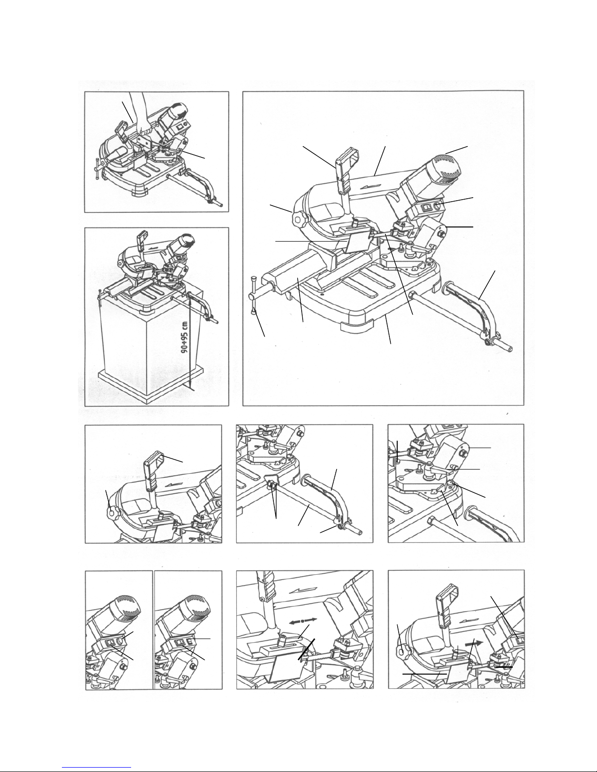
3.5 SLIDING BLADE GUIDE (Fig.8) To perform the cut, move to the front of the machine and
grip the handgrip with your right hand.
The sliding blade guide Pwith integrated protection fitted
on your sawing machine is used to perform the cut while
guiding the necessary part of the blade and fully protecting
the part not used in the cutting process.
Keep your left hand away from the cutting area and on
no account try to reach it when cutting is in process.
Using the index finger of your right hand, press the run
button A(Fig.4) and gradually lower the machine body
until it comes lightly into contact with the part to be cut.
Slacken the knobs Qand slide the blade guide P so as to
move it closer to or further from the part to be cut, as
shown in the figure. Now begin to apply gradual pressure on the part and
compete the cut.
ATTENTION : If this adjustment is not done, the part of
the blade not used in the cutting process will be
exposed and this will create an extra risk of contact,
besides altering the quality of the cut.
Always release button A between one cutting
operation and another, while you are positioning the
part. Do not try to block it or alter its functional
characteristics in any way.
Electronic version
3.6 BEARINGS BLADE GUIDE (Fig.9) If the machine suddenly stops after numerous
consecutive cuts, do not be alarmed. The heat
protector device of the motor has been activated,
breaking the power supply when the temperature of
the coils reaches the threshold limit defined by the
insulation class, to prevent damage to the motor.
The blade-auide on the outside of the sawing machine are
eccentric and adjustable so as to simplify blade
replacement and to keep it guided as its best.
They must always touch the blade slightly, so that they
rotate when the blade passes, but must not be completely
locked. In this case, release the button A and wait for
automatic reset which usually takes place after a few
minutes.
In order to approach or remove the eccentric bladeguide,
gently turn the head of the screws S using a 10 mm.
Wrenches key. Your sawing machine is equipped with an electronic
speed governor which also includes a motor
protection function obtained by means of an
amperometric limiter. In this way it can not absorb an
amount of current greater than the set one, expressed
by the maximum value of absorption (see 2.5).
4.0USE
4.1 RUNING IN THE BLADE
If the correct running in procedure is not performed,
the blade’s cutting precision may be irreparably
compromised. If the limiter trips while the machine is in operation,
slightly decrease the cutting pressure in addition, this
enables to safeguard the blade life and performance
and to obtain always a sharp and clean cut.
To obtain the best performance, the bi-metal blades fitted
on your sawing machine must be run in for a short period.
For this reason the first two or three cuts should be done
where possible on a solid piece D.40-50 mm, using a very
slight pressure on the blade, and gradually increasing
pressure in subsequent cuts.
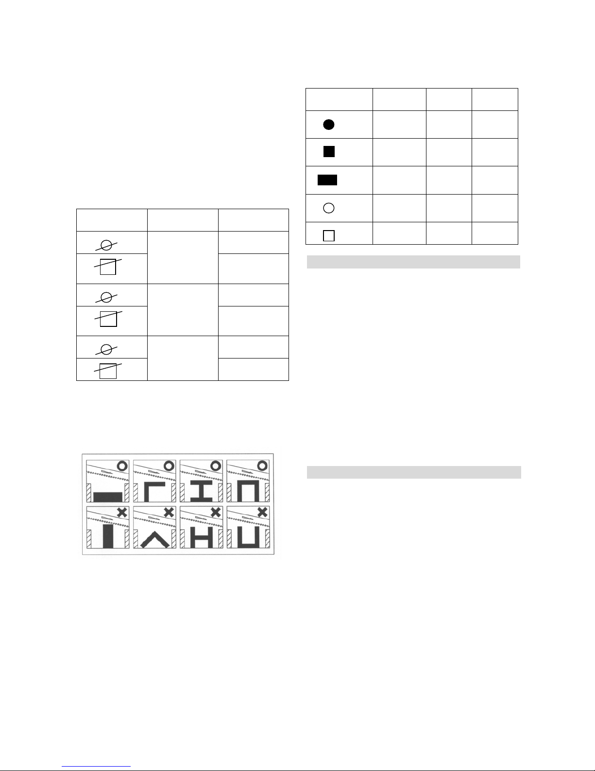
4.3 replacing the blade (Fig.9)
When you perform this operation, always wear
protective gloves to avoid contact with the teeth of the
blade.
To gauge the correct pressure in normal operating
conditions defined by this manual (see cutting table),
consider for example that the first cut on solid steel (eq.
C40) D.50 mm should be done in about 4 minutes. -check that the main switch D is at position O;
-slacken the handle Qand slide the blade guide P as far
as it will go, following the direction on the arrow (Fig.8);
After running-in , the same piece may easily be cut in
about 2 minutes. If the running-in process is done correctly,
the finish and precision of the cut will be of better quality
and the blade will last longer.
-remove the protective casing unscrewing the four screws;
-slacken the blade tension, turning the handwheel B in a
anti-clockwise direction;
-using a 10mm. Spanner, slacken the exagonal nuts Ron
the two blade guides on the outside of the blade (Fig.9);
4.2 WORKING(Fig.7) -with the same spanner gently turn the head of the screws
on the same blade-guide in a anti-clockwise direction so
as to move the bearings far enogh away from the blade
to enable you to extract it easily from the guides ;
Two speed version
Push the green button “1”of the main switch D to anable
machine operation.
Electronic version -extract the blade first from the guides and then from the
rubber coated pulleys;
Turn the main switch Dto position 1 :in doing the switch
comes on and the machine is ready for operation. -insert the new blade first between the guides and then
onto the rubber coated pulleys, with the teeth facing as
showed in picture 9;
Before starting any cutting operation, check that all
the protections are complete and in the correct
position. -put the blade under tension again as described in point
3.1 and reposition the two outer blade guides in slight
contact with the blade, turning the head of the screws S
Once you have completed all the procedures and
operations described so far, you may start the working
processes.
5

4.6 CUTTING TABLE
in a clockwise direction;
-lock the two exagonal nuts Ragain; PART RECCOMENDED CUTTING
SPEED RECCOMENDED
-replace the protective casing, being careful to insert the
blade between the straps of the protection T; DIMENSIONS TOOTHING CUTTING TIMES
( mm ) ( tooth for inch ) ( m/min ) ( min. sec. )
0’ 40”
60
8/12
30
-reposition the blade guides Pin the correct position for the
next cut.
4.4 CUTTING CAPACITY
The table below specifies the cutting capacity at 0 and 45
degrees which may be obtained in normal conditions of
use described in this manual and without placing any other
object between the jaws of the clamp.
SECTION ANGLE CUTTING
CAPACITY
122 mm
0 degrees 122 mm
95 mm
-45 degrees 95 mm
63 mm
-60 degrees 63 mm
4.5 CORRECT POSITIONING OF THE PIECE IN THE
CLAMP
The pieces to be cut should be fitted directly between the
jaws without adding other objects.
ATTENTION : Never hold the pieces to be cut in your
hand.
When the pieces to be cut are profiled sections, flat pieces
or special shapes, refer to the examples shown in the
figures.
If the thickness of the profiled section is to be very thin, an
outline should be fitted which copies the profile inside the
profiled section itself to stop it being crushed between the
jaws.
50
85 6
6 60
60 2’ 00”
5’ 00”
1’ 10”
60
8/12
30
50
85 6
6 60
60 2’ 10”
8’ 00”
1’ 10”
60
8/12
25x35
40x50
85x105 6
6 60
60 2’ 30”
11’ 00”
0’ 05”
80
18
30xs.1
40xs.2
50xs.5 14
8/12 80
80 0’ 15”
0, 50”
30xs.1 18 80 0’ 10”
50xs.2 14 80 0’ 30”
5.0 ACCESSORIES
5.1 CHOISE OF BLADE
Your sawing machine is equipped with a bi-metal blade
measuring 1440 * 13 * 0.65 mm with variable toothing 10t
teeth per inch, for use in the majority of cuts possible with
this machine.
For special requirements (see cutting table point 4.6), for
example, for cutting large solid sections or profiled
sections or corner pieces of small thickness, there are also
blades avail-able with 6, 10, 14 or 18teeth per inch.
MATERIAL: M42 (acciaio per molle + acciaio HSS)
EXTENSION: mm 1440
HEIGHT: mm13
THICKNESS: mm 0.65
TOOTHING: standard 10 optional 6- 14 –18 –10-8/12
6.0 MAINTENANCE
6.1 REGULAR MAINTENANCE
The operations of ordinary maintenance, which may also
be performed by non-specialist personnel, are all
described in the previous sections and here below.
1.Before performing any maintenance operation,
disconnect the machine electric plug from the wall
outlet.
2.During maintenance operations, always wear personal
protection (safety goggles and gloves).
3.Remove the processing residues from the cutting area
and the blade guides whenever necessary.
You are advised to use a suction device or a brush.
Do not use jets of compressed air.
4.If you do not intend to use the sawing machine for a long
time, clean it and put it in a dry place if possible.
In these cases it is advisable to slacken off the blade so
that it is not kept tight for no reason.
6

6.2 ASSISTENCE
Should it be necessary to call qualified personnel for
operations of extraordinary maintenance, or in the case of
repairs, under guarantee or at a later date, you should
always contact an authorized service center or the factory
directly. If there is no service centre in your area.
6.3 DISPOSAL OF THE MACHINE
Once its operating activity is finished, the disposal of the
machine must take place through a ormal collection and
disposal Center for industrial waste.
7.0TROUBLESHOOTING
PROBLEMS CAUSES SOLUTIONS SUGGESTED
Specialized personnel should check
the machine ; do not attempt to repair
the motor by yourself.
The motor does not work. Defective motor, power cable or plug.
Check fuse integrity and replace, if
necessary.
Blown electric panel fuses.
Check for voltage in the mains system.
No voltage in the mains system. Release the run button and wait a few
minutes for the overload cutout to
reset.
The overload cutout has tripped.
Check that motor air intakes are clear.
Overload cutout tripped. Motor overheating. Perform the cut on the piece at the
correct pressure.
Motor overload caused by excessive
cutting pressure. Specialized personnel should check
the machine ; do not attempt to repair
the machine by yourself.
Motor breakdown.
Inaccurate cutting angle at
90∘- 45∘. The setting of the H and K retainers
(point 3.3) is inaccurate. Set the retainers by unloosening the
fastening screws and re-positioning
them.
Decrease cutting pressure.
Inaccurate cut squaring. Excessive cutting pressure (on pipes
and section bars).
Check the cutting parameters (blade
toothing, cutting speed ) in the cuts
table (point 4.6).
Incorrect blade toothing in relation to
the piece to cut.
Check blade-guide adjustment (points
3.5 and 3.6).
Incorrect adjustment of the eccentric
and sliding blade-guides. Check piece positioning and clamping
in the vice (point 4.5).
Incorrect cutting speed in relation to the
piece to cut. Check blade tension (point 3.1).
The piece is wrongly positioned in the
vice.
Poor blade tension. Check the cutting parameters (blade
toothing, cutting speed ) in the cuts
table (point 4.6).
Cut finish is coarse or corrugated. The blade is worn or its toothing is not
right for the thickness of the piece
being cut. Decrease cutting pressure.
Excessive cutting pressure.
Check eccentric blade-guide
adjustment (point 3.6).
The blade tends to protrude from the
guides. Excessive blade tension.
Specialized personnel should check
the pulleys and replace them if
necessary.
Incorrect eccentric blade-guide
adjustment.
Never use any type of lubricant or
coolant for the cutting operations;
specialized personnel should check
and, if necessary, replace the pulleys.
Excessive wear of the pulley rubber
linings.
The blade slips on the pulleys, caused
by oil or grease required for cutting
operations.
Check blade tension (point 3.1).
7

8

9

10

11

CODE NO PART NO DESCRIPTION SPECIFICATION QTY NOTE
1 125002 Body Frame 1
2 HD901 Nut M6 4
3 HW104 Spring Washer M6 4
4 111018 Guide Bracket 1
5 111009 Washer 4
6 CA6072RS Bearing 607-2RS 8
7 111016 Eccentric Shaft 4
8 111020 Knob 1
9 125025 Adjustable Bracket (Front) 1
10 CA6242RS Bearing 624-2RS 2
11 111096 Pin ∮4x19.8L 2
12 111031 Washer 4
13 111024A Blade Cover(Front) 1
14 HS466 Hex. Socker Headless Screw M8x8L 2
15 111067 Carriage Screw M6x30L 1
17 HS610 Flat Cross Head Screw M5x10L 8
18 111060 Bracket 2
19 HW004 Washer M6 2
20 HW005 Washer M8 2
21 111014 Knob 1
22-1 ET1244 Limit Switch 1
23 125048 Connecting Tube 1
24 125050A Blade 1440x13x0.65-8/12T 1
25 125017 Fixed Shaft 1
25-1 HT004 Flat Cross Head Screw M6x15L 3
26 111004 Drive Wheel 1
27 111072 Washer 1
27-1 111072A Washer 21.8*15.2-1 1
28 HE506 Hex. Head Screw M5x10L 4
29 125036 Blade Back Cover 1
32 111022 Tension Bracket 1
33 111028 Press Cake 4
34 HT002 Flat Cross Head Screw M5x16L 4
35 111056 Spring 1
36 111017 Spring 1
37 111013 Bolt 1
42 111012 Shaft 1
45 E095212 Cable 1
46-3 HS815 Cross Round Head Screw Ø3.5X35L 2
46-4 111085 Motor Cover 1
PARTS LIST
MODEL NO. 125
12

CODE NO PART NO DESCRIPTION SPECIFICATION QTY NOTE
PARTS LIST
MODEL NO. 125
46-5 HS816 Cross Round Head Screw Ø4X15L 2
46-7 111088A Separator 1
46-8 111088 Fan 1
46-9 111087A Bracket 1
46S2 M085 Motor 220V 1
46S2 M085-2 Motor 110V 1
46-1 111084 Brush 2
46-2S 111055AS Motor Rotor Assembly 1
111055 Motor Rotor Shaft 1
111055B Motor Rotor 1
46-6S ET2515 Driver Assembly CF-16(220V) 1
46-6S ET2521 Driver Assembly CF-16(110V) 1
111090A Bracket 1
57 HS219 Hex. Socket Head Screw M5x16L 4
58 CAHK0609 Bearing HK0609 2
59 111032 Washer 3
60 111005 Gear-A 1
61 111044 Bushing 1
62 111006 Gear-B 1
63 111033 Washer 1
64 CAHK0810 Bearing HK0810 1
66 CA6272RS Bearing 627-2RS 1
67 111007 Gear-C 1
68 CA6202LLU Bearing 6202LLU 1
92 HW105 Spring Washer M8 6
93 HS242 Hex. Socket Head Screw M8x20L 6
94 111059 Coaster 4
95 HW006 Washer M10x20x2t 2
96 HB804 Nut M10 1
97 HS935 Carriage Screw M10x33L 1
98 HN010 Hex. Nut M14xP1.5 2
99 111057 Distance Set Rod 1
100 111058 Distance Set Bracket 1
100-1 111097 Plum handle 1
100-2 HS036 Hex. Head Screw M6x30L 1
101 111045 Angle Margin 2
102 HS527 Cross Round Head Screw M6x10L 2
104 125033 Degree-Meter 1
105 111116 Rivet ∮3.3X6L 2
107 HS263 Hex. Socket Head Screw M10x45L 1
13

CODE NO PART NO DESCRIPTION SPECIFICATION QTY NOTE
PARTS LIST
MODEL NO. 125
108 HN004 Hex. Nut M6 1
109 HS425 Hex. Socker Headless Screw M6x25L 1
110 111039 Knob 1
111 HW030 Washer M10x27x2t 1
112 111027 Knob W/Shaft 1
114 111026 Position pin 1
115 HE010 E Retaining Ring E7 1
116 111023 Spring 1
119 111003N Swivel Arm 1
120 125018 Washer 1
121 HB808 Nut AN02 1
122 E195312J Power cable 1
123 111091 Cable Setting Nut 1
124 HS817 Cross Round Head Screw Ø4X20L 2
126S1 111093S1 Switch Assembly 1
126-1 111093N Cover 1
126-2 111093A Cover 2Speed 1
126-3 HS822 Cross Round Head Screw Ø4.0X40L 3
126-4 ET1247 2 Switch 3P 1
126-5 ET1156 ON/OFF Switch KJD-17(220V) 1
126-6 HS519 Cross Round Head Screw M5X10L 3
126S2 111093S2 Switch Assembly 1
126-2 111093C Cover 1
126-3 HS815 Cross Round Head Screw Ø3.5X35L 3
126-4 ET2147 Revolution Knob 1
126-5 ET1156 ON/OFF Switch KJD-17(220V) 1
126-7 111134 Speed plate 1
134 111066 Cable Clamp 6
135 HB803 Hex. Nut M8 2
136 111071 Clamp 1
137 111072 Washer 1
138 CA60022RS Bearing 6002-2RS 2
139 HT004 Hex. Socket Flat Head Scvew M6x16L 1
140 111004F Idler Wheel 1
141 111040B Swivel Base 1
142S 125041AS Vise Base Assembly 1
142-3 111051A-2 Bushing 1
142-4 111051A Leadscrew 1
142-5 125041 Vise Base 1
142-6 125042 Vise Jaw Bracket 1
14

CODE NO PART NO DESCRIPTION SPECIFICATION QTY NOTE
PARTS LIST
MODEL NO. 125
142-8 111068 Cover 1
142-9 HW104 Washer M6 1
142-10 HS227 Hex. Socket Head Screw M6x5L 1
160 HW306 Star Washer M5 1
161 HS519 Cross Round Head Screw M5x10L 1
15


SERIAL No.:
PLEASE WRITE DOWN THE SERIAL NO. ON THIS BLOCK FROM THE NAME
PLATE AFTER YOU RECEIVE THIS MACHINE.
ADDRESS:
Table of contents
Popular Saw manuals by other brands

Craftsman
Craftsman 172.10850 owner's manual

Panasonic
Panasonic EY45A5 Service manual

Norfield
Norfield 1020 Operation manual

Makita
Makita 5044KB instruction manual

Whittemore Enterprises Inc.
Whittemore Enterprises Inc. Push Cut TPLO operating manual

Chicago Electric
Chicago Electric 94488 Assembly and operating instructions