Installation
CAUTION:
Theinstallationmust be
conductedbyaqualifiedtechnician.
ReceivingAndHandling
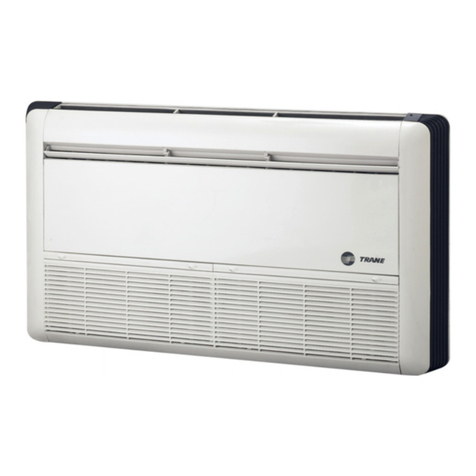
Trane HFCF Fan Coilunitsarepackagedin
individualcartons formaximumprotection
duringshipment, as wellasforeasy handling
and storage onthe jobsite.
Toprotect againstloss fromin-transit damage,
completethe followinguponreceiptoftheunits:
1. Inspect individualpieces of the shipment
beforeaccepting it.Checkforrattles, bent
cornersoncartons orothervisible
indicationsof shipping damage.
2.If acarton has apparent damage, openit
immediatelyandinspect the contents
beforeaccepting the unit.Donot refusethe
shipment.Makespecificnotations
concerning thedamageonthe freight bill.
Checkthe unit casing, fan rotation, coils,
drainpan, filtersand alloptions.
3.Inspect the unit forconcealeddamage
beforeit isstored and as soon as possible
afterdelivery.
4.Donot removedamagedmaterialfromthe
receivinglocationif possible.It isthe
receiver'sresponsibilitytoprovide
reasonableevidence that concealed
damagewas not incurred afterdelivery.
5.If concealed damageisdiscovered, stop
unpacking theshipment.Retainallinternal
packing and cartons.
Takephotos of the
damaged materialif possible.
6.Notifythe carrier'sterminalof damage
immediatelybyphone and mailif any
damageisfound.Request animmediate
joint inspectionof the damagebythe
carrierandconsignee.
7.Notifythe
Trane sales representativeof
the damage and arrange forrepair. Donot
repairthe unit yourself, however, until
damageisinspectedbythecarrier's
representative.
InstallationConsiderations
Forproperinstallation andoperation, check
eachof the followingbeforemountingthe
units:
1.Allowadequatespace fortheunit and free
airorservice clearancesreferenceFigure2.
SeeFigures4, 5and 6forgeneralunit
dimensions.Forservicingand routine
maintenance, provide accesstotheunit
through removablepanelsinthe ceiling.
2.Beforeinstalling any unit makesureproper
preparation hasbeenmadeat eachunit
location forpipingand electrical
connections.
3.Checkthat the supportingstructureis
strong enough tosupport unit weights, as
given on Figures4, 5and 6.
4.All unitsmust bemountedLEVELto
assureproperdrainageandoperation.
5. Ducting connected tounits(where
applicable)shouldnotexceedthe external
staticpressureratingof the unit.
6.Condensateprotection forthe chilled water
valves andpiping must beprovided by
installer. Adrainpanextension providedby
installershouldbelocatedunderthe valves
orelse the valves and piping shouldbe
thoroughlyinsulated.
7.Unitswithvalvepackage areequipped
withlongdrainpanwhichcancarrythe
condensationfromwatervalves.
Insulationofvalvepackageisnotrequired.
Mounting
The
TranemodelHFCF unitsaredesigned to
be suspendedfromthe ceilingon 3/8-16
threadedrods furnished bythe installer. Holes
areprovidedat the topof the unit, seeFigures
4, 5and6forcutout dimensionsandlocations.
Toinstall the
Trane modelHFCF, complete
the following:
6
1.Installthe suspension rods orother
suspensiondevices whichmustbe
providedbythe installer.
2.Put the upper
W3/8nutsand
W3/8lock
washersonsuspension rodstoprevent
unit fromupwardtilting duringunit
operationorduct installation, asshownon
Figure2
TypicalInstallation.
3. Hoist theunit intoposition. SeeFigures4, 5
and 6forunitweights.
4.Put onthe lower
W3/8lockwashersand
then
W3/8nutstosecuretheunit, as
shownonFigure2
Typical Installation.
5.Leveltheunit casing toavoidpoor
condensatedrainagebyadjustinglower
nutsup/down, and thentightentheupper
nuts.
Note:Level theunitbychecking onthe
unit casing.Donotuse thecoil ordrain
panforleveling as theyarepitchedto
provide properdrainage.
DuctConnections
Minimum24 gaugegalvanizedsheet metal
duct (supplied bytheinstaller) canbe
attached toduct collarsprovided at theunit
airoutlet and inlet, seeFigures4, 5and6
forduct collardimensions.
Toattach, slipthe
duct overtheoutlet collarand fastenthe
duct and collartogetherwithscrews.Filed-
suppliedtransitionfittings shouldbeusedin
installations whereunit duct collarsdo not
match dischargeair-grillecollars.
One approaches canbeusedtoattachan
AirSupplyChamberand flexibleducts.
Theapproachistosliptheduct overthe unit
outlet collarandthen fastentheduct and
collartogetherwithscrewsorrivets, as
shownon Figure3Duct
Work-A.
Areturnduct can be attached tothe return
aircollarprovided at theunit.
Toattach, slip
the returnduct overthereturnaircollarand
fastenthe duct andcollartogetherwith
screws.
HFCF-SVX01A-EN
