67
32
May 2012 © 2012 Trane RT-SVU04F-EN
All rights reserved
Model 12½ through 25 Ton Packaged Gas/Electric
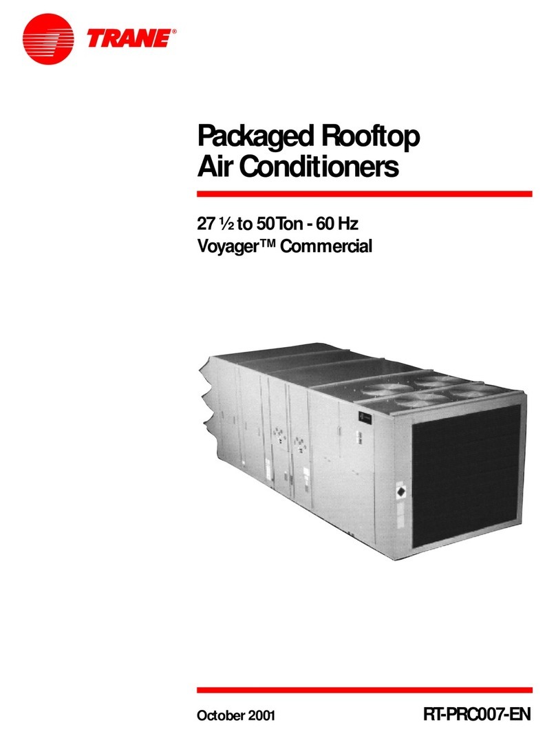
27½ through 50 Ton Packaged Gas/Electric
SAFETY WARNING
Only qualified personnel should install and service the equipment. The
installation, starting up, and servicing of heating, ventilating, and air-
conditioning equipment can be hazardous and requires specific
knowledge and training. Improperly installed, adjusted or altered
equipmentbyanunqualifiedpersoncouldresultindeathorseriousinjury.
When working on the equipment, observe all precautions in the literature
and on the tags, stickers, and labels that are attached to the equipment.
4 5
1
Owner Manual
Packaged Rooftop Air Conditioners
Voyager™ Gas/Electric
For Servicers and Owners Use
Cautions, Warnings and Notices
Important: Environmental Concerns! Scientific research has shown
that certain man-made chemicals can affect the earth's naturally occurring
stratospheric ozone layer when released to the atmosphere. In particular,
several of the identified chemicals that may affect the ozone layer are
refrigerants that contain Chlorine, Fluorine and Carbon (CFCs) and those
containing Hydrogen, Chlorine, Fluorine and Carbon (HCFCs). Not all
refrigerants containing these compounds have the same potential impact
to the environment. Trane advocates the responsible handling of all
refrigerants-including industry replacements for CFCs such as HCFCs and
HFCs.
Important: Responsible Refrigerant Practices! Trane believes that
responsible refrigerant practices are important to the environment, our
customers, and the air conditioning industry. All technicians who handle
refrigerants must be certified. The Federal Clean Air Act (Section 608) sets
forththerequirementsforhandling,reclaiming,recoveringandrecyclingof
certain refrigerants and the equipment that is used in these service
procedures. In addition, some states ormunicipalities mayhave additional
requirements that mustalso be adheredto for responsible management of
refrigerants. Know the applicable laws and follow them.
Indicates a potentially hazardous situation which, if not avoided, could
result in death or serious injury
Indicates a potentially hazardous situation which, if not avoided, could
result in minor or moderate injury. It may also be used to alert against
unsafe practices.
NOTICE
Indicates a situation that could result in equipment or property-damage
only accidents. Overview of Manual
One copy of this document ships inside the control panel of each unit and
is customer property. It must be retained by the unit’s maintenance
personnel.
Your combination gas heating/cooling unit is designed to provide comfort
all year long with safe, efficient, trouble-free operation. It is important that
you understand how to operate and maintain your unit to keep it operating
safely and efficiently. This manual will acquaint you with these important
procedures.
Model Number Description
All products are identified by a multiple-character model number that
precisely identifies a particular type of unit. Its use will enable the
owner/operator, installing contractors, and service engineers to define the
operation, specific components, and other options for any specific unit.
When ordering replacement parts or requesting service, be sure to refer to
the specific model number and serial number printed on the unit
nameplate.
Personal Protective Equipment Required!
Installing/servicing this unit could result in exposure to electrical,
mechanical and chemical hazards. Before installing/servicing this unit,
technicians MUST put on all Personal Protective Equipment (PPE)
recommended for the work being undertaken. ALWAYS refer to
appropriate MSDS sheets and OSHA guidelines for proper PPE. When
working with or around hazardous chemicals, ALWAYS refer to the
appropriate MSDS sheets and OSHA guidelines for information on
allowable personal exposure levels, proper respiratory protection and
handling recommendations. If there is a risk of arc or flash, technicians
MUST put on all necessary Personal Protective Equipment (PPE) in
accordance with NFPA70E for arc/flash protection PRIOR to servicing the
unit. Failure to follow recommendations could result in death or serious
injury.
Inspection
• Unpack all components of the kit.
• Checkcarefully foranyshippingdamage.Ifanydamageisfounditmust
be reported immediately and a claim made against the transportation
company.
• Visually inspect the components for shipping damage as soon as
possible after delivery, before it is stored. Concealed damage must be
reported within 15 days.
• If concealed damage is discovered, stop unpacking the shipment.
• Do not remove damaged material from the receiving location. Take
photos of the damage, if possible. The owner must provide reasonable
evidence that the damage did not occur after delivery.
• Notify the carrier’s terminal of damage immediately by phone and by
mail. Request an immediate joint inspection of the damage by the
carrier and the consignee.
Important: Do not attempt to repair any damaged parts until the parts are
inspected by the carrier’s representative.
Important Safety Instructions
General Safety Instructions
• Do not store combustible materials, gasoline or other flammable
vapors and liquids near the unit.
• Should overheating occur, or the gas supply fail to shut off, shut off the
manualgasvalvetothefurnacebeforeshuttingofftheelectricalsupply.
• Do not use this furnace if any part has been under water. Immediately
call a qualified service technician to inspect the furnace and to replace
any part of the control system and any gas control system and any gas
control which has been under water.
• Never perform any maintenance procedures until the electrical power
and/or gas supply to the unit has been turned off.
• Never remove any panels from the unit while it is operating.
• Never remove panels or parts from this unit that are not discussed in
this manual.
• Never cover the unit, since it is designed to operate year-round.
• The furnace area must be kept clear and free of combustible materials,
gasoline and other flammable vapors and liquids.
• Forproperandsafeoperationthefurnaceneedsairforcombustionand
ventilation. Do not block or obstruct air openings on the furnace, air
openings communicating with the areas in which the furnace is
installed, and the spacing around the furnace.
Atinstallationandthebeginningofeachheatingseason,aqualifiedservice
technician should examine the furnace to ensure:
• All flue products carrying areas external to the furnace, (i.e., chimney,
vent connector, etc.), are clear and free of obstructions.
• The physical support of the furnace is sound and without sagging,
cracks, gaps, etc., around the base so as to provide a seal between the
support and the base.
• There are no obvious signs of deterioration of the furnace.
Safety Instructions!
Failure to follow instructions in this section could result in death, serious
injury, and property damage.
Safety Instructions Before Operating the Unit
• This appliance does not have a pilot. It is equipped with an ignition
device which automatically lights the burner. Do not try to light the
burner by hand.
• BEFORE OPERATING smell all around the appliance area for gas. Be
sure to smell next to the floor because some gas is heavier than air and
will settle on the floor.
What To Do If You Smell Gas
• Do not try to light any appliance.
• Donot touchanyelectricswitch;donotuse any phonein your building.
• Immediatelycallyour gassupplier from a neighbor’sphone.Followthe
gas supplier’s instructions.
• If you cannot reach your gas supplier, call the fire department.
Temperature Control Devices
Room thermostats and zone sensors are delicate temperature control
devices.
Thermostats’ main function is to energize and de-energize the heating or
cooling circuit to maintain the temperature setting you select.
Zone sensors’ main function is to sense the room temperature to allow the
unit controls to activate the heating and cooling functions to maintain the
temperature setting you select.
Many thermostats and zone sensors contain a room thermometer to
indicatetheapproximateroomtemperature,andatemperaturescaleatthe
adjustment indicator to select the desired indoor air temperature. In
addition,mostcontrolshaveaselectormodeswitchwithHeat,OffandCool
positions, and a fan switch with On and Auto positions.
When the selector switch is positioned at Off, your unit will not operate in
either the heat or cool modes. If the selector switch is set at Heat, the unit
will automatically cycle on and off to maintain the desired temperature
setting.The unit will also operate automaticallywhen the selector switchis
positioned at Cool.
The fan selector switch can be used to operate the indoor fan continuously
by positioning it at On. When set at Auto, the fan will only operate when
required during the heating or cooling cycles.
To ensure that the thermostat or zone sensor operates properly, it must be
level and positioned to avoid the influence of such external heat sources
such as lamps, televisions or other heat producing appliances.
Air Filters
It is very important to keep the central duct system air filters clean. Be sure
to inspect them at least once each month when the system is in constant
operation.(Innewhomes, checkthefilters everyweekforthe first 4 weeks.)
See Table 1 for the required filter size(s).
Ifyouhavedisposabletypefilters,replacethemwithnew filtersofthesame
type and size. Do not attempt to clean disposable filters.
Permanent type filters can be cleaned by washing them with a mild
detergent and water. Ensure that the filters are thoroughly dry before
reinstalling them in the unit (or duct system).
Note: Itmay be necessaryto replace permanentfilters annually if washing
fails to clean the filter, or if the filter shows signs of deterioration. Be sure
to use the same type and size as was originally installed.
Table 1. Recommended filter size
Model Qty Filter Size
(L x W x D)
YS*150F 2 20 x 20 x 2
4 20 x 25 x 2
YSD155F, 180F, 175F, 210F, 240F, 250F, 300F
YHD150F
WSD150E,180E 420 x 20 x 2
20 x 25 x 2
YSH155F, 180F, 175F, 210F, 240F, 250F, 300F
YHH150F
WSH150E,180E 8 20 x 25 x 2
YHD180F, 210F, 240F, 300F
WSD240E 8 20 x 20 x 2
4 16 x 20 x 2
YHH180F, 210F, 240F,300F
WSH240E 12 20 x 20 x 2
YC*330-420 16 16 x 20 x 2(a)
(a)4” Filters are optional. Replace with same size as originally supplied.
YC*480-600 17 16 x 20 x 2(a)
1. * = Applies to both downflow and horizontal.
2. Filters not provided with 4- and 5- ton horizontal units.
