manuals.online logo
Brands
  1. Home
  2. •
  3. Brands
  4. •
  5. Trane
  6. •
  7. Heat Pump
  8. •
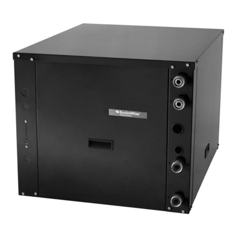
  9. Trane GEHB018 User manual

Trane GEHB018 User manual

This manual suits for next models

3

Other Trane Heat Pump manuals

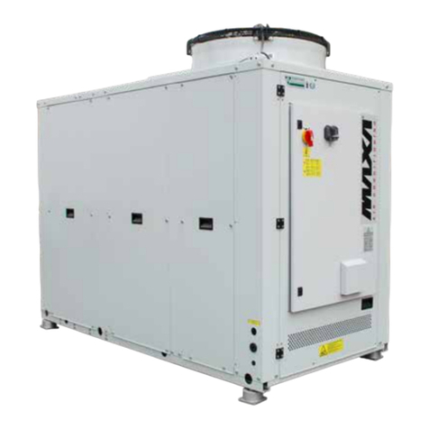
Trane MAXA i-HPV5H 0140 User guide

Trane

Trane MAXA i-HPV5H 0140 User guide
Trane 4WCC4024E1000A User manual

Trane

Trane 4WCC4024E1000A User manual

Trane 4TWB3018D Assembly instructions

Trane

Trane 4TWB3018D Assembly instructions

Trane GECA Owner's manual

Trane

Trane GECA Owner's manual

Trane 2/4WCC30 Series Assembly instructions

Trane

Trane 2/4WCC30 Series Assembly instructions

Trane 4TWR6 User manual

Trane

Trane 4TWR6 User manual

Trane A4AC3018D User manual

Trane

Trane A4AC3018D User manual

Trane 4TWR6 Assembly instructions

Trane

Trane 4TWR6 Assembly instructions

Trane A4HP4018D1000A Assembly instructions

Trane

Trane A4HP4018D1000A Assembly instructions

Trane GEH/V Series User manual

Trane

Trane GEH/V Series User manual

Trane RAUS 040 Owner's manual

Trane

Trane RAUS 040 Owner's manual

Trane 2TWB0012-036AA Assembly instructions

Trane

Trane 2TWB0012-036AA Assembly instructions

Trane 4TWX7 Series Assembly instructions

Trane

Trane 4TWX7 Series Assembly instructions

Trane 2GN Series Assembly instructions

Trane

Trane 2GN Series Assembly instructions

Trane 4WCY5024A1000A Assembly instructions

Trane

Trane 4WCY5024A1000A Assembly instructions

Trane Horizon OABE/F Installation and operating instructions

Trane

Trane Horizon OABE/F Installation and operating instructions

Trane 4YCY4024 Assembly instructions

Trane

Trane 4YCY4024 Assembly instructions

Trane 5TWX5 User manual

Trane

Trane 5TWX5 User manual

Trane CAUC-C80 Owner's manual

Trane

Trane CAUC-C80 Owner's manual

Trane DCY060F1 Guide

Trane

Trane DCY060F1 Guide

Trane Weathertron 22-5202-03-3605 Installation instructions

Trane

Trane Weathertron 22-5202-03-3605 Installation instructions

Trane UH-PRC001-EN Datasheet

Trane

Trane UH-PRC001-EN Datasheet

Trane RAUS 160-400 Owner's manual

Trane

Trane RAUS 160-400 Owner's manual

Trane 22-5213-WEB01 User manual

Trane

Trane 22-5213-WEB01 User manual

Popular Heat Pump manuals by other brands

Daikin RXL12QMVJU Service manual

Daikin

Daikin RXL12QMVJU Service manual

AIREDALE BluCube CUR092V16-1CO-0 Installation and maintenance manual

AIREDALE

AIREDALE BluCube CUR092V16-1CO-0 Installation and maintenance manual

Calyenty RBH 125 Customer's manual

Calyenty

Calyenty RBH 125 Customer's manual

GRE HPGI50 owner's manual

GRE

GRE HPGI50 owner's manual

Carrier 30XW Installation, operation and maintenance instructions

Carrier

Carrier 30XW Installation, operation and maintenance instructions

Hayward SUMHEAT HP5131DT3 Installation instructions manual

Hayward

Hayward SUMHEAT HP5131DT3 Installation instructions manual

REMKO SQW 400 Electrical wiring

REMKO

REMKO SQW 400 Electrical wiring

Sanyo SAP120FCH Service manual

Sanyo

Sanyo SAP120FCH Service manual

Daikin EHYHBH05AA Operation manual

Daikin

Daikin EHYHBH05AA Operation manual

Panasonic WH-SDF03E3E5 Design handbook

Panasonic

Panasonic WH-SDF03E3E5 Design handbook

Airxcel 45000 Series Installation, operation and maintenance instructions

Airxcel

Airxcel 45000 Series Installation, operation and maintenance instructions

Mitsubishi Electric PUZ-SWM60VAA Service manual

Mitsubishi Electric

Mitsubishi Electric PUZ-SWM60VAA Service manual

Dimplex LI 16I-TUR Installation and operating instruction

Dimplex

Dimplex LI 16I-TUR Installation and operating instruction

Carrier WSHP Open v3 Integration guide

Carrier

Carrier WSHP Open v3 Integration guide

Mitsubishi Electric EHSE-YM9EC Service manual

Mitsubishi Electric

Mitsubishi Electric EHSE-YM9EC Service manual

TGM CTV14CN018A Technical manual

TGM

TGM CTV14CN018A Technical manual

Carrier 38MGQ Series installation instructions

Carrier

Carrier 38MGQ Series installation instructions

Kokido K2O K880BX/EU Owner's manual & installation guide

Kokido

Kokido K2O K880BX/EU Owner's manual & installation guide

manuals.online logo
manuals.online logoBrands
  • About & Mission
  • Contact us
  • Privacy Policy
  • Terms and Conditions

Copyright 2025 Manuals.Online. All Rights Reserved.

Crankcase Heater
Wiring
For KIT14712 and KIT14718
Models: GEHB018, GEVB018, KIT14712, KIT14718
Installation
PART-SVN100A-EN
2 Crankcase Heater Wiring PART-SVN100A-EN
Installation
Literature change history
PART-SVN100A-EN (October 2006) manual first release.
Warnings and Cautions
Instructions
 WARNING
Hazardous Voltage w/Capacitors!
Disconnect all electric power, including remote disconnects and discharge all
motor start/run capacitors before servicing. Follow proper lockout/tagout
procedures to ensure the power cannot be inadvertently energized. Verify
with an appropriate voltmeter that all capacitors have discharged. Failure to
disconnect power and discharge capacitors before servicing could result in
death or serious injury.
Note: For additional information regarding the safe discharge of capacitors,
see PROD-SVB06A-EN or PROD-SVB06A-FR.
This KIT includes a relay, wiring assembly, and crankcase (sump) heater. The
following information and wiring digram shown in Figure 1 (p. 3) should be
used to install this device.
HTR06811 - Crankcase heater, 30 Watt, 5.07” diameter, 208/230 Vac or
HTR06851 - Crankcase heater, 30 Watt, 5.07” diameter, 265 Vac
and
RLY01357 - DPDT relay, 24 Vac coil 50/60 HZ, 3 A 277 Vac pilot duty contacts
WIR004682 - Wire harness for adding crankcase heater
1Turn off all power sources to the unit. Follow proper lock out and tag out
procedures.
2Install mechanical components, heater and relay.
NOTICE: Warnings and Cautions appear at appropriate sections
throughout this literature. Read these carefully.
WARNING: Indicates a potentially hazardous situation which, if not
avoided, could result in death or serious injury.
 CAUTION: Indicates a potentially hazardous situation which, if not
avoided, may result in minor or moderate injury. It may also be used to
alert against unsafe practices.
CAUTION: Indicates a situation that may result in equipment or prop-
erty-damage only accidents.
© 2006 American Standard Inc. All rights reserved
PART-SVN100A-EN Crankcase Heater Wiring 3
Installation
3Connect new blue wire 3 to incoming compressor power and terminal 1
on the new relay
4Connect new black wire 4 to the second incoming compressor power and
terminal 4 on the new relay.
5Connect crankcase heater wires to terminals 2 and 5 on the new relay.
6Connect the new relay coil (double tab terminals) to the terminals 4 and 6
on the customer terminal block. Use wires yellow 1 and orange 2.
Figure 1. Crankcase heater wiring diagram
Crankcase Heater
Relay
Wire relay terminals 1 & 4
to the compressor
contactor incoming power
Connect heater ground wire
to the unit chassis ground
Connect Relay coil leads to
terminal 4 & 6 on the
customer terminal block. The
relay coil terminals have
double tabs.
Connect heater leads
to relay terminals 2 & 5
Installation
Tr a n e
A business of American Standard Corporation
www.trane.com
For more information, contact your local Trane
office or e-mail us at comfor[email protected]
Trane has a policy of continuous product data and product improvement and reserves the right to
change design and specifications without notice. Only qualified technicians should perform the
installation and servicing of equipment referred to in this bulletin.
Literature Order Number PART-SVN100A-EN
File Number SV-SP-PART-SVN100A-EN-1006
Supersedes New
Stocking Location Electronic only