manuals.online logo
Brands
  1. Home
  2. •
  3. Brands
  4. •
  5. Trane
  6. •
  7. Heat Pump
  8. •
  9. Trane SSC-APG002-EN User guide

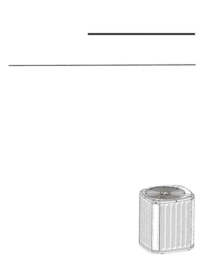
Trane SSC-APG002-EN User guide

Application Guide
SSC-APG002-EN
Low Outdoor Ambient Operation
UnitMounting
Minimum Clearances
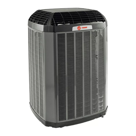
Trane XR Style Outdoor Models
Trane XR Style Condensing Units and Heat Pumps
© Trane 2015Page 2 SSC-APG002-EN
ISSUEDBY:
ProductApplicationEngineeringDepartment
TraneacompanyofIngersollRand
Tyler,Texas
Thepurposeofthisbulletin is toprovideapplicationcriteriaas related totheTrane XR stylecondensing
unitsandheatpumpunits.
Thisbulletindiscusses:
I. Termsanddefinitions
II. Offseasoncoolingoperation
III. Compressorcrankcaseheatrequirements forsplitheatpump systems.
IV. Unitmounting
V. Minimumoperatingclearances
VI. Clearancefromvents
VII. Nameplateelectricaldata
POSITIONSTATEMENT:
Trane hasalwaysrecommendedinstallingTraneapproved,matchedindoorandoutdoor systems.
Thebenefitsofinstallingapprovedmatchedsytemsaremaximumefficiency,optimumperformance,and
bestoverallsystemreliability
WARNING – Indicates a potentially hazardous situation which, if not avoided,
could result in death or serious injury.
CAUTION – Indicates a potentially hazardous situation which, if not avoided,
may result in minor or moderate injury. It may also be used to alert against unsafe
practices.
CAUTION – Indicates a situation that may result in equipment or property-damage-
only accidents.
WarningsandCautionsmayappearthroughoutthismanual.Readthesecarefully.
© Trane 2015Page 3 SSC-APG002-EN
All 2.5 to 5 ton three phase split system cooling units and heat pumps are shipped from
the factory with compressor crankcase heat. Three phase compressor do not require
start capacitors or start relays.
CCHT - Compressor Crankcase Heater, sometimes called a compressor sump heater.
This device is designed to warm the compressor crankcase (or sump) in order to prevent
or deter refrigerant migration during the compressor off cycle. Compressor crankcase
heaters are required for low ambient cooling operation.
TXV - Thermostatic Expansion Valve. This is a type of refrigerant flow control device
designed to maintain constant superheat throughout the operating envelope. For low
ambient cooling applications, a non-bleed TXV is required.
Bleed TXV: This type of TXV will allow the refrigerant pressures between the high side
and low side to equalize through the valve during the off cycle.
Non Bleed TXV: This type of TXV will not allow the refrigerant pressures between the
high side and low side to equalize through the valve during the off cycle. When using this
type of valve on single phase units with reciprocating style compressors, compressor
start components are required. Check product data specifications for most current infor-
mation.
Head pressure controller -Adevice that is field installed on a condensing unit or heat
pump designed to maintain system head pressure that will allow safe system operation
without indoor coil icing in colder outdoor ambients. The BAYLOAM*** will cycle the
condenser fan motor in order to achieve adequate operating head pressure. The control
isadjustable.
Evaporator Defrost Control -Adevice that is field installed on the system’s indoor coil
in order to prevent the system from running during the cooling cycle when the indoor coil
approaches or reaches a temperature in which frost will form on the coil surface. When
the indoor coil approaches a safe temperature for cooling operation, the control will close
and allow the outdoor unit to restart. This controller makes and breaks the control volt-
age to the condensing unit.
Quick Start Component - This component may be factory installed or offered as a field
installed accessory ( BAYKSKT***). A quick start kit consist of a capacitor with a high
microfarad rating and a potential relay. It is installed so that the start capacitor is wired in
parallel with the compressor’s run capacitor. Prior to start-up the potential relay contacts
are closed, therefore placing the start capacitor in the compressor circuit, as the com-
pressor motor reaches operating speed, electrical current flows through the potential
relay’s coil and the the relay contacts are opened, thus taking the start capacitor out of
the system until the next compressor start up.
Definitions and information:
Three phase products:
Section I - Terms and Definitions:
Section II –Off Season Cooling Operation
Trane outdoor units may be operated in the cooling mode to 55°F outdoor ambient as shipped
from the factory when applied with an indoor TXV. Where required, these units with
appropriate accessories may be applied to operate at outdoor temperatures below 55°F.
Unit requires a compressor crankcase heater and start accessory only if it is not factory installed.
Compressor Crankcase Heaters:
Reciprocating Compressor: BAYCCHT300
Large Scroll Compressor: BAYCCHT301RES
Small Scroll Compressor: BAYCCHT302RES
As noted in the above table, systems may be operated lower than 55°F by applying the
BAYLOAM103 or BAYLOAM107 and other accessories. The BAYLOAM*** controller cycles
the outdoor fan motor as needed to maintain liquid line temperature as set by the DIP switches
located on the control. There is no need to change the outdoor motor on approved products since
the controller does not vary the frequency to the motor. However the BAYLOAM*** CANNOT
be applied to those model tonnages with a variable speed condenser fan motor.
55°F - 30°F 55°F - 30°F 55°F - 30°F 55°F - 30°F 30°F - 20°F or 30°F - 0°F see lowest approved OD ambient
Air
Conditioner
Heat Pump
55 deg F. As
Manufactured
Air
Conditioner
AY28X079 3
Heat Pump
AY28X084 3
TXV-NB CCHT
BAYLOAM103
BAYLOAM107
Start Kit
Solenoid
Valve (AC) 4
Windshield
Lowest Approved
Outdoor Ambient
Cooling Mode
13 SEER X X X X X BAYLOAM103 X X X Approved to 0 deg F
14 SEER X X X X X BAYLOAM103 X X X
AC Approved to 20 deg F
HP Approved to 10 deg F
15 SEER X X X X X BAYLOAM103 X X X
AC Approved to 20 deg F
HP Approved to 10 deg F
16 SEER 1, 2 X X X X X BAYLOAM107 1X X X
AC Approved to 20 deg F
HP Approved to 10 deg F
17 SEER X X X X X BAYLOAM103 X X X
AC Approved to 20 deg F
HP Approved to 10 deg F
Notes:
1 DO NOT apply BAYLOAM to model tonnages with variable speed condenser fan motors
2 Models with VS condenser fan motors are approved to 30 deg F with EDC or air handler with EEV
3 AY28X*** EDC not required when indoor unit has EEV
4 Liquid line solenoid shall be used for isolation purposes. Also used if liquid line is 1/2" and located before the evaporator coil if AC is above ID coil
See SS-APG006-EN Refrigeration Piping Application Guide
©Trane 2015 Page 4 SSC-APG002-EN
© Trane 2015Page 5 SSC-APG002-EN
Lowambientcoolingutilizing thefrostcontrolinGAM5AandTAM4 indoorunits:
TheTAM4andTAM7fancoilunitsutilizeanelectronicexpansionvalve(EEV).Withthisenhancementthe
controlsthatmonitortheEEValso allow us totakeadvantageofmonitoringcoil temperature.
How it works:
The on-board electronic controls include a relay that will open when the indoor coil begins to frost.
When this occurs, the contacts to the YO circuit will open and de-energize the outdoor unit, provided
figure 2 and 3 are followed. When the YO circuit opensthe outdoor unit is taken off line; however,
the indoor blower continues to operate, thus clearing the indoor coil of frost build-up.
Lowambientcooling utilizingthermostaticcontrolfound intheAY28X079andAY28X084.
How it works:
These controls are thermally controlled contacts with a capillary style sensor. The capillary tube is
inserted into the coil fins in between the tube rows. When the sensor detects 25F, the contacts open.
The contacts close when the coil temperature reaches 60F. When wired as shown in figures 4 and 5,
the outdoor unit is de-energized when the EDC contact opens and re-energizes when the EDC
contact closes.
Windshields:
Iflowambientcoolingoperation isrequired,windshieldsare a must inordertoblockprevailingwindsfrom
impactingsystemperformanceatlowoutdoor temperatures. Reference figure1.
UNIT
12" MIN.
2 1/2" MIN.
UNIT
12" MIN.
UNIT UNIT
SHIELD DESIGN FOR
HIGHLY DIRECTIONAL WINDS
SERVICE
ACCESS
AREA
SEE NOTES
SERVICE
ACCESS
AREA
SEE NOTES
SHIELD DESIGNED FOR
NON-DIRECTIONAL WINDS
REMOVEABLE PANEL
OR GATE
FOR SERVICE
PREVAILING
WIND DIRECTION
SHADOW BOX FENCE
33% MIN. FREE AREA
EACH SIDE
4" MINIMUM
24" MAXIMUM
2" MINIMUM
4" MAXIMUM
SOLID PANEL
Figure1-WindshieldConstructionInformation
NOTE:
National Electrical Code
requires minimum three
feet clearance from the
service panel. Some local
building departments will
allow a removeable panel
in front of the unit service
access area. Otherwise the
distance between the
windshield and the unit’s
service access is required
to be a minimum of three
feet. Reference page 16 of
this document for National
Electric Code information.
© Trane 2015Page 6 SSC-APG002-EN
Typical wiring the frost control located in TAM4 or TAM7 fan coil unit
Figure2
Coolingsplit system andTAM4 orTAM7fanCoilUnit
W
G
Y
X2
W
G
Y
O
R
B
BrownX2
Yellow
Orange
Red
Blue
Y
B
W3
W2
W1
BK (see note*)
G
Y2 (see note*)
YI (in)
YO(out
O
R
B
Figure3
Heatpump split system andTAM4 orTAM7fancoilunit
Thermostat
Thermostat
Heat pump
unit
GAM5 or TAM7 Air handling unit
Cooling
unit
Warning! Highvoltage presentin theoutdoorunitandindoorunit.Assure high
voltagepower isdisconnected usinglockout /tag-out proceduresif applicable
priorto connectinglowvoltagewiring.
R
B
*NOTE:
Y2 and BK is present
on TAM7 units and not
present on GAM5 or
TAM4.
W3
W2
W1
BK (see note*)
G
Y2 (see note*)
YI (in)
YO(out
O
R
B
GAM5 or TAM7 Air handling unit
© Trane 2015Page 7 SSC-APG002-EN
Typical wiring when using the evaporator defrost control (EDC):
Figure4 -
SingleSpeed Cooling SplitSystemandAY28X079EvaporatorDefrostControl
R
Y
G
W
B
Red (R)
Y
YLow
Orange
Green (G)
White(W1)
White(W2)
White(W3)
Blue (B)
R
Y
O
G
W
X2
B
Red
Yellow
Orange
Brown/X2
Blue
EDR-1
EDC
EDR
Y
B
Red (R)
Y
YLow
Green (G)
White(W1)
White(W2)
White(W3)
Blue (B)
EDC
Figure5 -
SingleSpeed Heat PumpSplit System andAY28X084EvaporatorDefrostControl
Thermostat
Air handling unit
Thermostat
Heat pump
unit
Air handling unit
Cooling
unit
Warning! Highvoltage presentin theoutdoorunitandindoorunit.Assure high
voltagepower isdisconnected usinglockout /tag-out proceduresif applicable
priorto connectinglowvoltagewiring.
© Trane 2015Page 8 SSC-APG002-EN
Drawingsforillustrationpurposesonly,
SectionIV-UnitMounting:
Thissectiondescribesappropriatemethodsformountingandsecuringtheunit.However,iftheseunitsaretobe
mountedinaregionwherehighwindsareanissue,aTraneBAYECMT***extremeconditionsmountingkit.may
beutilized. Otherwise,alocalP.E.andrestrainingmethodapprovedbytheauthorityhavingjurisdictionmaybe
required.Inregionswhereseizmicrestraintisarequirement, approvalfromalocalP.E.(professionalengineer)
mayberequiredfortherestraining method. (referencefigures7,8,and9for possible mountingconfiguration
examples)
A. FormountingorsecuringtheTranecondensingunitsandheatpumpspleaseobservethefollowing:
1. Iftheunitistobesupportedfromtheedge,thesupportingmaterialmustextendtwoinches
minimumundertheperimeteroftheunit’sbase.
2. Themountingholelocationsaremoldedinthebasepan,however,mustbedrilledthrough.
a)Holelocationsareidentifiedinfigures10and11.
3. Washersshouldbeplacedinbetweenthefastenerheadandthebasepan.
4. Tranerecommendssupportingthecenteroftheunitasshowninfigures9,10,and11.
5. Basesize3and4panshavefourmountingholes-seefigures10and11.
6. Forhurricaneorhighwindapplications,ifusingtheBAYECMT***kit, thebolthardnessanddiameter
isspecifiedintheBAYECMT***installationguide.
a)Boltlengthisdeterminedbytheauthorityhavingjursidictionand/orlocalP.E.
b)Mountingsurfacecompositionandweightshallbedeterminedbytheauthority havingjurisdictionand/
orlocalP.E.
c)Fornon-groundinstallations,refertoalocalP.E.
d)AlocalP.E.may berequired ifthe BAYECMT*** kitis usedor not.
Figure7 Figure9Figure8
Figure 6 -Climatic Zones for United States
Compressor crankcase heat is
required in Climatic Zones 1, 2,
and 3 for all heat pump
applcations. Refer to the unit
product data catalogue for
cranckase heater selection.
SectionIII - Compressor CrankcaseHeatRequirementsfor Split Heat Pumps:
© Trane 2015Page 9 SSC-APG002-EN
BASEPAN MOUNTINGHOLE LOCATIONS
(location only, holesmustbedrilled )
support must extend in 2” from the basepan perimeter
support center of unit
support must extend in 2” from the basepan perimeter
support center of unit
If supporting the base pan from the perimeter, the support must extend under the base pan at least 2”. Trane recommends
supporting the middle of the base pan with a cross member.
Drill
4 places
294 (11.56)
482 (18.99)
221 (8.69)
171 (6.74)
599 (23.58)
335 (13.19)
688 (27.08)
Drill
4 places
580 (22.85)
Figure 11 - Base 4
Figure 10 - Base 3 Measurements are provided
in MM and (Inches)
310(12.20)
158(6.24)
795(31.28)
717(28.24)
599(23.28)
727(28.64)
317(12.48)
213(8.39)
Drill
4 places
Drill
4 places
© Trane 2015Page 10 SSC-APG002-EN
Section V - Minimum Operating Clearances
Thissectiondiscussesinstallatingacondensingunit/heatpumpwherespacingislimited.Wheninstalling
Trane outdoorunitsina locationwhereclearanceto other units,walls,fences, etc. islimited, theconcerns
listedbelow must be addressed:
1.SystemOperation -Adequate airflow mustbe providedtoand awayfrom the condensingunit / heat
pumpinorderto enable appropriateheattransfer.If this isaccomplished,head pressure willremain
withinaneffectiveoperatingrange.
2.SystemServicability-Sufficientworkingspacemustbeallowedfor the HVAC servicetechnicianto
properlymaintainthecondensingunit/ heat pump.Furthermore,spacemustbeallowed for major
componentchangeout in theevent of afailure.Working spaceis determined bytheLocal, Stateand
NationalCodes. (See NationalElectric CodeTable110.26for explanation.)
3.Space Maintenance -Appropriate spacemust beallowed inorder to for personnel tomaintain the
groundareawherethe units arepositionedtoprohibitfoliage growth aroundtheunit(s)and debris
fromcollectingonthe panels.
3.State,Local Codes,andNational Codesshall prevail. Checkwith the localjurisdiction before
installationtoassurecompliance.
Manyprojectsrequireconsiderationofminimumclearancesbetween outdoor units andadjacentwalls,
fencesandotherunits.The obstructioninquestionisusuallyoneofthefollowing:
1.Oneor more wallsof an adjacentbuilding.
2.Fencesor barriers providedtoreduce sound transmissionorvisually screen theequipment.
3.Otheroutdoorunitsinamulti-unitinstallation.
4.Acombination ofthe above.
5.Overhangs
Theprimeconsiderationsinvolvedinestablishingminimumclearancesare:
1.Adequateairflowtotheoutdoor coilwithminimumrecirculation.
2.Service access to the equipment.
3.Compliancewith theNationalElectric Codeandother applicable codes.
4.Designtemperature- Design temperaturesgreaterthan105F require additionalconsideration.
I. Inorderto ensure adequate airflow reaches the condensingunit, sizefree airpassages at300 FeetPer
Minutemaximumvelocity. Seecondensingunitairflowperformanceonpage18ofthisdocument.
II. Theimportanceofprovidingproperservice access toequipmentcannotbe overemphasized. The
HVACservicetechnician’sjob maybe performed withgreater ease andlower cost ifadequate service
spaceisallowed.
III.Knowledge of the National ElectricCode andother applicable codes for thejob sitelocation isa
necessityinorder to satisfylocalinspectors.Thesecodesare inplacefor serviceability aswellas safety.
IV.Besureto read allprovisionsand footnotes containedinthis document.
V. WhereASHRAEdesigntemperaturesexceed105F,minimumoperatingclearancesmayincrease.
© Trane 2015Page 11 SSC-APG002-EN
1. Installationof a single condensing unit / heat pump with oneside facing wall, fence, orother
obstructionwith freeair space ontop.(See Figure 12)
A) For locations where theASHRAE design ambient temperature is below 110F:
1) 6.0 inches clearance on 1 side. Three feet minimum clearance required from other three
sides from any obstructions.
2)Serviceaccess side-3 feetminimumclearance required.ConsultLocal, State,andNational
ElectricCodesforminimum serviceclearance.
B) Forlocations where theASHRAE design ambienttemperatureexceeds110F:
Do not restrict any one side less than 1.0 feet. Refer to the unit’s installation manual or the
followingpagesofthisdocumentformoreinformationregardingunitclearances.
Service Panel
-3.0’-
min
-6.0”-
min
3.0’-
min
3.0’ min 5feet minimum unrestrictedtop
clearanceshallbeprovided.
Service Panel
-3.0’-
min
-6.0”-
min
-3.0’-
min
3.0’
min
Service Panel
-6.0”-
min
-3.0’-
min
3.0’
min
5feet minimum
unrestrictedtop
clearanceshall
beprovided.
Service Panel
-6.0”-
min
-3.0’-
min
3.0’
min
2. Installationof a multiple condensing units /heatpump units with one side facingwall,fence,
orotherobstruction with freeairspaceon top. (See Figure 13)
A) For locations where theASHRAE design ambient temperature is below 110F:
1) 6.0 inches clearance on 1 side. Three feet minimum clearance required from other three
sides from any obstructions.
2)Serviceaccess side-3 feetminimumclearance required.ConsultLocal, State,andNational
ElectricCodesforminimum serviceclearance.
B) Forlocations where theASHRAE design ambienttemperatureexceeds110F:
Do not restrict any one side less than 1.0 feet. Refer to the unit’s installation manual or the
following pages of this document for more information regarding unit clearances.
Figure12
Figure13
© Trane 2015Page 12 SSC-APG002-EN
3. Installation of a single unit in a corner with free air space on top. (See Figure 14)
A) For locations wherethedesignambient temperatureisbelow105F:
1)1.0 feetclearance on 2 sides -If foliageis to be placed bythe unitother side, then allow 1.0
Feetminimumclearancefromtheunit
2)Serviceaccess side-3 feetminimumclearance required.ConsultLocal, State,andNational
ElectricCodesforminimum serviceclearance.
B) Forlocations where thedesignambient temperature exceeds105F:
1)1.5 feetclearance on2 walls.- If foliage is to be placed by the unit otherside, thenallow 1.0
Feetminimumclearancefromtheunit.
2)Serviceaccess side -3 feet minimumclearancerequired.
C) If unitislocatedinsuchawaythat service panelisfacingthewall
1) NEC requires 3 feet minimum clearance between the unit and the wall
a)This space maybe increased to 3 1/2 feet. Consult the National Electric Codefor more
informationregardingminimumclearancesforworkingspaces.
4. Installation oftwoormoreunits wheretwo adjacent wallsform a corner. (See Figure 15)
A) For locations wherethedesignambient temperatureisbelow105F:
1) Note the unit base size and obtain the minimum clearance values from the table below.
B) For locations where the design ambient temperature exceeds 105F:
1)2.0 feet clearancefrom both walls.
2) 3.0 feet clearance in between units, unless service panels face each other. (if service panels
face each other, this clearance may be increased to 4 feet per NEC)
C) Ifunit’sarelocatedwiththeservicepanelsfacingthewall
1)NECrequiresminimum3feet between the unitandthewall
a)This space may be increased to3 1/2feet. Consult the most current edition ofthe National
ElectricCodeformoreinformationregardingminimumclearances for working spaces.
SERVICE ACCESS PANEL SIDE
requires 3’ minimum clearance
Service
Panel
-1.0’-
min
-1.0’-
min
A
A
A
A2B 2B
-1.0’-
min
3.0’ min 5feet minimum unrestrictedtop
clearanceshallbeprovided.
5feet minimum unrestrictedtop
clearanceshallbeprovided.
Figure14
Figure15
2B indicates to multi-
ply the B dimension
from Table 3 by 2.
Table 3 - Minimum Clearances
Base
Size A B Service
Clearance
31.2' 1.2' 36"
41.5' 1.4' 36"
© Trane 2015Page 13 SSC-APG002-EN
5. Units surrounded on all four sides: (See Figure 16, 17, 18, 19 and 20)
A.Ifinstalled unit(s)is/ aresurroundedby 2 wallsand a solidfence, fence height ontwo sides shallbe
nohigherthantheheight of the unit.Inthisapplicationknockouts or louversshallbeprovidedontwo
sidesminimumwithfreeareatoprovidemaximum300FPMvelocity.Cuttingaportionofthelower
fenceontwo sides toaccomplish 300 FPMmaximumvelocity isacceptableprovided debris, dirt,and
grass is prohibited from accumulating or growing to obstruct the opening. Refer to page 19 of this
document for outdoor unit airflow. Please refer to table below for minimum clearances.
A
A
AA
Service
Clearance*
Service
Clearance*
A
A
AAA
A
2B
2B
2B
A
123
1
2
3
1
2
3
1
2
3
1
2
3
1
2
3
1
2
3
1
2
3
1
2
3
1
2
3
1
2
3
1
2
3
1
2
3
1
2
3
1
2
3
1
2
3
1
2
3
1
2
3
1
2
3
1
2
3
123
123
1
2
3
1
2
3
1
2
3
1
2
3
1
2
3
1
2
3
1
2
3
1
2
3
1
2
3
1
2
3
1
2
3
1
2
3
1
2
3
1
2
3
1
2
3
1
2
3
1
2
3
1
2
3
1
2
3
123
SIngle Unit - Solid Fence MultipleUnitsSolidFence
Solid Fence: If fence height is taller than unit(s), provide
openings in fence that will provide maximum 300 FPM air
velocity. These openings shall be located at the lower portion
of the fence. If acceptable, the fence may be raised to
provide open bottom clearance of fence height above the unit.
Service Clearance*
* If removable panels are used and acceptable to local inspection agency, the clearance to the removable
panel may be reduced to (1.5 X the A dimension from Table 3)
These clear-
ances apply in
geographical
locations in
which the
ASHRAE design
outdoor dry bulb
= 105F or less.
1234567
1234567
123456
123456
123456
1
2345
6
123456
opening size @
300FPM maximum
velocity
5feet minimumtop clearance
shallbe provided.
A
Figure16 Figure17
Figure18
Figure19 Figure20
Table 3 - Minimum Clearances
Base
Size A B Service
Clearance
31.2' 1.2' 36"
41.5' 1.4' 36"
Unit
location
Unit
location
Unit
location
© Trane 2015Page 14 SSC-APG002-EN
A) Refer to minimum clearance table in the lower corner of this page for clearances
B) National Electric Code requires 3 feet minimum (4 feet if certain conditions are present) clear-
ance between service access panel and adjacent unit. If service access panel faces the wall, the
required space between the the wall and the unit shall be minimum 3 feet. (May require as much as
3 1/2 feet)
C) Walls shall not be higher than top of units.
D) National, State, and Local Codes must be observed.
E) If design outdoor dry bulb exceeds 105F (40.6C) add 1.0 Ft. to all dimensions.
A
min**
A
min**
A
min**
A
min**
A
min**
A
min** 2B
min 2B
min
2B
min
2B
min 2B
min
2B
min
-3.0’-
min
-3.0’-
min
3.0’
min
3.0’
min
-3.0’-
min
3.0’
min
Service Access * Service Access *
Service Access * Service Access * Service Access *
* Units may be rotated in order that service access sides face each other
provided that 3 feet minimum clearance is maintained between the units. In
order to comply with NEC, this may increase to 4 feet minimum clearance.
** If wall or fence is to be constructed around the entire perimeter of the
mechanical yard, Maintain minimum 1.5 feet clearance from the units. The
fence height shall not exceed that of the unit. It is recommended to install
louvers in the fence to allow no greater than 300 feet per minute velocity.
Consult table 6 for unit airflow. Place louvers in the lower section of the
fence by each unit in order to provide air access to each unit located by the
fence. The lower portion of the fence may also be cut in order to equal the
calculated free area.
A
min**
A
min**
A
min**
Service Access *
Service Access * Service Access * Service Access *
6. Installation of multipleunits on a pad/ rooftop where the top clearanceis open. (See Figure 21)
The measurement 2B indicates to
multiply the dimension B from
table 3 by 2 in order to determine
the appropriate minimum dis-
tance between units.
Figure21
Table 3 - Minimum Clearances
Base
Size A B Service
Clearance
31.2' 1.2' 36"
41.5' 1.4' 36"
© Trane 2015Page 15 SSC-APG002-EN
123
1
2
3
1
2
3
1
2
3
1
2
3
1
2
3
1
2
3
1
2
3
1
2
3
1
2
3
1
2
3
1
2
3
1
2
3
1
2
3
1
2
3
1
2
3
1
2
3
1
2
3
1
2
3
1
2
3
1
2
3
1
2
3
1
2
3
1
2
3
1
2
3
1
2
3
1
2
3
1
2
3
1
2
3
1
2
3
1
2
3
1
2
3
1
2
3
1
2
3
1
2
3
1
2
3
1
2
3
1
2
3
1
2
3
1
2
3
1
2
3
1
2
3
1
2
3
1
2
3
1
2
3
1
2
3
1
2
3
1
2
3
1
2
3
1
2
3
1
2
3
1
2
3
1
2
3
1
2
3
1
2
3
1
2
3
1
2
3
1
2
3
1
2
3
1
2
3
1
2
3
1
2
3
1
2
3
1
2
3
1
2
3
1
2
3
1
2
3
1
2
3
1
2
3
1
2
3
1
2
3
1
2
3
1
2
3
1
2
3
1
2
3
1
2
3
1
2
3
1
2
3
1
2
3
1
2
3
1
2
3
1
2
3
123
12
12
12
12
12
12
12
12
12
12
12
12
12
12
12
12
12
12
12
12
12
12
12
12
12
12
12
12
12
12
12
12
12
12
12
12
12
12
12
12
12
12
12
12
12
12
12
12
12
12
12
12
12
12
12
12
12
12
12
12
12
12
12
12
12
12
12
12
12
12
12
12
12
12
12
12
12
12
12
12
12
12
12
12
12
12
12
12
12
12
12
12
12
12
12
12
12
12
12
12
12
12
12
12
12
12
12
12
12
12
12
12
12
12
12
12
12
12
12
12
12
12
12
12
12
12
12
12
12
12
12
12
12
12
12
12
12
12
12
12
12
12
12
12
12
12
12
12
12
12
12
12
12
12
12
12
12
12
12
12
12
12
12
12
12
12
12
12
12
12
12
12
12
12
12
12
12
12
12
12
12
12
12
12
12
12
12
12
12
12
12
12
12
12
12
12
12
12
12
12
12
12
12
12
12
12
12
12
12
12
12
12
12
12
12
12
12
12
12
12
12
12
12
12
12
12
12
12
12
12
12
12
12
12
12
12
12
12
12
12
12
12
12
12
12
12
12
123
1
2
3
1
2
3
1
2
3
1
2
3
1
2
3
1
2
3
1
2
3
1
2
3
1
2
3
1
2
3
1
2
3
1
2
3
1
2
3
1
2
3
1
2
3
1
2
3
1
2
3
1
2
3
1
2
3
1
2
3
1
2
3
1
2
3
1
2
3
1
2
3
1
2
3
1
2
3
1
2
3
1
2
3
1
2
3
1
2
3
1
2
3
1
2
3
1
2
3
1
2
3
1
2
3
1
2
3
1
2
3
1
2
3
1
2
3
1
2
3
1
2
3
1
2
3
1
2
3
1
2
3
1
2
3
1
2
3
1
2
3
1
2
3
1
2
3
1
2
3
1
2
3
1
2
3
1
2
3
1
2
3
1
2
3
1
2
3
1
2
3
1
2
3
1
2
3
1
2
3
1
2
3
1
2
3
1
2
3
1
2
3
1
2
3
1
2
3
1
2
3
1
2
3
1
2
3
1
2
3
1
2
3
1
2
3
1
2
3
1
2
3
1
2
3
1
2
3
1
2
3
1
2
3
1
2
3
1
2
3
1
2
3
123
123
1
2
3
1
2
3
1
2
3
1
2
3
1
2
3
1
2
3
1
2
3
1
2
3
1
2
3
1
2
3
1
2
3
1
2
3
1
2
3
1
2
3
1
2
3
1
2
3
1
2
3
1
2
3
1
2
3
1
2
3
1
2
3
1
2
3
1
2
3
1
2
3
1
2
3
1
2
3
1
2
3
1
2
3
1
2
3
1
2
3
1
2
3
1
2
3
1
2
3
1
2
3
1
2
3
1
2
3
1
2
3
1
2
3
1
2
3
1
2
3
1
2
3
1
2
3
1
2
3
1
2
3
1
2
3
1
2
3
1
2
3
1
2
3
1
2
3
1
2
3
1
2
3
1
2
3
1
2
3
1
2
3
1
2
3
1
2
3
1
2
3
1
2
3
1
2
3
1
2
3
1
2
3
1
2
3
1
2
3
1
2
3
1
2
3
1
2
3
1
2
3
1
2
3
1
2
3
1
2
3
1
2
3
1
2
3
1
2
3
1
2
3
1
2
3
1
2
3
1
2
3
1
2
3
1
2
3
1
2
3
123
123
1
2
3
1
2
3
1
2
3
1
2
3
1
2
3
1
2
3
1
2
3
1
2
3
1
2
3
1
2
3
1
2
3
1
2
3
1
2
3
1
2
3
1
2
3
1
2
3
1
2
3
1
2
3
1
2
3
1
2
3
1
2
3
1
2
3
1
2
3
1
2
3
1
2
3
1
2
3
1
2
3
1
2
3
1
2
3
1
2
3
1
2
3
1
2
3
1
2
3
1
2
3
1
2
3
1
2
3
1
2
3
1
2
3
1
2
3
1
2
3
1
2
3
1
2
3
1
2
3
1
2
3
1
2
3
1
2
3
1
2
3
1
2
3
1
2
3
1
2
3
1
2
3
1
2
3
1
2
3
1
2
3
1
2
3
1
2
3
1
2
3
1
2
3
1
2
3
1
2
3
1
2
3
1
2
3
1
2
3
1
2
3
1
2
3
1
2
3
1
2
3
1
2
3
1
2
3
1
2
3
1
2
3
1
2
3
1
2
3
1
2
3
1
2
3
1
2
3
1
2
3
1
2
3
1
2
3
1
2
3
1
2
3
123
123
1
2
3
1
2
3
1
2
3
1
2
3
1
2
3
1
2
3
1
2
3
1
2
3
1
2
3
1
2
3
1
2
3
1
2
3
1
2
3
1
2
3
1
2
3
1
2
3
1
2
3
1
2
3
1
2
3
1
2
3
1
2
3
1
2
3
1
2
3
1
2
3
1
2
3
1
2
3
1
2
3
1
2
3
1
2
3
1
2
3
1
2
3
1
2
3
1
2
3
1
2
3
1
2
3
1
2
3
1
2
3
1
2
3
1
2
3
1
2
3
1
2
3
1
2
3
1
2
3
1
2
3
1
2
3
1
2
3
1
2
3
1
2
3
1
2
3
1
2
3
1
2
3
1
2
3
1
2
3
1
2
3
1
2
3
1
2
3
1
2
3
1
2
3
1
2
3
1
2
3
1
2
3
1
2
3
1
2
3
1
2
3
1
2
3
1
2
3
1
2
3
1
2
3
1
2
3
1
2
3
1
2
3
1
2
3
1
2
3
1
2
3
1
2
3
1
2
3
1
2
3
1
2
3
1
2
3
1
2
3
123
1234567890123456789012345678901212345678901234567890123456789012123456789012345678901234567890121234567890123456789012345678901212345678
1234567890123456789012345678901212345678901234567890123456789012123456789012345678901234567890121234567890123456789012345678901212345678
1234567890123456789012345678901212345678901234567890123456789012123456789012345678901234567890121234567890123456789012345678901212345678
1
23456789012345678901234567890121234567890123456789012345678901212345678901234567890123456789012123456789012345678901234567890121234567
8
1234567890123456789012345678901212345678901234567890123456789012123456789012345678901234567890121234567890123456789012345678901212345678
1234567890123456789012345678901212345678901234567890123456789012123456789012345678901234567890121234567890123456789012345678901212345678
1
23456789012345678901234567890121234567890123456789012345678901212345678901234567890123456789012123456789012345678901234567890121234567
8
1234567890123456789012345678901212345678901234567890123456789012123456789012345678901234567890121234567890123456789012345678901212345678
1234567890
1
23456789
0
1
23456789
0
1
23456789
0
1
23456789
0
1
23456789
0
1
23456789
0
1
23456789
0
1
23456789
0
1
23456789
0
1234567890
1234567890
1
23456789
0
1
23456789
0
1
23456789
0
1
23456789
0
1
23456789
0
1
23456789
0
1
23456789
0
1
23456789
0
1
23456789
0
1234567890
123456789
1
2345678
9
1
2345678
9
1
2345678
9
1
2345678
9
1
2345678
9
1
2345678
9
1
2345678
9
1
2345678
9
1
2345678
9
123456789
1234567890
1
23456789
0
1
23456789
0
1
23456789
0
1
23456789
0
1
23456789
0
1
23456789
0
1
23456789
0
1
23456789
0
1234567890
1234567890
1
23456789
0
1
23456789
0
1
23456789
0
1
23456789
0
1
23456789
0
1
23456789
0
1
23456789
0
1
23456789
0
1234567890
1234567890
1
23456789
0
1
23456789
0
1
23456789
0
1
23456789
0
1
23456789
0
1
23456789
0
1
23456789
0
1
23456789
0
1
23456789
0
1234567890
1234567890
1
23456789
0
1
23456789
0
1
23456789
0
1
23456789
0
1
23456789
0
1
23456789
0
1
23456789
0
1
23456789
0
1234567890
123456789
1
2345678
9
1
2345678
9
1
2345678
9
1
2345678
9
1
2345678
9
1
2345678
9
1
2345678
9
1
2345678
9
1
2345678
9
123456789
7. Installationofmultiple units onraisedrooftop railwherethe top clearanceandside clearance
is open. (See Figure 22)
A)Area between outdoor units shallbe openin orderthan airmay be drawn from top,bottom
andsides.
B)Decorativewallsshallbeatminumum10 feet away fromtheoutdoorunits.
C)Decorativewalls shall notextendabove the unittops.
A)NationalElectricCoderequires3 feet minimum(4feetifcertainconditions are present)
clearancebetweenservice accesspaneland adjacentunit.
D)National, State, and Local Codes shall beobserved.
E)If design outdoor dry bulbexceeds 95F (35.0C) add 1.0Ft. to all dimensions.
6.0”
min
6.0”
min 36.0”
min
36.0”
min
-3.0’-
min
-3.0’-
min
-3.0’-
min
Service Access *
Service Access *
Service Access * Service Access * Service Access *
Figure22
-3.0’-
min
Service Access *
Service Access *
Service Access *
Photo for illustration purposes - area between units open for air to draw from top, bottom, and sides.
6.0”
min
6.0”
min
Area shall be open between units
© Trane 2015Page 16 SSC-APG002-EN
ElectricalCodeInformation
CompliancewithLocal, State,and National Codesisa must oneveryHVACInstallation.Thispage
discussesthecriteriaregardingminimumworking spaces asdefinedinthe2007 NationalElectric Code.
ThemainconcernisthesafetyoftheHVACservice/maintenance person. Minimum working clearances
arespecifiedin theNationalElectric Code(NEC)Article110.26
Forelectrical equipment that from ground to power thevoltageis600 volts or less:
TheNationalElectricCodespecificallystatesthatserviceareaaroundelectrical equipment shall provide
sufficientaccess,andshallbeproperly maintained inordertopermitsafeoperation and maintenance ofthe
equipment.Figure22 includesTable 110.26 fromthe National Electrical Code aswell as Condition1, 2,
and3 besidetable 110.26. Conditions1, 2,and 3describe theminimum clearance for proper service and
accesstoelectricalequipment.
Traneresidentialandlightcommercialcondensingunitsrangingfrom 1 to 6tonrequireaccesstotheside
servicepanel asindicated on the previous pagesas wellthose listed inCondition 1,2, or 3 to gain access
totheelectricalcontrols.
Minimum Clear Distance
Condition 1 Condition 2 Condition 3
Nominal
Voltage to
Ground
0-150 900 mm (3 FT) 900 mm (3 FT) 900 mm (3FT)
151-600 900 mm (3FT) 1 M (3.5FT) 1.2 mm (4FT)
Note: Where the conditions are as follows
Condition 1 - Exposed live parts on one side and no live or grounded parts
on the other side of the working space, or exposed live parts on both sides
effectively guarded by suitable wood or other insulating materials. Insulated
wire or insulated busbars operating at not over 300 volts to ground shall not
be considered live parts
Condition 2 - Exposed live parts on one side and grounded parts on the
other side. Concrete, brick, or tile walls shall be considered as grounded.
Condition 3 - Exposed live parts on both sides of the work space (not
guarded as provided in Condition 1) with the operator between.
Table 110.26(A)(1) Working Clearances
Reprinted with permission from NFPA 70-2014, National Electrical Code®, Copyright © 2013, National Fire Protection
Association. This reprinted material is not the complete and official position of the NFPA on the referenced subject, which is
represented only by the standard of it’s entirety. National Electrical Code and NEC are registered trademarks of the National
Fire Protection Association, Quincy, MA.
The table and figure below are excerpts from the National Electric Code:
Condition 1
(3 ft min. for 151 - 600 V)
Condition 2
(Space would increase to 3 1/2 ft for 151 - 600 V)
Condition 3
(Space would increase to 4 ft for 151 - 600 V)
Figure23
© Trane 2015Page 17 SSC-APG002-EN
Section VI - Minimum Clearances From Vents: (See Figure 24)
Thissectiondealsspecificallywithinstallations inwhichadryervent,kitchenexhaustvent,orfurnaceventis
locatednearthecondensingunit/heatpump unit.
A. Condensingunits andheatpumpsshall be locatednotlessthan five feetfromclothesdryer
vents.
1.Donot locate thecondensingunit / heatpumpunit directlybelowa clothes dryervent.
B. Condensingunitsandheatpumpsunits shall belocatednotlessthanthreefrom any kitchen
exhaustvent.
1.Donotlocate the condensingdirectlyunder a kitchenexhaustvent.
C. Condensing units and heatpumpunitshallbelocatednotlessthanthreefeetverticallyfrom
anynaturalgasapplianceventoutletorinletinwhichthecondensingunit/heatpumpunit is
withina10feetdiameteroftheapplianceventtermination.
5’
3’
Dryer Vent
Furnace
Vent
3’
5’
1234567890123456789012345678901212345678901234567890123456
1234567890123456789012345678901212345678901234567890123456
Gutter or other acceptable means to prohibit direct
contact by roof run-off water may be utilized if
clearance is not available from building structure.
Kitchen Exhaust Vent
D. CodeCompliance:
1.Local,State andNationalcodes shallbeadhered toforall installations.
E. ManufacturersInstructions:
1.Alwaysconsultthemanufacturersinstructionalmanuals.Thesemanualscontaininforma-
tionspecifictothedeviceorappliancebeinginstalled.
F. Ventsotherthandiscussedinthisdocument:
1.Theintentof this documentisnottodiscuss every possibleventingdevicenor all typesof
gasses,vapors,and spacesthatare mechanically ventedor naturally ventedby draft. Please
consultlocal,stateandnational codes. Intheabsenceofcodes, or iftheinstallerisunfamiliar
withlocal,stateandnationalcodes,aprofessionalengineerorlocal building department
shouldbeutilized as aresource.
123456789012345
123456789012345
123456789012345
123456789012345
123456789012345
123456789012345
1234
1234
1234
1234
1234
1234
1234
10’
Figure24
Required Opening = CFM / 300 FPM
Example:
Given:
Quantity of 4 units in a mechanical yard, surrounded by a fence. Units are 4TTR6042B1000A
Required:
Determine free air opening space required in fence.
Solution:
4420 CFM x 4 units = 17,680 CFM
17,680 CFM / 300 FPM = 58.93 (59) square feet of free air opening in the fence sections
surrounding the mechanical yard.
O u td o o r U n I t A I r f l o w
Unit Model Number CFM Unit Model Number CFM Unit Model Number CFM Unit Model Number CFM
4TTR3018H1000A 2450 4TWR3018D1000A 2690 4TTR4018L1000A 2450 4TWR4018D1000A 3150
4TTR3024H1000A 2450 4TWR3024D1000A 2690 4TTR4024L1000A 2450 4TWR4024D1000A 2640
4TTR3030G1000A 2745 4TWR3030C1000A 2835 4TTR4025L1000A 2450 4TWR4030D1000A 4360
4TTR3036G1000A 2805 4TWR3036C1000A 4385 4TTR4030L1000A 2800 4TWR4036D1000A 4385
4TTR3042D1000A 4171 4TWR3042B1000A 4385 4TTR4031L1000A 2800 4TWR4042D1000A 4540
4TTR3048D1000A 3969 4TWR3048B1000A 4702 4TTR4036L1000A 2805 4TWR4048D1000A 4600
4TTR3060D1000A 4342 4TWR3060B1000A 4748 4TTR4037L1000A 2805 4TWR4060D1000A 4730
4TTR4042L1000A 4171
Unit Model Number CFM 4TTR4043L1000A 4171
4TTR4048L1000A 3970
4TWR5018G1000A 2800 4TTR4060L1000A 4340
4TWR5024G1000A 2650
4TWR5030G1000A 4370
4TWR5036G1000A 4330
4TWR5042G1000A 4075
4TWR5049E1000A 4240
4TWR5061E1000A 4750
Unit Model Number CFM Unit Model Number CFM Unit Model Number CFM Unit Model Number CFM
4TTR6018B1000A 2670 4TWR6024H1000A 2850 4TTR7024A1000A 3200 4TWR7024A1000A 3200
4TTR6024B1000A 2690 4TWR6030H1000A 3731 4TTR7036A1000A 3700 4TWR7036A1000A 3200
4TTR6030B1000A 4280 4TWR6036H1000A 4275 4TTR7048A1000A 4260 4TWR7048A1000A 4260
4TTR6036B1000A 4420 4TWR6042H1000A 4171 4TTR7060A1000A 4760 4TWR7060A1000A 4760
4TTR6042B1000A 4420 4TWR6048H1000A 4454
4TTR6048B1000A 4600 4TWR6060H1000A 4992
4TTR6049B1000A 4240
4TTR6061C1000A 5400
© 2015 Trane Page 18 SSC-APG002-EN
© Trane 2015Page 19 SSC-APG002-EN
VII. Nameplate Electrical Data Voltage Range -Units are tested @ 10% below the lowest
rated voltage and 10% above the highest rated voltage.
Ph - 1 for single phase, 3 denotes three phase
Hz - Frequency
Minimum Circuit Ampacity - the lowest current in which
the branch circuit conductor shall be rated. Reference Na-
tional Electrical Code, local electrician or local building author-
ity for assistance with wire sizing. (reference NEC Article
440.35)
Minimum Fuse / Breaker (HACR) - if this marking is present
onthenameplate indicates the lowest rated overcurrent branch
circuit protection device allowed for the appliance. (reference
NECArticle 440.22)
Maximum Fuse / Breaker (HACR) - the largest rated
overcurrent branch circuit protection device allowed for the
appliance.
Figure25
Please note that all installatons shall comply to the codes adopted by the
authority having jursidiction. Questions regarding adopted codes should
be directed to the local building department prior to installation.Articles from
the National Electric Code include but are not limited to:
Article 210 - Branch Circuits
Article 240 - Overcurrent Protection
Article 310 - Conductors for General Wiring
Article 422 - Appliances
Article 424 - Fixed Electric Space Heating Equipment
Article 430 - Motors, Motor Circuits, and Controllers
Article 440 - Air Conditioning and Refrigerating Equipment
Figure for reference only
© Trane 2015Page 20 SSC-APG002-EN
Trane
6200 Troup Highway
Tyler, TX 75707
http://www.trane.com
Literature Order Number
File Number SSC-APG002-EN 05/01/2015
Supersedes SSC-APG002-EN 12/27/2013
Stocking Location
Since Trane has a policy of continuous product improvement, it reserves the right to change
design and specifications without notice. © Trane 2015

Other manuals for SSC-APG002-EN

1

This manual suits for next models

3

Other Trane Heat Pump manuals

Trane XL Series Weathertron Installation instructions

Trane

Trane XL Series Weathertron Installation instructions

Trane WCK024B1 Owner's manual

Trane

Trane WCK024B1 Owner's manual

Trane 4TTX6018J Assembly instructions

Trane

Trane 4TTX6018J Assembly instructions

Trane 4TWX5018B Assembly instructions

Trane

Trane 4TWX5018B Assembly instructions

Trane 4TWR3 Installation instructions

Trane

Trane 4TWR3 Installation instructions

Trane MAXA i-HPV5H 0140 User guide

Trane

Trane MAXA i-HPV5H 0140 User guide

Trane 2MCC05-C User manual

Trane

Trane 2MCC05-C User manual

Trane 4TCY5024A1000A Assembly instructions

Trane

Trane 4TCY5024A1000A Assembly instructions

Trane Horizon OAKD Installation and operating instructions

Trane

Trane Horizon OAKD Installation and operating instructions

Trane ComfortLink II 4TWZ0036B1000A Service manual

Trane

Trane ComfortLink II 4TWZ0036B1000A Service manual

Trane 4TWR4 Assembly instructions

Trane

Trane 4TWR4 Assembly instructions
Trane A4HP5 User manual

Trane

Trane A4HP5 User manual

Trane 4TWR3 Assembly instructions

Trane

Trane 4TWR3 Assembly instructions

Trane TTPO30D Assembly instructions

Trane

Trane TTPO30D Assembly instructions

Trane WSC060-120 User manual

Trane

Trane WSC060-120 User manual

Trane A4AC3018A Assembly instructions

Trane

Trane A4AC3018A Assembly instructions

Trane 2TTX4018B Assembly instructions

Trane

Trane 2TTX4018B Assembly instructions

Trane Precedent DHJ150 Installation and operating instructions
Trane

Trane Precedent DHJ150 Installation and operating instructions
Trane 18-EB24D1-19 Assembly instructions

Trane

Trane 18-EB24D1-19 Assembly instructions

Trane 2TTR2018-060 Assembly instructions

Trane

Trane 2TTR2018-060 Assembly instructions

Trane TVR 5G User manual

Trane

Trane TVR 5G User manual

Trane XR15 Operation manual

Trane

Trane XR15 Operation manual

Trane ComfortLink II 4TWZ0060A1000C Service manual

Trane

Trane ComfortLink II 4TWZ0060A1000C Service manual

Trane 4WCZ6036B3000A User manual

Trane

Trane 4WCZ6036B3000A User manual

Popular Heat Pump manuals by other brands

WFI E024 installation manual

WFI

WFI E024 installation manual

Mars Comfort-Aire CMA1412SG-0 Installation, operation and maintenance manual

Mars

Mars Comfort-Aire CMA1412SG-0 Installation, operation and maintenance manual

Samsung CNH NDB Series Technical data book

Samsung

Samsung CNH NDB Series Technical data book

Rotex HPU hybrid installation manual

Rotex

Rotex HPU hybrid installation manual

Skyline Energy 264-SS installation instructions

Skyline Energy

Skyline Energy 264-SS installation instructions

Rinnai Circ-Logic Installation and operation manual

Rinnai

Rinnai Circ-Logic Installation and operation manual

FSI F-DI25HP0105CM Operational guide

FSI

FSI F-DI25HP0105CM Operational guide

emmeti ECO HOT WATER EQ 1123 Use and installation  manual

emmeti

emmeti ECO HOT WATER EQ 1123 Use and installation manual

Dimplex LA 17PS Installation and operating instructions

Dimplex

Dimplex LA 17PS Installation and operating instructions

Waterstage Waterstage Comfort 5 Installation and operating manual

Waterstage

Waterstage Waterstage Comfort 5 Installation and operating manual

Dimplex WI 140TUR+ Installation and operating instruction

Dimplex

Dimplex WI 140TUR+ Installation and operating instruction

STIEBEL ELTRON WPC 04 Operation and installation

STIEBEL ELTRON

STIEBEL ELTRON WPC 04 Operation and installation

atecpool SIROCCO AVHP265 user manual

atecpool

atecpool SIROCCO AVHP265 user manual

Lennox 13HPX Unit information

Lennox

Lennox 13HPX Unit information

Olimpia splendid MAESTRO SMART 9HP Service manual

Olimpia splendid

Olimpia splendid MAESTRO SMART 9HP Service manual

Johnson Controls JRC Series Installation operation & maintenance

Johnson Controls

Johnson Controls JRC Series Installation operation & maintenance

Goodman DSZ180601A Series Technical manual

Goodman

Goodman DSZ180601A Series Technical manual

Zodiac ZS500 MD5 Instructions for installation and use

Zodiac

Zodiac ZS500 MD5 Instructions for installation and use

manuals.online logo
manuals.online logoBrands
  • About & Mission
  • Contact us
  • Privacy Policy
  • Terms and Conditions

Copyright 2025 Manuals.Online. All Rights Reserved.