Transas Class B User manual

LD2103 V3.0 Page 1 of 33
SRT Marine
User Manual
Transas Class B Transponder
V1.0

LD2103 V3.0 Page 2 of 33
SRT Marine
Instruction Manual
SRT-MTB
©
Class B Marine AIS
Table of contents
Table of contents ............................................................................................................................................................................2
General Warnings .....................................................................................................................................................................4
FCC Compliance .......................................................................................................................................................................4
RF Emissions Notice ................................................................................................................................................................4
Pro uct Specification ..................................................................................................................................................................6
Stan ar s ...................................................................................................................................................................................6
Declaration of Conformity ...........................................................................................................................................................7
Intro uction.....................................................................................................................................................................................8
How AIS Works...........................................................................................................................................................................8
AIS Classes ................................................................................................................................................................................8
Position Information Source........................................................................................................................................................8
Installing the TRANSAS AIS CLASS B- unit...................................................................................................................................9
Electrical connections .................................................................................................................................................................9
Physical Mounting.....................................................................................................................................................................10
Programming the transpon er ......................................................................................................................................................11
Programming the transpon er ......................................................................................................................................................11
Programming software..............................................................................................................................................................11
Configuration ............................................................................................................................................................................11
Using the transpon er ..................................................................................................................................................................12
Switching on .................................................................................................................................................................................12
Switch functions............................................................................................................................................................................12
Warning an fault states ...............................................................................................................................................................12
Data port messages..................................................................................................................................................................12
Information Transmitte an Receive .....................................................................................................................................13
Built In Test...............................................................................................................................................................................13
LED In icators ..........................................................................................................................................................................13
Maintenance .............................................................................................................................................................................15
Serial Data Interface .....................................................................................................................................................................16
Power Connection / Data Connection.......................................................................................................................................16
Serial Port Input/Output ............................................................................................................................................................16
Power up messages .................................................................................................................................................................17
VHF ata link messages (NMEA 0183 VDM) ...........................................................................................................................17
VHF ata link own vessel messages (NMEA 0183 VDO).........................................................................................................18
Regional Assignment Channel Assignment Message (NMEA 0183 ACA)................................................................................18
Channel management information source messages (NMEA 0183 ACS)................................................................................19
AIS Alarm Messages (NMEA 0183 ALR, Text).........................................................................................................................19
ACK messages .........................................................................................................................................................................20

LD2103 V3.0 Page 3 of 33
SRT Marine
Instruction Manual
SRT-MTB
©
Class B Marine AIS
Antenna connections ....................................................................................................................................................................21
GPS Antenna............................................................................................................................................................................21
VHF Antenna ............................................................................................................................................................................21
Antenna types an mounting ....................................................................................................................................................21
Drawings.......................................................................................................................................................................................22
Packing list................................................................................................................................................................................22
Glossary....................................................................................................................................................................................29
Appen ix A ...................................................................................................................................................................................31
Antennas an Antenna Mounting..................................................................................................................................................31
GPS Antenna............................................................................................................................................................................31
VHF antenna for AIS use..........................................................................................................................................................31
Warnings...................................................................................................................................................................................32

LD2103 V3.0 Page 4 of 33
SRT Marine
Instruction Manual
SRT-MTB
©
Class B Marine AIS
General Warnings
All marine Automatic I entification System (AIS) units utilise a satellite base system such as the Global Positioning Satellite
(GPS) network or the Global Navigation Satellite System (GLONASS) network to etermine position.
The accuracy of these networks is variable an is affecte by factors such as the antenna positioning, how many satellites are
use to etermine a position an how long satellite information has been receive for.
It is esirable wherever possible therefore to verify both your vessels AIS erive position ata an other vessels AIS erive
position ata with visual or ra ar base observations.
The compass safe istance of this unit is 0.5m or greater for 0.3° eviation.
In accor ance with a policy of continual evelopment an pro uct improvement the TRANSAS AIS CLASS B har ware an
software may be upgra e from time to time an future versions of the TRANSAS AIS CLASS B may therefore not correspon
exactly with this manual.
When necessary upgra es to the pro uct will be accompanie by up ates or a en a to this manual.
Please take time to rea this manual carefully an to un erstan its contents fully so that you can install an operate your AIS
system correctly.
Information containe in this manual is liable to change without notice.
Transas Lt . isclaims any liability for consequences arising from omissions or inaccuracies in this manual an any other
ocumentation provi e with this pro uct.
© 2007 Transas Lt .
FCC Compliance
This equipment has been teste an foun to comply with the limits for a Class B igital evice, pursuant to part 15 of the
FCC Rules. These limits are esigne to provi e reasonable protection against harmful interference in a resi ential installation.
This equipment generates, uses an can ra iate ra io frequency energy an , if not installe an use in accor ance with the
instructions, may cause harmful interference to ra io communications. However, there is no guarantee that interference will not
occur in a particular installation. If this equipment oes cause harmful interference to ra io or television reception, which can be
etermine by turning the equipment off an on, the user is encourage to try to correct the interference by one or more of the
following measures:
• Reorient or relocate the receiving antenna.
• Increase the separation between the equipment an receiver.
• Connect the equipment into an outlet on a circuit ifferent from that to which the receiver is connecte .
• Consult the ealer or an experience ra io/TV technician for help.
The TRANSAS AIS CLASS B- oes not contain any user serviceable parts. Repairs shoul only be ma e by an authorize
TRANSAS service agent. Unauthorise repairs or mo ifications coul result in permanent amage to the equipment an voi
your warranty an you’re authority to operate this equipment un er Part 15 regulations.
RF Emissions Notice
Caution The TRANSAS AIS CLASS B Class B AIS transponder generates and radiates radio frequency
electromagnetic energy. This equipment must be installed and operated according to the instructions contained in this
handbook. Failure to do so can result in personal injury and / or product malfunction.
Caution Never operate the transponder unless it is connected to a VHF antenna.
To maximise performance an minimise human exposure to ra io frequency electromagnetic energy you must make sure that
the antenna is mounte at least 1.5 meters away from the transpon er an is connecte to the transpon er before power is

LD2103 V3.0 Page 5 of 33
SRT Marine
Instruction Manual
SRT-MTB
©
Class B Marine AIS
applie .
The system has a Maximum Permissible Exposure (MPE) ra ius of 1.5m. This has been etermine assuming the maximum
power of the transpon er an using antennas with a maximum gain of 3 Bi.
• The antenna shoul be mounte 3.5m above the eck in or er to meet RF exposure requirements.
• Higher gain antennas will require a greater MPE ra ius.
• Do not operate the unit when anyone is within the MPE ra ius of the antenna (unless they are shiel e from the
antenna fiel by a groun e metallic barrier).
• The antenna shoul not be collocate of operate in conjunction with any other transmitting antenna.
This evice has been esigne to operate with stan ar marine VHF antennas having a maximum gain of 3 Bi. Antennas not
inclu e in this list or having a gain greater than 3 Bi are strictly prohibite for use with this evice. The require antenna
impe ance is 50 ohms
.
Licensing and Maritime Mobile Service Identity (MMSI)
IMPORTANT: In most countries the operation of an AIS unit is inclu e un er the vessel's marine VHF licence provisions. The
vessel on to which the AIS unit is to installe must therefore possess a current VHF ra iotelephone licence which lists the AIS
system an the vessel Call Sign an MMSI number.
An MMSI number is required in order for the TRANSAS AIS CLASS B transponder to operate.
Please contact the relevant authority in your country for more information.

LD2103 V3.0 Page 6 of 33
SRT Marine
Instruction Manual
SRT-MTB
©
Class B Marine AIS
Pro uct Specification
Parameter Value
Dimensions 190 x 135 x 83 mm (L x W x H)
Weight 1450g
Power DC (10.8 - 15.6V)
Average power consumption 4W
Peak current rating 2A
GPS Receiver (AIS Internal) IEC 61108-1 compliant
Electrical Interfaces RS232 38.4kBau bi- irectional
RS422 NMEA 38.4kBau bi- irectional
Connectors VHF antenna connector
GPS antenna connector
RS232/RS422/Power
VHF Transceiver Transmitter x 1
Receiver x 2 (One receiver time share between AIS an DSC)
Frequency: 156.025 to 162.025 MHz in 25 kHz steps
Output Power 33 Bm ± 1.5 B
Channel Ban wi th 25kHz
Channel Step 25kHz
Mo ulation Mo es 25kHz GMSK (AIS, TX an RX)
25kHz AFSK (DSC, RX only)
Bit rate 9600 b/s ± 50 ppm (GMSK)
1200 b/s ± 30 ppm (FSK)
RX Sensitivity Sensitivity - 107 Bm 25kHz (Message Error Rate 20%)
Co-channel 10 B
A jacent channel 70 B
IMD 65 B
Blocking 84 B
Environmental IEC 60945
Operating temperature: -25ºC to +55ºC
IEC 62287, Section 5, Cat (c) expose to the weather
In icators Power, TX timeout, status, pre-set SRM sent.
Operator Controls Optional pre-set safety relate message (SRM) transmit button
Stan ar s
This pro uct complies to all the necessary stan ar s un er the European R&TTE irective for Article 3.1(a), 3.1(b), 3.2 an
3.3(e). The following stan ar s have been followe in pursuance of this:
• IEC62287-1: 2006-03 Maritime navigation an ra iocommunication equipment an systems – Class B shipborne
equipment of the automatic i entification system (AIS) – Part 1: Carrier-sense time ivision multiple access (CSTDMA)

LD2103 V3.0 Page 7 of 33
SRT Marine
Instruction Manual
SRT-MTB
©
Class B Marine AIS
techniques
• IEC60945: 2002-08 Maritime navigation an ra iocommunication equipment an systems – General requirements –
Metho s of testing an require test results
• IEC61162-1: Maritime navigation an ra iocommunication equipment an systems – Digital interfaces – Part 1: Single
talker an multiple listeners
• IEC61108-1: GLOBAL NAVIGATION SATELLITE SYSTEMS (GNSS) – Part 1: Global positioning system (GPS) -
Receiver equipment - Performance stan ar s, metho s of testing an require test results
• EN 301 843-1 v2.1: Electromagnetic compatibility an Ra io spectrum Matters (ERM); Electromagnetic Compatibility
(EMC) stan ar for marine ra io equipment an services; Part 1: Common technical requirements
• EN 50383: 2002 Basic stan ar for calculation an measurement of electromagnetic fiel strength an SAR relate to
human exposure from ra io base stations an fixe terminal stations for wireless telecommunications system (110MHz
– 40GHz)
• EN60950-1:2002 Information technology equipment – Safety – Part 1: General requirements
Declaration of Conformity
Transas Lt . eclares that this pro uct is in compliance with the essential requirements an other provisions of the R&TTE
irective 1995/5/EC.
The pro uct carries the CE mark, notifie bo y number an alert symbol as require by the R&TTE irective
The pro uct is inten e for sale in the following member states:

LD2103 V3.0 Page 8 of 33
SRT Marine
Instruction Manual
SRT-MTB
©
Class B Marine AIS
Intro uction
How AIS Works
The marine Automatic I entification System (AIS) is a location an vessel information reporting system. It allows vessels
equippe with AIS to automatically an ynamically share an regularly up ate their position, spee , course an other
information such as vessel i entity with similarly equippe craft. Position is erive from a Global Navigation Satellite System
(GNSS) network an communication between vessels is by Very High Frequency (VHF) igital transmissions. A sophisticate
an automatic metho of time sharing the ra io channel is use to ensure that even where a large number of vessels are in one
location blocking of in ivi ual transmissions is minimise , any egra ation of the expecte position reporting interval is
in icate to the user an even if the unit suffers extreme channel overloa con itions it will always recover to normal operation.
AIS Classes
There are two classes of AIS unit fitte to vessels, Class A an Class B. In a ition AIS base stations may be employe by the
Coastguar , port authorities an other authorise bo ies. AIS units acting as ai s to navigation (A to Ns) can also be fitte to
fixe an floating navigation markers such as channel markers an buoys.
Class A units are a man atory fit un er the safety of life at sea (SOLAS) convention to vessels above 300 gross tons or which
carry more than 11 passengers in International waters. Many other commercial vessels an some leisure craft also fit Class A
units.
Class B units are currently not a man atory fit but authorities in several parts of the worl are consi ering this. Class B units are
esigne for fitting in vessels which o not fall into the man atory Class A fit category.
The TRANSAS AIS CLASS B - is a Class B unit
Position Information Source
As note above the marine AIS system uses position information erive from networks such as the Global Positioning Satellite
(GPS) or the Global Navigation Satellite System (GLONASS) in or er to etermine the location of the AIS unit an thus the
vessel to which it is fitte .
The TRANSAS AIS CLASS B- utilises the GPS satellite network.

LD2103 V3.0 Page 9 of 33
SRT Marine
Instruction Manual
SRT-MTB
©
Class B Marine AIS
Power Cable (or Power an Data Cable)
GPS Antenna Cable
VHF Antenna Cable
Installing the TRANSAS AIS CLASS B unit
WARNING Do not connect the TRANSAS AIS CLASS B unit to a mains (line) AC electrical supply, as an electric shock or
fire hazar coul result.
CAUTION Do not connect the TRANSAS AIS CLASS B unit to a DC supply excee ing 15.6 V or reverse the supply
polarity. Damage to the unit may result.
CAUTION The TRANSAS AIS CLASS B unit is esigne for operation in the temperature range -25 °C to +55 °C. Do not
install (or use) the TRANSAS AIS CLASS B unit in environments which excee this range.
CAUTION Do not install the TRANSAS AIS CLASS B unit in an environment where it can be subject to excessive
exposure to water.
Electrical connections
Warning Only the RF, ata an power cables provi e with the TRANSAS AIS CLASS B unit shoul be use to connect
antennas, power an isplay evices so as to maintain the integrity of the enclosure.
Please see the rawings section of this manual for etails of the power, ata an RF cables supplie .
Remove the top of the transpon er unit (eight screws) as shown.
Using the two co-axial lea s supplie connect the own-lea from a VHF antenna to the VHF antenna port an connect the
own-lea of a GPS antenna to the GPS antenna port. Please see Appen ix A for recommen ations on antennas an antenna
installation.
If an external isplay unit (chart plotter, PC etc)
is to be use connect the supplie power an
ata interface cable to the Power / NMEA port.
If an external isplay unit is not to be use
connect the supplie power only interface cable
to the Power / NMEA port.
Locate the RF, power an /or ata cables into
the rubber grommets pushing them firmly to the
base of each slit. Each cable is pushe into the
grommet slit which lies irectly in front of the
connector the cable is connecte to.
Replace the top of the transpon er unit taking
care to seat the cable grommets an the li
seal correctly. Do not over-tighten the fixing
screws.
If an external isplay unit is to be use (such as
a chart plotter, PC serial terminal or other
isplay evice) connect the user en of the
ata interface cable to the isplay evice. Note
that the software in the isplay evice must be
configure for AIS operation AND to accept
stan ar Class B operation NMEA sentences.
This external isplay unit software is not part of
the TRANSAS AIS CLASS B transpon er
package.
Connect a 12V DC supply (9.6-15.6V) capable
of supplying 2A peak to the DC power lea
(brown/re = positive, black/blue=negative).
The case of the unit is not isolated from the negative terminal of the supply and therefore it is recommended that the

LD2103 V3.0 Page 10 of 33
SRT Marine
Instruction Manual
SRT-MTB
©
Class B Marine AIS
unit is not attached to metal parts of the vessel.
Physical Mounting
It is recommen e that the unit is attache to a soli woo en surface with 20mm M3 self tapping screws. A template for rilling
pilot holes is shown on page 23.

LD2103 V3.0 Page 11 of 33
SRT Marine
Instruction Manual
SRT-MTB
©
Class B Marine AIS
Programming the transpon er
Programming software
Before the TRANSAS AIS CLASS B can be use it requires ‘personalisation’.
This is one via the TRANSAS AIS CLASS B proAIS package which is supplie as an accessory. The proAIS user gui e
contains more etail on configuration of the transpon er.
This software is esigne to be installe on a PC an to use the ata lea provi e as stan ar with the TRANSAS AIS CLASS
B unit. If the PC being use for programming oes not have a 9-pin serial port then a commercially available USB to serial
a aptor may be require . This connects between the supplie ata lea an the PC.
Configuration
The TRANSAS AIS CLASS B personalisation ata require is the ship’s MMSI, the ship’s name, its imensions, position
reference, type an call sign. Please refer to the proAIS user gui e for more information on configuration an installation
iagnostics.

LD2103 V3.0 Page 12 of 33
SRT Marine
Instruction Manual
SRT-MTB
©
Class B Marine AIS
Green (Unit operating OK)
Yellow (Warning)
Re (Fault)
Blue
(Status)
S
Using the transpon er
Switching on
When the 12V supply is switche on all four LEDs visible on the front panel of the unit will illuminate twice for a perio of one
secon on each illumination. The re an blue LEDs will then go out. When the internal GPS starts outputting vali position
information an the TRANSAS AIS CLASS B unit transmits its first position report (message 18) the yellow LED will go out;
note that this process may take up to 30 minutes epen ing on the switch-on state of the GPS receiver. When the yellow LED
goes out the green LED will illuminate in icating that the unit is now operating correctly.
Switch functions
The blue switch on the front of the unit can be configure either to
trigger transmission of a "Safety Relate Message" or to place the unit
into "Silent mo e". This choice is ma e uring configuration of the unit
using the proAIS application; please refer to the proAIS user gui e for
further information on the configuration options.
When configure to transmit a "Safety Relate Message" the button
will initiate broa cast of an AIS message containing the vessels MMSI
along with the text "MAYDAY MAYDAY". The button must be presse
for at least two secon s to initiate this transmission an the blue LED
will illuminate to in icate the message has been sent. A itional
"Safety Relate Messages" can not be sent until the blue LED has
extinguishe which will occur one minute after an SRM has been sent.
When configure to place the unit into "Silent mo e" each press of the switch will toggle the AIS transmitter on or off. The switch
must be epresse for two secon s to change the state of the transmitter. When the transmitter is off, the yellow "Warning" LED
an blue "Status" LEDs will be illuminate an the transpon ers position will not be broa cast to other vessels. The position of
other vessels will still be receive by the unit.
Warning an fault states
If the unit has not been able to transmit a position report uring the last expecte two reporting intervals (i.e. the nominal
reporting interval cannot be maintaine for operational reasons such as a Message 23 quiet perio , high channel loa
con itions, etc) the yellow LED will illuminate. This is a warning con ition only an in icates that your vessels position is not
currently being reporte to other vessels. Reception of other vessel AIS information by the TRANSAS AIS CLASS B is not
affecte . When the unit is able to commence reporting the yellow LED goes out.
If a fault occurs the re LED will illuminate. This may illuminate briefly if the power supply is interrupte or if the VHF antenna
characteristics are briefly affecte .
If the Re LED illuminates continuously the unit shoul be assume to be faulty an shoul either be switche off (power
remove ) or if this is not practical any other vessel position information erive from the unit shoul not be use an it shoul
also be assume that the unit is not transmitting vali position information for your vessel.
The unit shoul be examine by a competent equipment maintainer at the earliest opportunity.
Data port messages
The ata port will output the following:
• (At power-up) boot-loa er an main application splash text screens inclu ing version numbers, an memory status

LD2103 V3.0 Page 13 of 33
SRT Marine
Instruction Manual
SRT-MTB
©
Class B Marine AIS
• Details of relevant AIS transmissions receive
• Details of AIS transmissions sent
• Details of channel management messages receive
• Alarm messages generate by the BIIT function
The ata port will accept the following inputs:
• Programming information
• Alarm acknowle gements
Please see the ‘Data Interface’ section of this manual for more details of the data port messages.
When in operation an AIS unit:
• Uses one of two VHF channels within the international marine ban allocation (channel 87B; 161.975MHz, or channel
88B; 162.025MHz) to regularly transmit information such as the vessel position, Maritime Mobile Service I entity
(MMSI), name, spee , course, etc.
• Receives similar information from other AIS equippe vessels within VHF range an outputs that information for use by
an external isplay me ium (AIS enable chart plotter, PC using AIS enable chart plotter software etc.)
Information Transmitte an Receive
A Class A unit will transmit its IMO number (if known), MMSI, Call sign an Name, length an beam, ship type, time, course
over groun (COG), spee over groun (SOG), hea ing, navigational status, rate of turn, raught, cargo type, estination an
safety relate messages via a short message service (SMS) facility. Message lengths are variable with static an voyage
relate information being transmitte less often.
A Class B unit will transmit its MMSI, Call Sign an Name, length an beam, ship type, time, course over groun (COG), spee
over groun (SOG) an hea ing.
Built In Test
The TRANSAS AIS CLASS B- unit is equippe with Built In Integrity Testing (BIIT). BIIT tests run continuously or at appropriate
intervals simultaneously with the stan ar functions of the equipment. The BIIT etects any failure or malfunction that will
significantly re uce integrity or stop operation of the TRANSAS AIS CLASS B- unit.
The tests inclu e:
• AIS TX malfunction (synthesiser not locke an TX time-out not excee e )
• Antenna VSWR excee s limit
• Rx channel 1 malfunction (synthesiser not locke )
• Rx channel 2 malfunction (synthesiser not locke )
• Internal GNSS not in use
• No vali SOG information
• No vali COG information
• Backgroun noise > -77 Bm
• GPS failure
• VSWR excee ing the maximum allowe level
• The input voltage is out of the specifie range
LED In icators
Power

LD2103 V3.0 Page 14 of 33
SRT Marine
Instruction Manual
SRT-MTB
©
Class B Marine AIS
This is a green LED which in icates, when lit, that power has been connecte correctly to the transpon er, that the transpon er
har ware has been configure , that the operating software is present, that the CPU has boote up, the application software is
running.
TX Timeout
This is a yellow LED which in icates when lit that the CSTDMA transmitter is prevente from transmitting. Reasons for this
inclu e the following:
• The transpon er’s internal GPS receiver is not operating or is not yet rea y. [1] requires that a class B CSTMA
transpon er shall not transmit if its internal position sensor is not operating
• The transpon er was unable to transmit an AIS message ue to the channel being alrea y occupie , e.g. by
transmissions from other AIS transpon ers
• The transpon er is in "Silent mo e"
Error
This is a re LED which in icates, when lit, one of the following status con itions is possible:
• Transmitter lockout timer (1 secon maximum) has operate
• GPS is unable to gain lock after 30 minutes
• VHF antenna VSWR is out of range
• Power supply is out of range
• Backgroun noise level is above the threshol level (-77 Bm)
LD2103 V3.0 Page 15 of 33
SRT Marine
Instruction Manual
SRT-MTB
©
Class B Marine AIS
Status
This is a blue LED which either in icates that a Safety Relate Message has been transmitte or that the unit is in "Silent
mo e". The con ition in icate by the blue LED is etermine uring configuration of the unit by the switch option selecte .
Please refer to the "Switch functions" section of this manual for more etail.
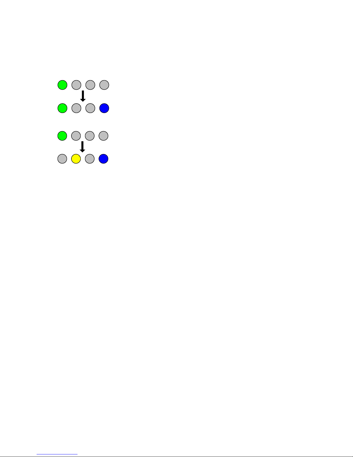
• Transmission of a Safety Relate Message is in icate by both the green an blue LEDs being illuminate
TIMEOUT ERROR STATUSPOWER
• Silent mo e is in icate by both the yellow an blue LEDs being illuminate .
TIMEOUT ERROR STATUSPOWER
Antennas
The TRANSAS AIS CLASS B - unit requires VHF an GPS antennae in epen ent from those in use for other purposes. Please
see Appen ix A for etails of the antennae require .
Maintenance
WARNING
Unauthorise opening of the TRANSAS AIS CLASS B system will invali ate the warranty.
CAUTION
Avoi using chemical solvents to clean the TRANSAS AIS CLASS B as some solvents can amage the case
material.
NOTE
The TRANSAS AIS CLASS B contains no user serviceable parts. Contact your Service Agent for repair if
replacing the fuse fails to make the equipment serviceable.

LD2103 V3.0 Page 16 of 33
SRT Marine
Instruction Manual
SRT-MTB
©
Class B Marine AIS
Serial Data Interface
Power Connection / Data Connection
There is a 15-way D-type male connector mounte un er the transpon er top cover. The stan ar ata or power an ata
cable assembly provi e mates with this connector.
Power
12V DC (9.6-15.6V) is connecte to the transpon er power supply input via the cable assembly LD1873.
Data
A minimum keypa an isplay (MKD) unit, chart plotter or other isplay evice may be connecte to the TRANSAS AIS
CLASS B unit via the appropriate cable assembly. The efault bau rate of the ata link is 38.4kBau with 8 ata bits, one stop
bit an no parity. No han shaking is use .
The ata interface conforms to IEC 61162-1.
VDM, VDO, ACA, ACS, ALR, TXT an ACK messages conform to NMEA 0183. Please refer to NMEA 0183 for full etails of
these AIS messages.
Serial Port Input/Output
There are two serial ports, one presenting RS422 format an the other RS232 format. Data can be input from either or both
ports.
The serial port interface(s) output:
• At power-up boot-loa er an main application splash text screens inclu ing version numbers an memory status.
• As a VHF Data Link Message (VDM) all incoming VHF Data Link (VDL) ata receive by the TRANSAS AIS CLASS B.
• The VHF ata link own vessel (VDO) messages sent by the TRANSAS AIS CLASS B over the VHF Data Link.
• AIS regional channel assignment messages (ACA) receive . These are erive from an incoming VHF Data Link
message (message 22) or a DSC message.
• AIS channel management information source (ACS) messages.
• Alarm messages (ALR, TXT).
The ata interface will accept:
• Personality programming messages
• Alarm acknowle gement messages (ACK)

LD2103 V3.0 Page 17 of 33
SRT Marine
Instruction Manual
SRT-MTB
©
Class B Marine AIS
Power up messages
On power up the unit will report etails of the firmware versions resi ing in the unit.
VHF ata link messages (NMEA 0183 VDM)
Receipt of a VHF Data Link (VDL) message on either AIS ra io channel causes a VDM message to be output via the ata port.
Please see IEC 61193-2, Annex B for a list of messages.
VDM Message Format
!--VDM,x1,x2,x3,a,s--s,x*hh<CR><LF>
Where:
• x1 = Total number of sentences nee e to transfer the message , 1 to 9
• x2 = Sentence number, 1 to 9
• x3 = Sequential message i entifier, 0 to 9
• a = AIS Channel, "A" or "B"
• s - - s = Encapsulate ITU-R M.1371 ra io message
• x = Number of fill-bits , 0 to 5
VDM Message Types
For example, the information containe in the s - - s portion of the VDM = Encapsulate ITU-R M.1371 ra io message. Note
that messages 5 an 19 may be sent as multi part messages using the x1, x2 an x3 parameters for message sequence
control.
VDL Message number VDM Message description
AIS Target Display Information
1, 2, 3, 9,18, 21 position report
4 base station report
5* voyage relate ata
19* Class B – exten e ata
Safety message handling
12 a resse safety relate
14 broa cast safety relate
External Application handling
6 binary a resse
8 binary broa cast
System control
7 binary acknowle ge (INFO)
10 UTC an ata inquiry (INFO)
11 UTC an ata response (INFO)
13 safety relate ack (INFO)
15 interrogation (INFO)
16 assignment mo e comman (INFO)

LD2103 V3.0 Page 18 of 33
SRT Marine
Instruction Manual
SRT-MTB
©
Class B Marine AIS
VDL Message number VDM Message description
17 DGNSS corrections (INFO)
20 ata link management (INFO)
22 channel management (INFO)
*Note that messages 5 an 19 may be sent as multi part messages.
VHF ata link own vessel messages (NMEA 0183 VDO)
This message escribes the own vessel message being sent.
VDO Message Format
!--VDO,x1,x2,x3,a,s--s,x*hh<CR><LF>
Where
• x1 = Total number of sentences nee e to transfer the message , 1 to 9
• x2 = Sentence number, 1 to 9
• x3 = Sequential message i entifier, 0 to 9
• a = AIS Channel, "A" or "B"
• s - - s = Encapsulate ITU-R M.1371 ra io message 4
• x = Number of fill-bits , 0 to 5
VDO Message number VDO Message description
AIS Target Display Information
13 Safety Relate Acknowle gement
18 Stan ar Class B position report (Inclu es MMSI, SOG, position accuracy, lat, long,
COG, true hea ing,)
24a Class B “CS” Static ata Part A (Inclu es MMSI an vessel name)
24b Class B “CS” Static ata Part B (MMSI, ship type, cargo type, call sign, ship imensions)
Regional Assignment Channel Assignment Message (NMEA 0183 ACA)
An TRANSAS AIS CLASS B unit can receive regional channel management information in two ways: ITU-R M.1371 message
22 or a DSC telecomman receive on channel 70,
ACA Message Format
$--ACA,x,llll.ll,a,yyyyy.yy,a,llll.ll,a1,y1y1y1y1y.y1y1,a2,x1,x2x2x2x2,x3,x4x4x4x4,x5,x6,x7,a3,x8,hhmmss.ss*hh
<CR><LF>
Where
• x = Sequence Number , 0 to 9
• IIII, II, a = Region Northeast corner latitu e – N/S
• yyyyy.yy,a1 = Region Northeast corner longitu e – E/W
• llll.ll,a = Region Southwest corner latitu e – N/S
• y1y1y1y1y1.y1y1,a2 = Region Southwest corner longitu e – E/W
• x1 = Transition Zone Size
• x2x2x2x2 = Channel A

LD2103 V3.0 Page 19 of 33
SRT Marine
Instruction Manual
SRT-MTB
©
Class B Marine AIS
• x3 = Channel A ban wi th
• x4x4x4x4 = Channel B
• x5 = Channel B ban wi th
• x6 = Tx/Rx mo e control
• x7 = Power level control
• a3 = Information source
• x8 = In-Use Flag
• hhmmss.ss = Time of "in-use" change
Channel management information source messages (NMEA 0183 ACS)
This sentence is use in conjunction with the ACA sentence an i entifies the originator of an ACA message.
ACS Message Format
$--ACS,x,xxxxxxxxx, hhmmss.ss,xx,xx,xxxx*hh <CR><LF>
• x = Sequence Number , 0 to 9
• xxxxxxxxx =MMSI of originator
• hhmmss.ss = UTC of receipt of channel management information
• xx = UTC Day, 01 -31
• xx = UTC Month, 01 -12
• xxxx = UTC Year
AIS Alarm Messages (NMEA 0183 ALR, Text)
ALR message format
$--ALR,hhmmss.ss,xxx,A,A,c--c*hh<CR><LF>
Where
• hhmmss.ss = Time of alarm (UTC)
• xxx = Unique alarm number
• A = Alarm con ition
• A = Alarm acknowle ge state
• c--c = alarm escription, text
Alarms escriptions presente are:
• AIS: TX malfunction
• AIS: Antenna VSWR excee s limit
• AIS: Rx channel 1 malfunction
• AIS: Rx channel 2 malfunction
• AIS: general failure
• AIS: no sensor position in use
• AIS: no vali SOG information
• AIS: no vali COG information

LD2103 V3.0 Page 20 of 33
SRT Marine
Instruction Manual
SRT-MTB
©
Class B Marine AIS
• AIS: 12V alarm
• AIS: 5V alarm
• AIS: Loss of serial interface integrity
• AIS: Backgroun noise above -77 Bm
ACK messages
Can be generate by a minimum keypa an isplay (MKD) unit, chart plotter or other isplay evice connecte to the
TRANSAS AIS CLASS B to acknowle ge an alarm con ition reporte by the TRANSAS AIS CLASS B.
ACK message format
$--ACK,xxx*hh <CR><LF>
Where
• xxx = unique alarm number
Table of contents


