Trantec S5-ADU User manual

S5-ADU
TRANTEC
ANTENNA DISTRIBUTOR
Thank you for purchasing TRANTEC Antenna Distributor.
Please carefully follow the instructions in this manual to ensure long, trouble-free use of your equipment.
INSTRUCTION MANUAL
1. SAFETY PRECAUTIONS ................................................................................................................. 2
2. GENERAL DESCRIPTION ............................................................................................................... 4
3. HANDLING PRECAUTIONS ............................................................................................................ 4
4. NOMENCLATURE AND FUNCTIONS ............................................................................................. 4
Front .................................................................................................................................................. 4
Rear ................................................................................................................................................... 4
5. CONNECTION .................................................................................................................................. 5
6. OPERATION ..................................................................................................................................... 6
7. RACK MOUNTING ............................................................................................................................ 6
7.1. When mounting two S5-ADU units in a 19" Rack ....................................................................... 6
7.2. When mounting one S5-ADU unit with front mount antenna inputs in a 19" Rack ..................... 7
8. SPECIFICATIONS ............................................................................................................................ 8
Accessories ....................................................................................................................................... 8
TABLE OF CONTENTS

2
Indicates a potentially hazardous situation which,
if mishandled, could result in moderate or minor
personal injury, and/or property damage.
CAUTION
1. SAFETY PRECAUTIONS
• Beforeinstallationoruse,besuretocarefullyread
all the instructions in this section for correct and
safe operation.
• Besuretofollowalltheprecautionaryinstructions
in this section, which contain important warnings
and/or cautions regarding safety.
• After reading, keep this manual handy for future
reference.
Safety Symbol and Message Conventions
Safety symbols and messages described below are used
in this manual to prevent bodily injury and property damage
whichcouldresultfrommishandling.Beforeoperatingyour
product,readthismanualrstandunderstandthesafety
symbols and messages so you are thoroughly aware of the
potential safety hazards.
When Installing the Unit
• Do not expose the unit to rain or an environment
where it may be splashed by water or other liquids,
asdoingsomayresultinreorelectricshock.
• Use the unit only with the voltage specied on
the unit. Using a voltage higher than that which is
speciedmayresultinreorelectricshock.
• Do not cut, kink, otherwise damage nor modify
the power supply cord. In addition, avoid using the
powercordincloseproximitytoheaters,andnever
place heavy objects -- including the unit itself -- on
the power cord, as doing so may result in re or
electric shock.
• Avoid installing or mounting the unit in unstable
locations, such as on a rickety table or a slanted
surface. Doing so may result in the unit falling
down and causing personal injury and/or property
damage.
• Topreventlightningstrikes,installtheunitatleast
vemetersawayfromalightningrod,andyetwithin
the protective range (angle of 45°) of the lightning
conductor. Lightning strikes may cause a re,
electric shock or personal injury.
• Since the unit is designed for indoor use, do not
install it outdoors. If installed outdoors, the aging of
parts causes the unit to fall off, resulting in personal
injury. Also, when it gets wet with rain, there is a
danger of electric shock.
When the Unit is in Use
• Should the following irregularity be found during
use, immediately switch off the power, disconnect
the power supply plug from the AC outlet and
contact your nearest TOA dealer. Make no further
attempt to operate the unit in this condition as this
maycausereorelectricshock.
· If you detect smoke or a strange smell coming
from the unit.
· If water or any metallic object gets into the unit
· If the unit falls, or the unit case breaks
· Ifthepowersupplycordisdamaged(exposureof
the core, disconnection, etc.)
· If it is malfunctioning (no tone sounds.)
• Topreventareorelectricshock,neveropennor
remove the unit case as there are high voltage
components inside the unit. Refer all servicing to
qualiedservicepersonnel.
• Do not place cups, bowls, or other containers of
liquid or metallic objects on top of the unit. If they
accidentallyspillintotheunit,thismaycauseare
or electric shock.
• Do not touch the plugs or antenna cables during
thunder and lightning, as this may result in electric
shock.
• To prevent the electromagnetic wave from badly
inuencingmedicalequipment,makesuretoswitch
offtheunit’spowerwhenplacingitincloseproximity
to the medical equipment.
When Installing the Unit
• Never plug in nor remove the power supply plug
with wet hands, as doing so may cause electric
shock.
• Whenunpluggingthepowersupplycord,besureto
grasp the power supply plug; never pull on the cord
itself. Operating the unit with a damaged power
supplycordmaycauseareorelectricshock.
• Whenmovingtheunit,besuretoremoveitspower
supply cord from the wall outlet. Moving the unit
with the power cord connected to the outlet may
causedamagetothepowercord,resultinginreor
electric shock. When removing the power cord, be
sure to hold its plug to pull.
• The socket outlet shall be installed near the
equipment and shall be easily accessible.
Indicates a potentially hazardous situation which,
if mishandled, could result in death or serious
personal injury.
WARNING

3
• Avoidinstallingtheunitinhumidordustylocations,
inlocationsexposedtothedirectsunlight,nearthe
heaters, or in locations generating sooty smoke
or steam as doing otherwise may result in re or
electric shock.
• Avoid touching the unit’s sharp metal edge to
prevent injury.
• Toavoidelectricshocks,besuretoswitchoffthe
unit’s power when connecting antennas.
• Besuretofollowtheinstructionsbelowwhenrack-
mountingtheunit.Failuretodosomaycauseare
or personal injury.
· Installtheequipmentrackonastable,hardoor.
Fixitwithanchorboltsortakeotherarrangements
to prevent it from falling down.
· When connecting the unit’s power cord to an AC
outlet, use the AC outlet with current capacity
allowable to the unit.
When the Unit is in Use
• Donotplaceheavyobjectsontheunitasthismay
cause it to fall or break which may result in personal
injury and/or property damage. In addition, the
object itself may fall off and cause injury and/or
damage.
• UsethededicatedACadapterfortheunit.Notethat
theuseofotheradaptermaycauseare.
• If dust accumulates on the power supply plug or
in the wall AC outlet, a re may result. Clean it
periodically. In addition, insert the plug in the wall
outlet securely.
• Switchoffthepower,andunplugthepowersupply
plug from the AC outlet for safety purposes when
cleaning or leaving the unit unused for 10 days or
more.Doingotherwisemaycauseareorelectric
shock.
FCC Compliance
This device complies with Part 15 of the FCC Rules.
Operation is subject to the following two conditions:
(1) this device may not cause harmful interference,
and
(2) this device must accept any interference
received, including interference that may cause
undesired operation.
Any modications made to this device that are not
approved by TOA Corporation may void the authority
granted the user by the FCC to operate this equipment.
Note: This equipment has been tested and found to
comply with the limits for a Class B digital device,
pursuant to Part 15 of the FCC Rules. These limits are
designed to provide reasonable protection against
harmful interference in a residential installation. This
equipment generates, uses and can radiate radio
frequency energy and, if not installed and used in
accordance with the instructions, may cause harmful
interference with radio communications. However,
there is no guarantee that interference will not occur in
a particular installation. If this equipment does cause
harmful interference to radio or television reception,
which can be determined by turning the equipment
off and on, the user is encouraged to try to correct
the interference by one or more of the following
measures:
• Reorient or relocate the receiving antenna.
• Increase the separation between the equipment and the
receiver.
• Connect the equipment into an outlet on a circuit different
from that to which the receiver is connected.
• Consult the dealer or an experienced radio/television
technician for help.

4
2. GENERAL DESCRIPTION
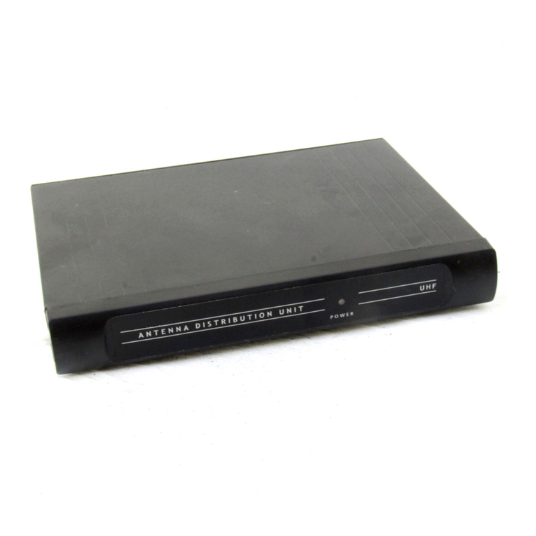
The TRANTEC Wireless Antenna Distributor S5-ADU is designed to be used in conjunction with a UHF band
system for sound reinforcement applications.
It comes with 2 channels, in which a single antenna signal is distributed to 5 outputs.
3. HANDLING PRECAUTIONS
• Wheninstalling,keeptheunit,receivingantennas,andantennacablesasfarawayaspossiblefromuorescent
lamps, digital equipment, personal computers, and other equipment which generate RF frequency noise.
• Donotinstallthereceivingantennasincloseproximitytometalobjects,suchasironframesandlockers.
Keep the antennas at least 30 cm (11.81") away from the wall surface.
• Pairsofantennasshouldbeatleast3m(9.84ft)awayfromeachothertoobtaintheoptimumdiversityeffect,
although this distance differs depending on the construction and size of the room where they are installed.
• Whencleaningthecase,useadrycloth.Neverusebenzine,thinnerorothervolatileliquids.
4. NOMENCLATURE AND FUNCTIONS
[Front]
2
1
1. Power switch
Press this switch to switch on the power. Press this
switch again to switch off the power.
2. Power lamp
Lights when the power is switched on.
[Rear]
4
56 6
3
77
4
3. DC power input
Connect the power cable of AC adapter* to this
jack.
* "A" version : Supplied
"W" version : Consult your TOA dealer.
4. Antenna link output A, B
50 Ω, BNC. Connect the additional S5-ADU
antenna input.

5
5. Cable hanger
Hook the power cable onto this part.
6. Antenna distribution output A, B
50Ω,BNC.
7. Antenna input A, B
50Ω,BNC.Delivers9VDC/25mAforsupplying
powertoanexternalantenna.
Cable hanger
Power cable
5. CONNECTION
• Upto4tunerscanbeconnectedtotheantennadistributionoutputsofS5-ADUusing1or2receivingantennas.
• OneS5-ADUoronetunercanbeconnectedtotheantennalinkoutputsoftheS5-ADU.
• ThelengthoftheantennacablesbetweentheS5-ADUandthedependentequipment(ex.tunerorS5-ADU)
mustnotexceed1m(3.28ft).
• Antennasandboostersareforindooruseonly.
Antenna A
Connect to the antenna input
of another S5-ADU
Antenna B
S5-ADU
S5 Tuner
S5 Tuner
S5 Tuner
S5 Tuner

6
6. OPERATION
Step 1. Turn on the power of both the S5-ADU and connected tuners (the power lamp lights)
Step 2. Set the wireless microphone switch to the ON position.
7. RACK MOUNTING
The rack mounting kit is available as an accessory for S5 systems.
7.1. When mounting two S5-ADU units in a 19" Rack
Step 1. Remove3caseholdingscrews(M3x6)from
opposite sides of each unit’s case. Then,
mount the rack mounting brackets there using
the screws as shown at right.
Step 2. Remove plastic plugs from top of the units,
insert the joint bar into the case side slots, and
xitwithscrews(M3x6,black).
Step 3. Fix2unitstogetherusingtheremaining2joint
barsandCSKscrews(M3x6)ontheirbottom
side.

7
3
2
Step 1. Remove 3 case holding screws (M3 x
6) from the left hand side (viewed from
front) of the unit’s case, then mount the
rack mounting bracket using the screws
as shown at right.
Step 3. Fitextensioncablesintothefrontpaneloflongmountingbracketasshownbelow,thentightenthe
BNCconnectorswithnuts.Putplasticblankplug(s)inunusedantennainputconnector(s).
7.2. When mounting one S5-ADU unit with front mount antenna inputs in a 19" Rack
Step 2. Remove3caseholdingscrews(M3x6)fromtherighthandsideoftheunit’scase(viewedfromfront),
and mount the long mounting bracket (having 2 antenna inputs) using the screws.

Traceability Information for Europe (EMC directive 2004/108/EC)
Manufacturer:
TOA Corporation
7-2-1, Minatojima-Nakamachi, Chuo-ku, Kobe, Hyogo, Japan
Authorized representative:
TOA Electronics Europe GmbH
Suederstrasse 282, 20537 Hamburg,Germany
133-07-307-2A
8. SPECIFICATIONS
Power Source AC mains, 50/60 Hz (supplied from the included AC adapter)
Current Consumption 300mA(12VDC)
Frequency Range UHF*1
Distribution Channel 2 channels
Antenna Input 1input,50Ω,BNC(phantompoweringof9VDC/25mAforantenna)
Antenna Output 4outputsand1linkoutput,50Ω,BNC
Indicator Power lamp
Operating Temperature –10 to +50°C
Finish Front panel: Aluminum, silver, anodized
Case: Steel plate, dark gray, painting
Dimensions 210(w)x46.4(h)x201.2(d)mm(8.27"x1.83"x7.92")
Weight 1.3 kg (2.87 lb)
Note: Thedesignandspecicationsaresubjecttochangewithoutnoticeforimprovement.
• Accessories
AC adapter*2................................................... 1
BNCcable(forconnection)50cm(1.64ft) ... 10
*1
Band Frequency Range
G606 – 638 MHz, UHF
B722 – 752 MHz, UHF
*2
Version AC Adapter
A240VAC,50Hz
WNot supplied
Anymodicationtotheunit,unlessexpresslyapprovedbyTOAElectronics,Inc.couldvoidtheuser's
authority to operate the equipment.
DECLARATION OF CONFORMITY
TOA Electronics, Inc.
1350BayshoreHighway,Suite270Burlingame,
California 94010, USA
TEL 650-452-1200
declare under our sole responsibility that the product
ANTENNADISTRIBUTORS5-ADU
complies with Part 15 of FCC Rules.
Operation is subject to the following conditions: (1) this device may not cause harmful interference, and
(2) this device must accept any interference received, including interference that may cause undesired
operation.
Table of contents
Other Trantec Antenna manuals

