Endress+Hauser Promag User manual


EA01238D
Endress+Hauser 3
Kit wireless antenna for extended range
Promag, Promass 300, 500, 500 – digital
Table of contents
1 Overview of accessory ............................................................. 4
2 Authorized installation personnel .................................................. 4
3 Safety instructions ................................................................ 4
4 Symbols used ..................................................................... 5
5 Tools list .......................................................................... 6
6 Promag, Promass 300, 500 ........................................................ 6
7 Promag, Promass 500 – digital .................................................... 9

EA01238D
4 Endress+Hauser
1 Overview of accessory
The Installation Instructions apply to the following accessories:
Order code Original accessory Contents
71351317 1 × wireless antenna set 1 × antenna, 1 × antenna feedthrough,
1 × antenna cable, internal 1 × antenna cable
external, 1 × angle bracket
2 Authorized installation personnel
Authorization to carry out installation depends on the measuring device's approval type. The
table below shows the authorized group of people in each case.
Whoever carries out the installation has full responsibility to ensure that work is carried
out safely and to the required quality standard. He/she must also guarantee the safety of
the device following installation.
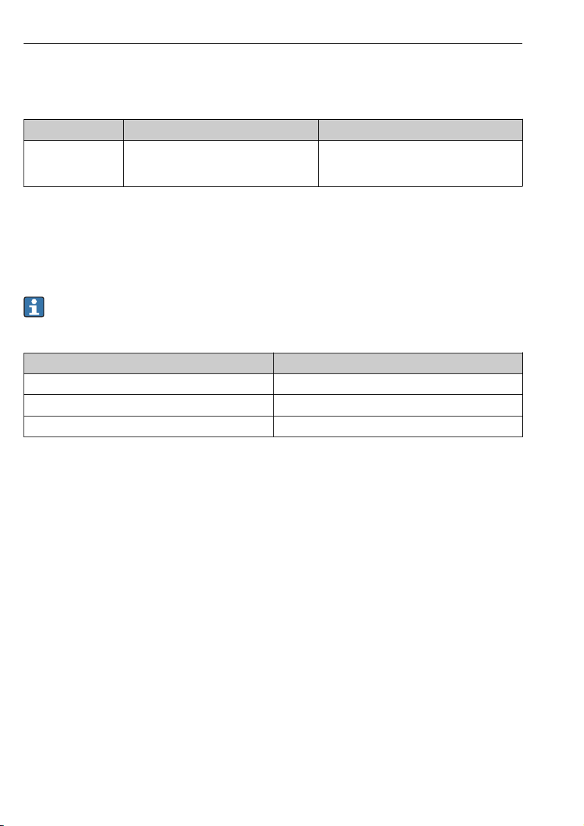
Measuring device approval Authorized installation personnel 1)
Without approval 1, 2, 3
With approval (e.g. IECEx) 1, 2, 3
For custody transfer 4
1) 1 = Qualified specialist on customer side, 2 = Service technician authorized by Endress+Hauser,
3 = Endress+Hauser (return measuring device to manufacturer)
4 = Check with local approval center if installation/modification must be performed under supervision.
3 Safety instructions
• Only use original parts from Endress+Hauser.
• Comply with national regulations governing mounting, electrical installation,
commissioning, maintenance and repair procedures.
• The following requirements must be met with regard to specialized technical staff for the
mounting, electrical installation, commissioning, maintenance and repair of the measuring
devices:
– Specialized technical staff must be trained in instrument safety.
– They must be familiar with the individual operating conditions of the devices.
– In the case of Ex-certified measuring devices, they must also be trained in explosion
protection.
• The measuring device is energized! Risk of fatal injury from electric shock. Open the
measuring device only when the device is deenergized.
• When using Ex-certified measuring devices: open device only when in a deenergized state
(allow 10 minutes to elapse after switching off the power supply) or in environments which
do not have a potentially explosive atmosphere.

EA01238D
Endress+Hauser 5
• When using measuring devices in safety-related applications in accordance with IEC 61508
or IEC 61511: following installation, re-commission the device in accordance with the
Operating Instructions. Document the installation.
• Before removing the device: set the process to a safe state and purge the pipe of dangerous
process substances.
• Hot surfaces! Risk of injury! Before commencing work: allow the system and measuring
device to cool down to a touchable temperature.
• In the case of devices in custody transfer, the custody transfer status no longer applies once
the seal has been removed.
• The Operating Instructions for the device must be followed.
• Risk of damaging the electronic components! Ensure you have a working environment
protected from electrostatic discharge.
• After removal of the electronics compartment cover: risk of electrical shock due to missing
touch protection!
Turn instrument off before removing internal covers.
• Modifications to the measuring device are not permitted.
• Only open housing for a brief period. Avoid the penetration of foreign bodies, moisture or
contaminants.
• Replace defective seals only with original seals from Endress+Hauser.
• If threads are damaged or defective, the measuring device must be repaired.
• Threads (e.g. of the electronics compartment cover and connection compartment cover)
must be lubricated if an abrasion-proof dry lubricant is not available. Use acid-free, non-
hardening lubricant.
• If, during installation, spacing is reduced or the dielectric strength of the measuring device
cannot be guaranteed, perform a test on completion of the work (e.g. high-voltage test in
accordance with the manufacturer's instructions).
• Service plug:
– Do not connect in explosive atmospheres.
– Only connect to Endress+Hauser service devices.
• Observe the instructions for transporting and returning the device outlined in the Operating
Instructions.
If you have any questions, please contact your Endress+Hauser service organization.
4 Symbols used
4.1 Symbols for certain types of information
Symbol Meaning
Permitted
Procedures, processes or actions that are permitted.
Forbidden
Procedures, processes or actions that are forbidden.

EA01238D
6 Endress+Hauser
Symbol Meaning
Tip
Indicates additional information.
1.
,
2.
,
3.
… Series of steps
5 Tools list
3 mm 30 mm 0.5 × 3.5 mm T20
6 Promag, Promass 300, 500
6.1 Mounting the antenna feedthrough
1 → 2 →
3.
Nicht unter
Spannung öffnen
Do not open when
energized
Ne pas ouvrir
sous tension
Power
I/O
N
i
c
ht
u
n
t
e
r
a
r
e
ö
f
f
n
e
n
2.
1. 3 mm
D
i
s
p
l
a
y
+E
ESC
–
Nicht unter
Spannung öffnen
Do not open when
energized
Ne pas ouvrir
sous tension
Power
I/O
+E
ESC
–
1.
1.
2.
3.
N
i
c
ht
u
n
t
e
r
a
r
e
ö
f
f
n
e
n
3 → 4 →
D
i
s
p
l
a
y

EA01238D
Endress+Hauser 7
5 → 6 →
30 mm
4 Nm
1.
2.
3.
7 →
8 → 9 →
+E
ESC
–
Nicht unter
Spannung öffnen
Do not open when
energized
Ne pas ouvrir
sous tension
Power
I/O
+E
ESC
–
2.
3.
2. 1.
N
i
c
ht
u
n
t
e
r
a
r
e
ö
f
f
n
e
n
D
i
s
p
l
a
y
+E
ESC
–
Nicht unter
Spannung öffnen
Do not open when
energized
Ne pas ouvrir
sous tension
Power
I/O
N
i
c
ht
u
n
t
e
r
a
r
e
ö
f
f
n
e
n
3 mm
1.
2.5 Nm (1.8 lbf ft)
2.
3.

EA01238D
8 Endress+Hauser
10
6.2 Mounting the wireless antenna with cable
3.
1.
2.
5.
4.
For detailed information on the electrical connection, see the "Electrical connection"
section of the Operating Instructions for the device.
For detailed information on commissioning, see the "Commissioning" section of the
Operating Instructions for the device.

EA01238D
Endress+Hauser 9
7 Promag, Promass 500 – digital
7.1 Mounting the antenna feedthrough
1 → 2 →
T20
1.
2.
-+-
ESC
2.
1.
3 →
2.
-+-
ESC
1.
4 → 5 →
30 mm
4 Nm

EA01238D
10 Endress+Hauser
6 →
7 → 8 →
2.
-+-
ESC
1.
2.
T20
1.
2.
9

EA01238D
Endress+Hauser 11
7.2 Mounting the wireless antenna with cable
3.
1.
2.
5.
4.
For detailed information on the electrical connection, see the "Electrical connection"
section of the Operating Instructions for the device.
For detailed information on commissioning, see the "Commissioning" section of the
Operating Instructions for the device.


EA01238D
Endress+Hauser 13
Set Wireless Antenne für Weitbereich
Promag, Promass 300, 500, 500-digital
Inhaltsverzeichnis
1 Übersicht Zubehörteil ............................................................ 14
2 Einbauberechtigte Personen ...................................................... 14
3 Sicherheitshinweise .............................................................. 14
4 Verwendete Symbole ............................................................. 15
5 Werkzeugliste ................................................................... 16
6 Promag, Promass 300, 500 ....................................................... 16
7 Promag, Promass 500-digital ..................................................... 19

EA01238D
14 Endress+Hauser
1 Übersicht Zubehörteil
Die Einbauanleitung ist für folgende Zubehörteile gültig:
Bestellnummer Original Zubehörteil Inhalt
71351317 1 × Set Wireless Antenne 1 × Antenne, 1 × Antennendurchführung,
1 × Antennenkabel intern, 1 × Antennenkabel
extern, 1 × Befestigungswinkel
2 Einbauberechtigte Personen
Die Berechtigung zur Durchführung eines Einbaus ist von der Zulassung des Messgeräts
abhängig. Die Tabelle zeigt den jeweils berechtigten Personenkreis.
Die Person, die einen Einbau vornimmt, übernimmt die Verantwortung für die Sicherheit
während der Arbeiten, die Qualität der Ausführung und die Sicherheit des Geräts nach
dem Einbau.
Zulassung des Messgeräts Einbauberechtigter Personenkreis 1)
Ohne Zulassung 1, 2, 3
Mit Zulassung (z.B. IECEx) 1, 2, 3
Bei eichfähigem Verkehr 4
1) 1 = Ausgebildete Fachkraft des Kunden, 2 = Von Endress+Hauser autorisierter Servicetechniker,
3 = Endress+Hauser (Messgerät an Hersteller zurücksenden)
4 = Mit der lokalen Zulassungsstelle prüfen, ob ein Ein-/Umbau unter Aufsicht erfolgen muss.
3 Sicherheitshinweise
• Nur Originalteile von Endress+Hauser verwenden.
• Nationale Vorschriften bezüglich der Montage, elektrischen Installation, Inbetriebnahme,
Wartung und Reparatur einhalten.
• Folgende Anforderungen an das Fachpersonal für Montage, elektrische Installation,
Inbetriebnahme, Wartung und Reparatur der Messgeräte müssen erfüllt sein:
– In Gerätesicherheit ausgebildet.
– Mit den jeweiligen Einsatzbedingungen der Geräte vertraut.
– Bei Ex-zertifizierten Messgeräten: zusätzlich im Explosionsschutz ausgebildet.
• Messgerät unter Spannung! Lebensgefahr durch Stromschlag. Messgerät nur im
spannungslosen Zustand öffnen.
• Bei Ex-zertifizierten Messgeräten: Nur in spannungslosem Zustand (nach Berücksichtigung
einer Wartezeit von 10 Minuten nach Abschalten der Energiezufuhr) oder in Umgebungen
öffnen, die keine explosionsfähige Atmosphäre enthalten.

EA01238D
Endress+Hauser 15
• Bei Messgeräten in sicherheitstechnischen Applikationen gemäß IEC 61508 bzw.
IEC 61511: Nach Einbau Neuinbetriebnahme gemäß Betriebsanleitung durchführen. Einbau
dokumentieren.
• Vor einem Geräteausbau: Prozess in sicheren Zustand bringen und Leitung von gefährlichen
Prozessstoffen befreien.
• Verbrennungsgefahr durch heiße Oberflächen! Vor Arbeitsbeginn: Anlage und Messgerät
auf berührungssichere Temperatur abkühlen.
• Bei Messgeräten im abrechnungspflichtigen Verkehr: Nach Entfernen der Plombe ist der
geeichte Zustand aufgehoben.
• Die Betriebsanleitung zum Messgerät ist zu beachten.
• Beschädigungsgefahr elektronischer Bauteile! Eine ESD-geschützte Arbeitsumgebung
herstellen.
• Nach Entfernen der Elektronikabdeckung: Stromschlaggefahr durch aufgehobenen
Berührungsschutz!
Messgerät ausschalten, bevor interne Abdeckungen entfernt werden.
• Änderungen am Messgerät sind nicht zulässig.
• Gehäuse nur kurzzeitig öffnen. Eindringen von Fremdkörpern, Feuchtigkeit oder
Verunreinigung vermeiden.
• Defekte Dichtungen nur durch Original-Dichtungen von Endress+Hauser ersetzen.
• Defekte Gewinde erfordern eine Instandsetzung des Messgeräts.
• Gewinde (z.B. von Elektronikraum- und Anschlussraumdeckel) müssen geschmiert sein,
sofern keine abriebfeste Trockenschmierung vorhanden ist. Säurefreies, nicht härtendes
Fett verwenden.
• Wenn bei den Einbauarbeiten Abstände reduziert oder die Spannungsfestigkeit des
Messgeräts nicht sichergestellt werden kann: Prüfung nach Abschluss der Arbeiten
durchführen (z.B. Hochspannungstest gemäß Herstellerangaben).
• Servicestecker:
– Nicht in explosionsfähiger Atmosphäre anschließen.
– Nur an Servicegeräte von Endress+Hauser anschließen.
• Die in der Betriebsanleitung aufgeführten Hinweise zum Transport und zur Rücksendung
beachten.
Bei Fragen kontaktieren Sie bitte Ihre zuständige Endress+Hauser Serviceorganisation.
4 Verwendete Symbole
4.1 Symbole für Informationstypen
Symbol Bedeutung
Erlaubt
Abläufe, Prozesse oder Handlungen, die erlaubt sind.
Verboten
Abläufe, Prozesse oder Handlungen, die verboten sind.

EA01238D
16 Endress+Hauser
Symbol Bedeutung
Tipp
Kennzeichnet zusätzliche Informationen.
1.
,
2.
,
3.
… Handlungsschritte
5 Werkzeugliste
3 mm 30 mm 0.5 × 3.5 mm T20
6 Promag, Promass 300, 500
6.1 Antennendurchführung montieren
1 → 2 →
3.
Nicht unter
Spannung öffnen
Do not open when
energized
Ne pas ouvrir
sous tension
Power
I/O
N
i
c
ht
u
n
t
e
r
a
r
e
ö
f
f
n
e
n
2.
1. 3 mm
D
i
s
p
l
a
y
+E
ESC
–
Nicht unter
Spannung öffnen
Do not open when
energized
Ne pas ouvrir
sous tension
Power
I/O
+E
ESC
–
1.
1.
2.
3.
N
i
c
ht
u
n
t
e
r
a
r
e
ö
f
f
n
e
n
3 → 4 →
D
i
s
p
l
a
y

EA01238D
Endress+Hauser 17
5 → 6 →
30 mm
4 Nm
1.
2.
3.
7 →
8 → 9 →
+E
ESC
–
Nicht unter
Spannung öffnen
Do not open when
energized
Ne pas ouvrir
sous tension
Power
I/O
+E
ESC
–
2.
3.
2. 1.
N
i
c
ht
u
n
t
e
r
a
r
e
ö
f
f
n
e
n
D
i
s
p
l
a
y
+E
ESC
–
Nicht unter
Spannung öffnen
Do not open when
energized
Ne pas ouvrir
sous tension
Power
I/O
N
i
c
ht
u
n
t
e
r
a
r
e
ö
f
f
n
e
n
3 mm
1.
2.5 Nm (1.8 lbf ft)
2.
3.

EA01238D
18 Endress+Hauser
10
6.2 Wireless Antenne mit Kabel montieren
3.
1.
2.
5.
4.
Detaillierte Angaben zum elektrischen Anschluss: Kapitel "Elektrischer Anschluss",
Betriebsanleitung zum Gerät.
Detaillierte Angaben zur Inbetriebnahme: Kapitel "Inbetriebnahme", Betriebsanleitung
zum Gerät.

EA01238D
Endress+Hauser 19
7 Promag, Promass 500-digital
7.1 Antennendurchführung montieren
1 → 2 →
T20
1.
2.
-+-
ESC
2.
1.
3 →
2.
-+-
ESC
1.
4 → 5 →
30 mm
4 Nm

EA01238D
20 Endress+Hauser
6 →
7 → 8 →
2.
-+-
ESC
1.
2.
T20
1.
2.
9
Other manuals for Promag
1
This manual suits for next models
3
Table of contents
Languages: