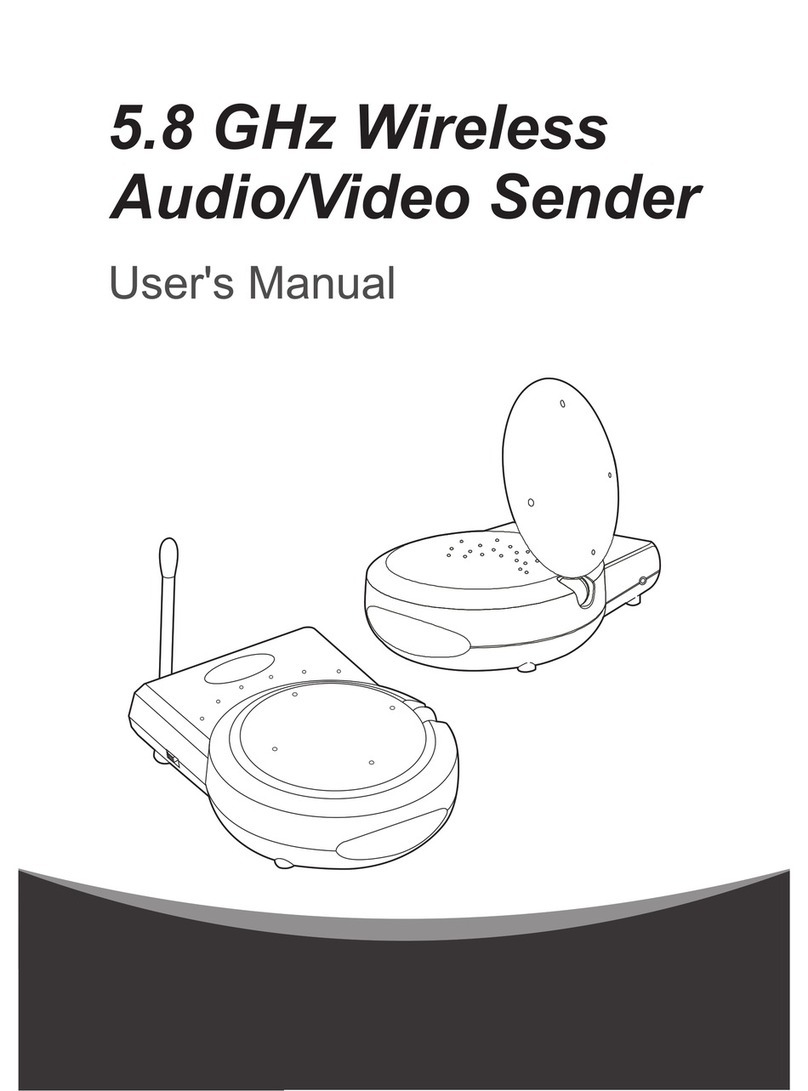
TRANWO Technology TTA-20T User manual

User’s Manual

ContentsContents
ContentsContents
Contents
What You Get ............................................................................................................................................1
Product Layout ..........................................................................................................................................3
Setting Up-Transmitter .............................................................................................................................5
Setting Up-Receiver ..................................................................................................................................9
Setting Up-Remote Control Feature .................................................................................................... 11
Setting Up-Other Applications ............................................................................................................. 13
Orienting Units for Optimal Performance ........................................................................................... 15
Auto-Sequence Function for Multiple Location Monitoring ............................................................ 16
Troubleshooting ...................................................................................................................................... 18
Care and Maintenance ........................................................................................................................... 19
Specifications........................................................................................................................................... 20
Declaration of Conformity .................................................................................................................... 20
FCC Statement ...................................................................................................................................... 20

What YWhat Y
What YWhat Y
What You Getou Get
ou Getou Get
ou Get
The transmitter and receiver look virtually alike. You can find Transmitter and Receiver on the
nameplate of each unit.
•One Transmitter
•One Receiver
•One Infrared (IR) Emitter
•Two Audio/Video Cables (RCA to RCA cables for NTSC or RCA to Scart cables for PAL)
•Two Power Adapters
•Fastener Strip (for fixing the IR Emitter)
•One Quick Installation Guide
•This User's Manual
Transmitter
1
English
Receiver

Product LayoutProduct Layout
Product LayoutProduct Layout
Product Layout
Front View of Transmitter/ReceiverFront View of Transmitter/Receiver
Front View of Transmitter/ReceiverFront View of Transmitter/Receiver
Front View of Transmitter/Receiver
2
2
Front View of
Transmitter
Rear View of
Transmitter
Front View of
Receiver
Rear View of
Receiver
3
4
5678
9
10
5
678
9
11
2

Product LayoutProduct Layout
Product LayoutProduct Layout
Product Layout
3
Power Indicator LED
The LED should be lit when the ON/OFF switch is in the ON position..
2.4GHz Audio/Video Antenna (Front )
Transmits and receives Audio/Video signals. Caution: Antenna does not rotate freely 360 degrees. (See
"Orienting Units for Optimal Performance", on page 15)
IR Emitter Port
Channel Selection Switch
Select the channel by sliding the slide switch to the channel number you want.
Must select the same channel both on transmitter and receiver.
Left Audio Jack (White)
Right Audio Jack (Red)
Video Jack (Yellow)
9V Power Adapter Plug
ON/OFF Switch
Channel Selection Dipswitches
Select the channel by setting the channel dipswitch to the ON position. The number 5 dipswitch
sets the timer for the auto-sequence function (see "Auto-Sequence Function for Multiple Location
Monitoring", on page 16).
Must select the same channel both on transmitter and receiver.
1
2
3
4
5
6
7
8
9
10

Setting UpSetting Up
Setting UpSetting Up
Setting Up
Before you make the connection:
•Always make sure the unit ON/OFF switch is in the OFF position.
•Set the channel switches on the back of the transmitter and receiver to the same channel.
•Depending on the type of TV you own and the component audio/video system (VCR,
DVD player, satellite receiver, LD player etc.), connection methods will be different. We
recommend you refer to the connected audio/video component's user's manual for details,
then make connections according to the following steps.
Transmitter Receiver
4

Setting Up-Setting Up-
Setting Up-Setting Up-
Setting Up-TransmitterTransmitter
TransmitterTransmitter
Transmitter
Connecting the Transmitter to an Audio/Video ComponentConnecting the Transmitter to an Audio/Video Component
Connecting the Transmitter to an Audio/Video ComponentConnecting the Transmitter to an Audio/Video Component
Connecting the Transmitter to an Audio/Video Component
Connect one set of audio/video cables to the audio/video jacks of the transmitter,
matching the plug colors with the jacks on the transmitter.
1
Connect the other end of the cable to the audio/video jacks on the audio/video component
labeled LINE OUT, matching the plug colors with the jacks on the audio/video component.
Some connection scenarios are shown on the next page.
Note: For PAL systems, the connector on the
audio/video component is a Scart socket.
Connect the Scart connector labeled
TRANSMITTER to the Scart socket labeled
OUT on the audio/video component; connect
the RCA connector to the transmitter.
Transmitter
Audio/Video Component
RCA to Scart Cable
Transmitter
2
5

Setting Up-Setting Up-
Setting Up-Setting Up-
Setting Up-TransmitterTransmitter
TransmitterTransmitter
Transmitter
Connecting to a TV with Audio/Video Out Jacks
Connecting to a TV without Audio/Video Out Jacks
Note:
If the audio/video
component has only one
output for audio (mono
sound only), connect the
white plug to that single
audio output and to the
transmitter's AUDIO
LEFT jack.
If the jacks on the audio/
video component are
colored differently,
connect the yellow plug to
the jack labeled VIDEO,
the red plug to the jack
labeled AUDIO RIGHT,
and the white plug to the
jacklabeledAUDIOLEFT.
Transmitter
Audio/Video
Componet
OUT VIDEO AUDIO VIDEO AUDIO IN
OUT
TV
TV
Transmitter
Audio/Video
Componet
OUT VIDEO AUDIO VHF/UHF
ANT. IN
RF OUT
6

Setting Up-Setting Up-
Setting Up-Setting Up-
Setting Up-TransmitterTransmitter
TransmitterTransmitter
Transmitter
Connecting to Multiple Audio/Video Components
To use the Wireless Audio/Video Sender for
two or more audio/vidoe component, first
identify the last component in the chain and
connect its LINE OUT jacks to the
transmitter.
If the final component of the chain does not
have spare LINE OUT jacks, use coaxial cable
to connect the VHF/UHF jacks on the TV
and the last component. Then connect the
transmitter to the last compontnt's LINE
OUT jacks.
Audio/Video
Componet
Audio/Video
Componet
Audio/Video
Componet
TV
VHF/UHF
Transmitter
RF OUT
VIDEO AUDIO
IN
OUT
VIDEO AUDIO
IN
OUT
VIDEO AUDIO
OUT
Plug one end of the provided power
adapter into a wall outlet and the other
end into the rear of the transmitter.
Turn the ON/OFF switch to the ON positon.
The LED on the front of the unit should light.
Place the transmitter in a convenient
location, then adjust its antenna so that the
front (curved face) faces the room where
the receiver is set up. See "Orienting Units
for Optimal Performance", on page 15).
3
4
5
7

Setting Up-ReceiverSetting Up-Receiver
Setting Up-ReceiverSetting Up-Receiver
Setting Up-Receiver
Connect one set of audio/video cables to the audio/video jacks of the receiver, matching the
plug colors with the jacks on the receiver.
Connect the other end of the cable to the audio/video jacks on the TV labeled LINE IN,
matching the plug colors with the jacks on the TV. Some connection scenarios are shown on
the next page.
11
11
1
2
Connecting the Receiver to a TVConnecting the Receiver to a TV
Connecting the Receiver to a TVConnecting the Receiver to a TV
Connecting the Receiver to a TV
Note: For PAL systems, the connector on
the audio/video component is a Scart socket.
Connect the Scart connector labeled
RECEIVER to the Scart socket labeled IN
on the audio/video component; connect the
RCA connector to the receiver.
Receiver
Audio/Video Component
RCA to Scart Cable
Receiver
8

Setting Up-ReceiverSetting Up-Receiver
Setting Up-ReceiverSetting Up-Receiver
Setting Up-Receiver
Connecting to a TV With an Audio/Video Component
Receiver
Connecting to a TV Without Audio/Video IN Jacks
If your TV has UHF/VHF input only, and there is no audio/video
equipment near your TV, you will need to get an RF-Modulator
(available at your local electronic store) to convert the RCA jacks to
coax. Then select either channel 3 or 4 on your TV to view the video.
Note:
If the TV has only one input
for audio (mono sound
only), connect the white
plug to that single audio
input and to the receiver's
AUDIO LEFT jack.
If the jacks on the TV are
colored differently, connect
the yellow plug to the jack
labeled Video, the red plug
to the jack labeled AUDIO
RIGHT, and the white plug
to the jack labeled AUDIO
LEFT.
VIDEO AUDIO
RF OUT
TV
RF Modulator
CH 3/4 VHF/UHF
TV
VIDEO AUDIO IN
Receiver
9

Plug one end of the provided power adapter into a wall outlet and the other end into the rear of
the receiver.
Turn the ON/OFF switch to the ON position. The LED on the front of the unit should light.
Place the receiver in a convenient location, then adjust its antenna so that the front (curved face)
faces the room where the transmitter is set up. See "Orienting Units for Optimal Performance",
on page 15.
Connecting to a TV With an Audio/Video Component
Setting Up-ReceiverSetting Up-Receiver
Setting Up-ReceiverSetting Up-Receiver
Setting Up-Receiver
3
4
5
Receiver
VIDEO AUDIO RF OUT
TV
Audio/Video
Component
VHF/UHF
10

11
Setting Up-Remote Control FeatureSetting Up-Remote Control Feature
Setting Up-Remote Control FeatureSetting Up-Remote Control Feature
Setting Up-Remote Control Feature
This product gives you the ability to control audio/video components using your existing remote
control device. The infrared (IR) signal emitted by your remote control is converted to a radio frequency
(RF) signal at the receiver. It is then sent to the transmitter, where the RF signal is converted back to
the original IR signal and used to control the audio/video source through the IR extender mouse.
To use the IR extender mouse, follow the steps below.
Plug the IR extender mouse into the jack located on the side of the transmitter.
Point the IR extender mouse to the IR sensor on the audio/vido source component.
Position the receiver so that your remote control signal can strike the IR window on the front of
the unit.
To use your remote control, point it at the front of the receiver and operate it as you normally
would.
1
3
4
2

1
23
4
Setting Up-Remote Control FeatureSetting Up-Remote Control Feature
Setting Up-Remote Control FeatureSetting Up-Remote Control Feature
Setting Up-Remote Control Feature
Audio/Video Source
Component
Transmitter
Receiver
IR Emitter
RemoteControl
TV
12

Setting Up-Other ApplicationsSetting Up-Other Applications
Setting Up-Other ApplicationsSetting Up-Other Applications
Setting Up-Other Applications
Connecting to a CamcorderConnecting to a Camcorder
Connecting to a CamcorderConnecting to a Camcorder
Connecting to a Camcorder
The Wireless Audio/Video Sender can be used to send a picture from camcorders to any TV without
wires.
•Connect one set of audio/video cables to the audio/video jacks of the transmitter and to the output
jacks of the camcorder, matching the plug colors with the jacks on both the transmitter and
camcorder.
•If your camcorder only has a mini-plug audio/video output, you will need a "Y" adapter patch cord
(which comes with the camera) to convert the mini-plug to RCA plugs.
Connecting to a Stereo SystemConnecting to a Stereo System
Connecting to a Stereo SystemConnecting to a Stereo System
Connecting to a Stereo System
You can conntct the Wireless Audio/Video to your stereo system, to enjoy sound from your CD player,
cassette deck, or radio, on speakers in another room.
•Connect one set of audio/video cables to the two audio jacks (red and white) of the transmitter and
to the stereo system, matching the plug colors with the jacks on the transmitter. The yellow video
plug is not used.
•Connect one set of audio/video cables to the two audio jacks (red and white) of the receiver and to
the IN 1 or IN 2 jacks on your stereo receiver or amplifier, matching the plug colors with the jacks
on both the component and transmitter. The yellow video plug is not used.
13

14
Setting Up-Other ApplicationsSetting Up-Other Applications
Setting Up-Other ApplicationsSetting Up-Other Applications
Setting Up-Other Applications
Transmitting from a ComputerTransmitting from a Computer
Transmitting from a ComputerTransmitting from a Computer
Transmitting from a Computer
The Wireless Audio/Video Sender can send computer images and sounds (e.g. high-resolution DVD) to
a large TV screen without running wires between the two. To use this features your computer must be
provided with audio output (sound card or onboard audio) and TV output (VGA card with TV-out,
external VGA-to-TV converter, or onboard TV-out).
•Connect the yellow video plug of the audio/video cable to the video jack on the back of the
computer or external VGA-to-TV converter, and to the video jack of the transmitter.
•Connect the mini stereo plug of the adapter (available in any electronic store) into the AUDIO
OUT jack on back of computer, and the red and white audio/vdieo plugs into the AUDIO LEFT
and AUDIO RIGHT jacks on the transmitter.
Receiving on a ComputerReceiving on a Computer
Receiving on a ComputerReceiving on a Computer
Receiving on a Computer
In conjunction with a video capture or TV tuner device, you can turn your computer into a second TV
without running wires between the computer and your audio/video component.
•Connect the yellow video plug of the audio/video cable to the video jack on the TV tuner device or
video capture card, and to the video jack of the receiver.
•Connect the mini stereo plug of the adapter (available in any electronic store) into the AUDIO IN
jack on the back of computer, and the red and white audio/video plugs into the AUDIO LEFT and
AUDIO RIGHT jacks on the receiver.

Orienting Units for Optimal PerformanceOrienting Units for Optimal Performance
Orienting Units for Optimal PerformanceOrienting Units for Optimal Performance
Orienting Units for Optimal Performance
Placing:Placing:
Placing:Placing:
Placing:
Place the transmitter and receiver on a flat, stable surface to prevent damage from falling.
For optimal performance, try to place the units as high as possible to avoid any possible interference
from people walking between the transmitter and the receiver.
Microwave ovens can cause interference. Be sure you do not position the transmitter and receiver
with a microwave in the path between them.
Adjusting the Audio/Video AntennasAdjusting the Audio/Video Antennas
Adjusting the Audio/Video AntennasAdjusting the Audio/Video Antennas
Adjusting the Audio/Video Antennas
For optimal reception, the antennas on both transmitter and
receiver should be oriented. In most situations the curved face
of the audio/video antennas on both the transmitter and receiver
should be facing each other. If the transmitter and
receiver are less than 10 feet (3 meters) apart, keep the audio/video
antennas flat in their casings.
The audio/video antennas have been designed to pivot but have limited rotation in
either clockwise or counterclockwise directions. Antenna does not rotate freely 360
degrees. Rotating past the point where resistance is felt will result in permanent
damage to both antenna and mechanical stopper.
15

Auto-Sequence Function for Multiple Location MonitoringAuto-Sequence Function for Multiple Location Monitoring
Auto-Sequence Function for Multiple Location MonitoringAuto-Sequence Function for Multiple Location Monitoring
Auto-Sequence Function for Multiple Location Monitoring
The receiver's built in auto-sequence function is ideal for security use. The receiver can be used with up
to four cameras on four different channels and display them in sequence on a single TV/monitor. The
receiver's various operating modes are set via dipswitches as shown in the following diagram:
Dipswitches 1 ~ 4: Set up the automatic channel sequence function
Slide the channel dipswitch that you wish to view to the ON position.
Diswitch 5: Sets the sequence change interval time
ON: Changes channel every eight seconds.
OFF: Changes channel every four seconds.
Factory-Preset Mode
16

Auto-Sequence Function for Multiple Location MonitoringAuto-Sequence Function for Multiple Location Monitoring
Auto-Sequence Function for Multiple Location MonitoringAuto-Sequence Function for Multiple Location Monitoring
Auto-Sequence Function for Multiple Location Monitoring
Note 1: The receiver will auto detect the receiving channels, and display them in sequence. When
only one channel dip switch is in the ON position, the receiver will receive the channel
continuously, without regard to the position of the 5th dip switch. If more than one dip
switch remains on, the auto-sequence function will continue on those channels.
Note 2: When none of the dip switches are in the ON position, the receiver will automatically set the
receiving channel to Channel 1.
Example:
Using the auto-sequence function:
If you have two wireless camera and their channels are set on
CHANNEL 1 and CHANNEL 3, and you wish to monitor the
two channels in sequence, you must slide up the first and third
dip switches to the ON position (see the diagram on the right).
If you wish these two channels to be alternated at eight-second
intervals, slide the DIP 5 switch to the ON position. Leave it in
the lower position for four-second channel change intervals.
17
Stopping the auto-sequence function:
To stop the auto-sequence function and lock on one channel, leave the dip switch for the channel you
want to receive in the ON position. Slide the others to the lower position.

TroubleshootingTroubleshooting
TroubleshootingTroubleshooting
Troubleshooting
If you are not getting any signal at allIf you are not getting any signal at all
If you are not getting any signal at allIf you are not getting any signal at all
If you are not getting any signal at all
•Check that the transmitter and receiver are properly connected to the audio/video components
from which you want to send/receive the audio/video s signal
•Make sure that the transmitter is connected to the surce device and the receiver to the receiving
device
•Check the power ON/OFF switches on the transmitter and receiver
•Check power switches on the remote TV and video source (VCR, laser disc player, satellite receiver,
etc.).
•Make sure power plugs are pushed all the way in.
•Check all cable connections.
•Check the CHANNEL switch on both transmitter and receiver are set to the same number
•If you connect the receiver to a TV through an RF modulator, check that the TV is tuned to the
same channel as the TV Channel switch on the RF modulator (3 or 4)
If the signal is poor, or there is interferenceIf the signal is poor, or there is interference
If the signal is poor, or there is interferenceIf the signal is poor, or there is interference
If the signal is poor, or there is interference
•Adjust the antennas orientation (see "Orienting Units for Optimal Performance", on page 15)
•Change the channel on both transmitter and receiver and make them the same.
•If there is a microwave oven in use in the path between the camera and monitor, remove the
microwave oven or turn it off
•Make sure the transmitter and receiver are within range (up to 300 feet)
•Check the channel dipswitch positions on the receiver
18
This manual suits for next models
1
Table of contents
Languages:
Other TRANWO Technology Receiver manuals
