TRAXX EP5LFB User manual

!
!
!
!
!
!
!
!!!!! !
!
!
!
! ! OPERATIONS!MANUAL!
TRAXX!EP5LFB!&!EP7FB!STONE!GRINDER!
Unit!4/1!Rocklea!Drive!
Port!Melbourne!Vic!3207!
Australia!
1300!109!108!
www.traxxcp.com.au!
2
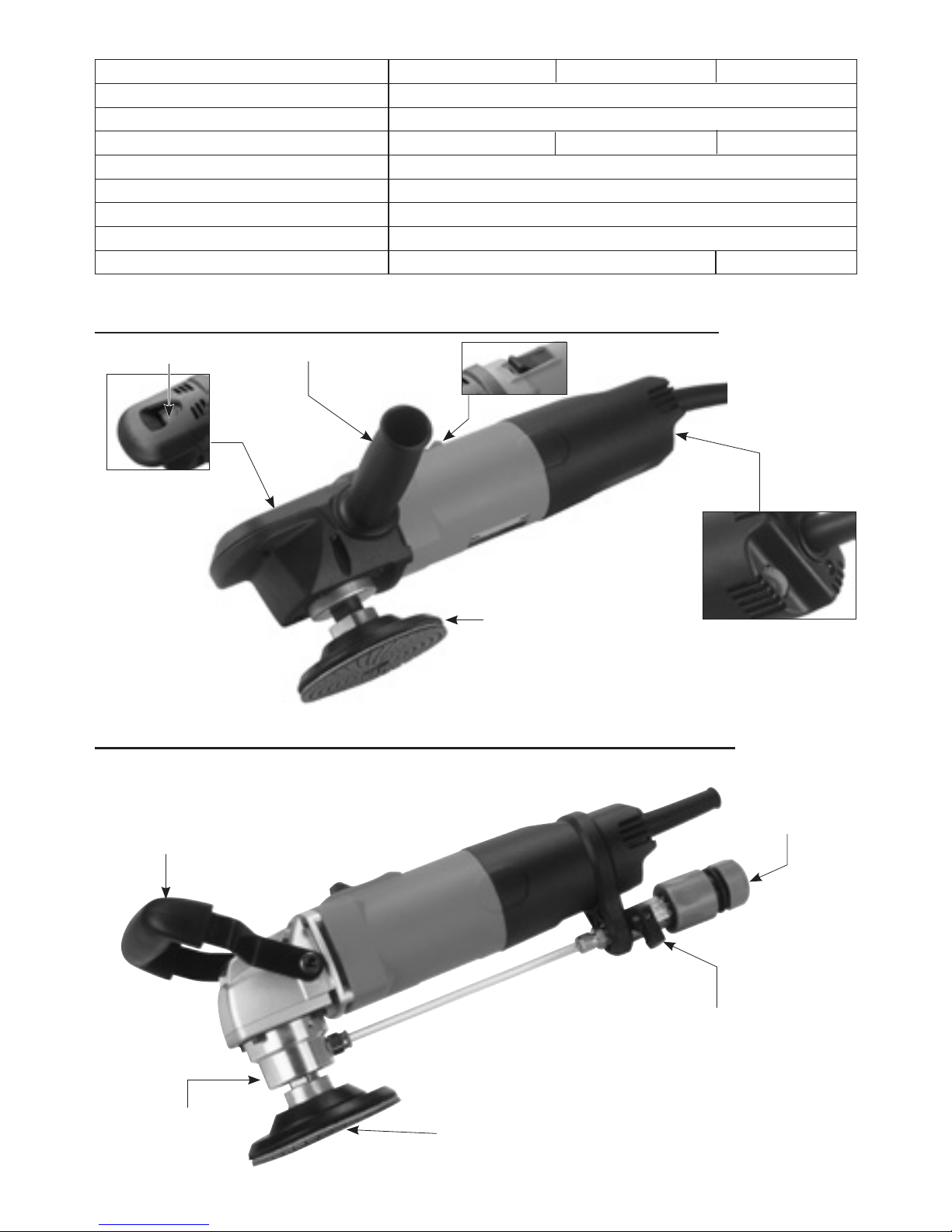
125mm Backing Plate Speed Adjustment
Thumbwheel
Side handle
Spindle Lock On / Off Switch
Water Feed Collar
5" Wet-Dry Mode
5" Dry Mode (High/Low Speed Mode )
Quick-release
water hose
coupling
Quick change conversion
to wet or dry
Uses 125mm hook and loop diamond
polishing pads (not included)
Front Handle
Model 5" High speed mode 5" Low speed mode 5" Wet-Dry mode
Power input 1200W
Voltage See machine nameplate
No Load min-1 3000 ~ 6500 1700 ~ 3700 1700 ~ 3700
Spindle M14
Max. Disc Diameter 5" (125 mm)
Soft Start & Overload Protection With
Dimensions 303mm ( L ) X 72mm ( W ) X 80mm ( H )
Net Weight 2.0 kg (4.4 Lbs) 2.57 kg (5.7 Lbs)
3
Model 5" Dust Collect Cover Mode
Power input 1200W
Voltage See machine nameplate
No Load min-1 1700 ~ 3700
Spindle M14
Max. Disc Diameter 5" (125 mm)
Soft Start & Overload Protection With
Dimensions 303mm ( L ) X 72mm ( W ) X 80mm ( H )
Net Weight 2.8 kg (6.16Lbs)
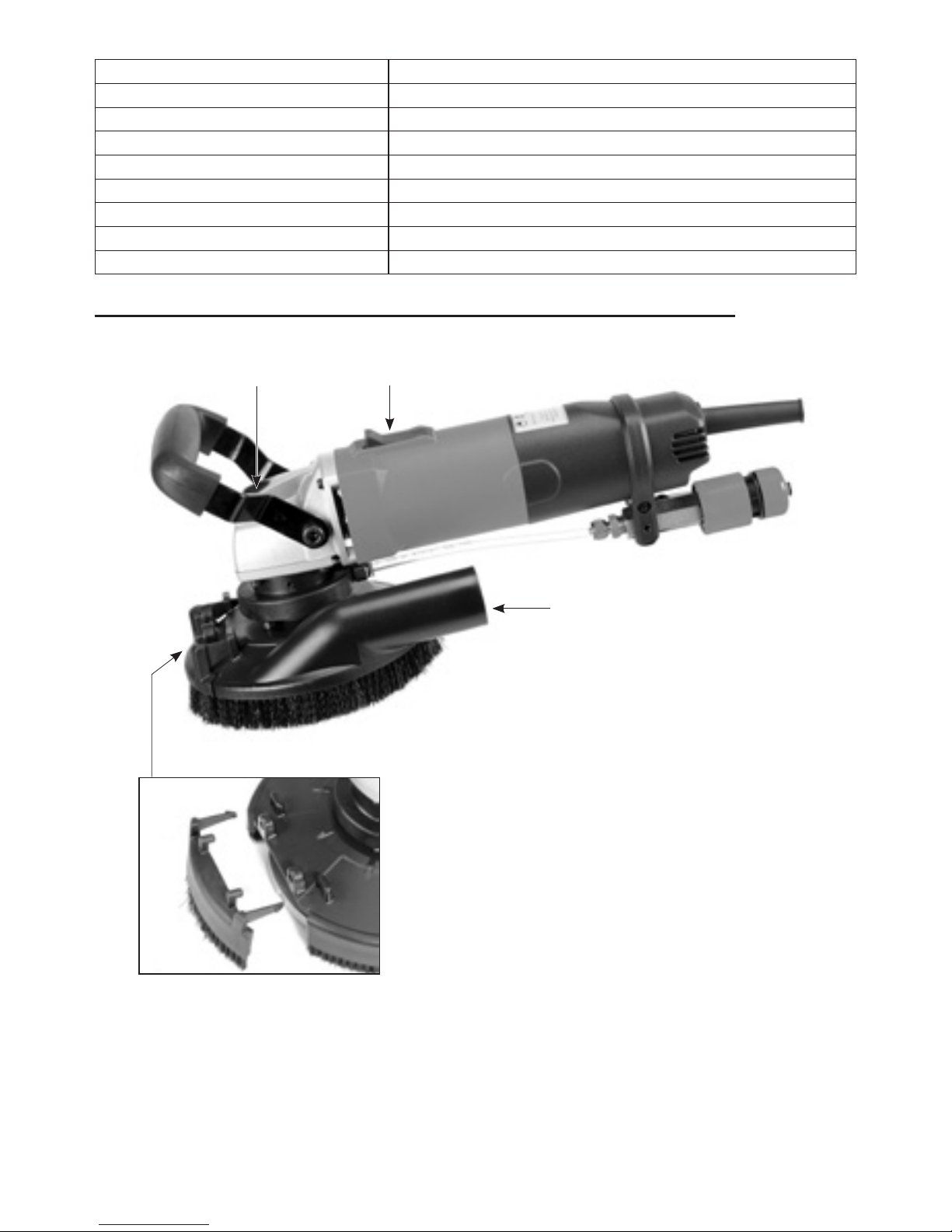
5" Dust Collect Cover Mode
Vacuum port
Spindle Lock On / Off Switch
Half-moon door

4
Model 7" Wet-Dry mode 7" Dust Collect Cover Mode
Power input 2500W
Voltage See machine nameplate
No Load min-1 1000 ~ 2400
Spindle M14
Max. Disc Diameter 7" (180mm)
Soft Start & Overload Protection With
Dimensions 500mm ( L ) X 210mm ( W ) X 200mm ( H )
Net Weight 5.8 kg (12.76bs) 6.00 kg (13.2Lbs)
7" Dust Collect Cover Mode
7" Wet-Dry Mode
Trigger Switch
Variable Speed Wheel
Quick-release
water hose
coupling
Quick change conversion
to wet or dry
Front Handle
Spindle Lock
Vacuum port
Diamond plate (not included)
Half-moon door

5
GENERAL SAFETY RULES
WARNING! Read and understand all
instructions. Failure to follow all instructions
listed below, may result in electric shock,
fire and / or serious personal injury. The term
“power tool” in all of the warnings listed
below refers to your mains-operated
(corded) power tool.
SAVE THESE INSTRUCTIONS.
■ Work area safety
Keep your work area clean and well lit.
Cluttered worksites and dark areas invite
accidents.
Do not operate power tools in explosive
atmospheres, such as in the presence of
flammable liquid, gases, or dust. Power
tools create sparks which may ignite the
dust or fumes.
Keep bystanders, children, and visitors
away while operating a power tool.
Distractions can cause you to lose control.
■ Electrical Safety
Grounded tools must be plugged into an
outlet properly installed and grounded in
accordance with all codes and ordinances.
Never remove the grounding prong or
modify the plug in any way. Do not use any
adaptor plugs. Check with a qualified
electrician if you are in doubt as to whether
the outlet is properly grounded. If the tools
should electrically malfunction or break
down, grounding provides a low resistance
path to carry electricity away from the user.
Avoid body contact with grounded
surfaces such as pipes, radiators, ranges
and refrigerators. There is an increased risk
of electric shock if your body is grounded.
Don’t expose power tools to rain or wet
conditions. Water entering a power tool will
increase the risk of electric shock.
Don’t abuse the cord. Never use the cord to
carry the tools or pull the plug from an
outlet. Keep cord away from heat, oil, sharp
edges or moving parts. Replace damaged
cords immediately. Damaged cords
increase the risk of electric shock.
When operating a power tool outside, use
an outdoor extension cord marked “W-A”
or “W.” These cords are rated for outdoor
use and reduce the risk of electric shock.
■ Personal Safety
Stay alert, watch what you are doing and
use common sense when operating a
power tool. Do not use tool while tired or
under the influence of drugs, alcohol, or
medication. A moment of inattention while
operating power tools may result in serious
personal injury.
Use safety equipment. Always wear eye
protection. Safety equipment such as dust
mask, non-skid safety shoes, hard hat, or
hearing protection used for appropriate
conditions will reduce personal injuries.
Avoid accidental starting. Be sure switch is
off before plugging in. Plugging in tools that
have the switch on invites accidents.

6
Remove adjusting keys or switches before
turning the tool on. A wrench or a key that is
left attached to a rotating part of the tool
may result in personal injury.
Do not overreach. Keep a proper footing
and balance at all times. Proper footing
and balance enables better control of the
tool in unexpected situations.
Dress properly. Do not wear loose clothing
or jewelry. Keep your hair, clothing and
gloves away from moving parts. Loose
clothes, jewelry or long hair can be caught
in moving parts.
■ Tool use and care
Do not force tool. Use the correct tool for
your application. The correct tool will do
the job better and safer at the rate for
which it is designed.
Do not use tool if switch does not turn it on
or off. Any tool that cannot be controlled
with the switch is dangerous and must be
repaired.
Disconnect the plug from the power source
before making any adjustments, changing
accessories, or storing the tool. Such
preventive safety measures reduce the risk
of starting the tool accidentally.
Store idle tools out of reach of children and
do not allow persons unfamiliar with the
power tool or these instructions to operate
the power tool. Tools are dangerous in the
hands of untrained users.
Maintain tools with care. Properly
maintained tools are less likely to bind and
are easier to control.
Check for misalignment or binding of
moving parts, breakage of parts, and any
other condition that may affect the tools
operation. If damaged, have the tool
serviced before using. Many accidents are
caused by poorly maintained tools.
Use the power tool, accessories and blades
etc., in accordance with these instructions
and in the manner intended for the
particular type of power tool, taking into
account the working conditions and the
work to be performed. Use of the power
tool for operations different from those
intended could result in a hazardous
situation.
■ Service
Have your tool serviced by a qualified
repair person using only identical
replacement parts. This will ensure that the
safety of the power tool is maintained.
-WARNING- To reduce the risk of injury, user
must read instruction manual.
Symbols used in this manual
V……...volts
A……...amperes
Hz……..hertz
W……...watt
~………alternating current
n0…… .no load speed
min-1… .revolutions or reciprocation
per minute
…… .class II tool

7
SPECIFIC SAFETY RULES
1. Keep hands away from rotating disc
area at all times!
2. Prolonged breathing of airborne dust
from grinding operations may effect
respiratory function:
Always use a vacuum cleaner with a
bag approved for fine dust installed.
Always wear a respirator approved for
dust and mist.
3. Grinding LEAD-BASED paint is
extremely toxic and should not be
attempted. Only allow professionals
with special training and equipment
perform this task.
4. Maintain proper footing and balance
at all times. Do not overreach.
5. Always wear appropriate safety
equipment when operating.
6. Important: After completing operation,
switch off the switch and wait for the
coasting disc to stop completely
before putting the tool down.
7. Never operate the tool in an area with
flammable solids, liquids, or gases.
Sparks from the commutator/carbon
brushes could cause a fire or explosion.
8. There are certain applications for
which this tool was designed. The
manufacturer strongly recommends
that this tool NOT be modified and/or
used for any application other than for
which it was designed. If you have any
questions relative to its application DO
NOT use the tool until you have written
the manufacturer and have been
advised.
9. Use the machine with both hands at all
times. Loss of control can cause
personal injury.
10. Keep power supply cord clear from the
working range of the machine. Always
lead the cable away behind you.
11. Immediately switch off the machine if
unusual vibrations or if other
malfunctions occur. Check the
machine in order to find out the cause.
12. The dust that arises when working with
this tool can be harmful to health. Use
a dust absorption system and wear a
suitable dust protection mask and
remove deposited dust with a vacuum
cleaner.
■ FUNCTIONAL DESCRIPTION
This Stone Grinder is designed for finish
grinding of stone. Various grits of hook &
loop backed diamond polishing pads are
available for this purpose..
■ Electrical connection
The network voltage must conform to the
voltage indicated on the tool name plate.
Under no circumstances should the tool be
used when the power supply cable is
damaged.
A damaged cable must be replaced
immediately by a qualified Customer
Service Center. Do not try to repair the
damaged cable yourself. The use of
damaged power cables can lead to an
electric shock.
8
■ Extension cable
If an extension cable is required, it must
have a sufficient cross-section so as to
prevent an excessive drop in voltage or
overheating. An excessive drop in voltage
reduces the output and can lead to failure
of the motor. The following table shows you
the correct cable diameter as a function of
the cable length for this machine. Use only
approved extension cables. Never use two
extension cables together. Instead, use one
long one.
■ UNPACKING
Carefully remove the tool and all loose
items from the shipping container.
Retain all packing materials until after you
have inspected and satisfactorily operated
the machine.
■ CARTON CONTENTS
1. Stone Grinder machine
2. Instruction manual
3. Side handle
4. 125mm backing plate
DO NOT OPERATE THIS TOOL UNTIL YOU
READ AND UNDERSTAND THE ENTIRE
INSTRUCTION MANUAL
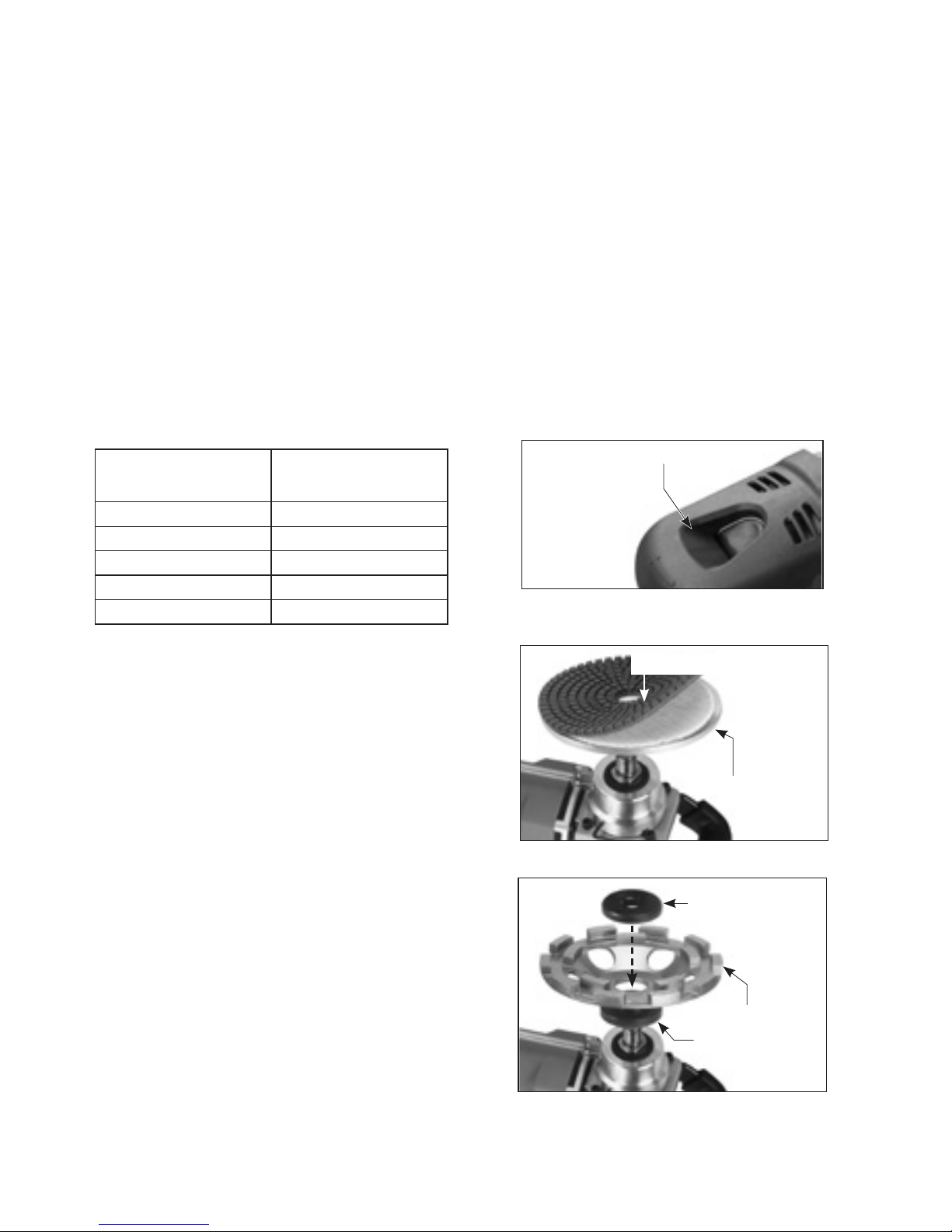
■5"&7", To install a the Backing Plate and
Diamond Polishing Pad, Diamond Plate
1. Unplug the machine.
2. Thread on the Backing Plate onto the
arbor. Press the Spindle Lock and
rotate the arbor until it engages.
Tighten backing plate.
3. Select the desired grit of diamond
polishing pad (not included) and
adhere to the Backing Plate by
pressing together the hook & loop
backings.
4. Removal is the opposite of assembly.
Total Extension Cord Size (AWG)
Cord Length (feet)
25 16
50 12
100 10
150 8
200 6
Spindle Lock
Backing Plate
Diamond Polishing Pad
Out flange
Diamond Plate
Inner flange

9
5" Dust Collect Cover Mode
7" Dust Collect Cover Mode
SPECIAL INSTRUCTIONS FOR WATER FEED
EQUIPPED MACHINES
Water feed models provide water directly
to the workpiece.
WARNING: Never allow water to enter the
motor or its power supply cord!
Electrocution could result!
To install, attach the quick-release Water
Coupling to your water supply hose.
Connect the coupling to the Water Nipple.
Regulate the water flow to the desired
amount by adjusting the tap at the water
supply.
The Water Feed Collar can be turned to the
desired position by first loosening the 3 set
screws using the supplied L-hex key.
Hoop and loop plate for Diamond polishing
Diamond plate with flanges
Diamond plate with thread
Diamond plate with flanges
Inner flange
Inner flange
Out flange
Out flange

10
The seals in the Water Feed Collar are a
wearing part. When they are worn, water
will be seen to leak out of the top or
bottom of the collar. At this point, the seals
must be replaced. To replace, loosen the 3
set screws to remove the Water Feed
Collar, drive out the old seals and press in
new ones.
■ STARTING AND STOPPING TOOL
Make sure that the power circuit voltage is
the same as that shown on the
specification plate of the machine and
that switch is “OFF” before connecting the
tool to the power circuit.
■ Switching the machine on and off
(5" Dry Mode (High/Low Speed Mode )
( 5" Wet-Dry Mode)
(5" Dust Collect Cover Mode)
To switch on:
While holding with the left hand on the side
handle and the right hand on the main
handle, push forward and down on the
Switch Slider until it clicks to the "on"
position. Anticipate and be ready for the
start up torque when the machine first
starts.
WARNING: This is a lock-on switch, so
whenever it is on, it will remain locked on
until you actively turn it off. Before plugging
the tool in, always ensure that the switch is
in the "Off" position. Whenever there is a
power outage, always remember to switch
the tool off. Otherwise, when the power
comes back on, the machine would start
unexpectedly-causing a hazardous
situation.
To switch off:
Press down on the back of the Switch Slider
to release the switch. After the machine
has been switched off, the disc will still
rotate for a time. Take care that parts of
your body do not come into contact with
the disc and do not set the machine down
while it is still rotating!
■ Switching the machine on and off
(7" Wet-Dry Mode)
(7" Dust Collect Cover Mode)
TTo switch on:
While holding with the left hand on the front
grip and the right hand on the main
handle, squeeze the trigger switch to the
"on" position. Anticipate and be ready for
the start up torque when the machine first
starts.
On / Off Switch
seal
L-hex key
Water Feed Collar

11
■ Adjusting the rotation speed:
(7" Wet-Dry Mode)
(7" Dust Collect Cover Mode)
The speed of the machine is variable to suit
different tasks. It can be adjusted from
1000/min up to 2400/min by using the
thumb wheel. turn in the rightward
direction to increase the speed and in the
leftward direction to decrease the speed.
■ The Half-Moon Door
The sanding plate cover is equipped with a
removable half-moon door. This is to allow
the operator to sand right up to the edge
or into a corner.
Dust collection will not be ideal while the
half-moon door is removed, so the door
should only be removed when necessary
and then replaced immediately.
To remove, first shut down the machine and
unplug the power supply cable.
Then press the 2 tangs which retain the half-
moon door just enough to release it and lift
This is a lock-on type switch, so for
continued operation, the locking pin may
be pressed. To shut off, first re-squeeze and
then release the trigger switch to release
the lock.
To switch off:
Release the trigger switch. If the switch has
been locked on, first re-squeeze and then
release the trigger switch to release the
lock. After the machine has been switched
off, the grinding wheel will still rotate for a
time. Take care that parts of your body do
not come into contact with the wheel and
do not set the machine down while it is still
rotating!
■ Adjusting the rotation speed:
(5" Dry Mode (High/Low Speed Mode )
( 5" Wet-Dry Mode)
(5" Dust Collect Cover Mode)
The speed of the machine is variable to suit
different tasks. It can be adjusted from
3,000/min up to 6,500/min for high speed
models, or 1,700/min up to 3,700/min for
low speed models by using the thumb
wheel. turn in the rightward direction to
increase the speed and in the leftward
direction to decrease the speed.
Speed Adjustment
Thumbwheel
On / Off Switch
Lock button
Variable Speed Wheel

12
the door away. Put the door in a safe place
where it will not be lost or damaged when it
is time to replace it.
To replace, line up the locating pins in the
sanding plate cover and snap the tangs in
place.
■ HOW TO USE THE TOOL
Effective control of this machine requires
two-handed operation for maximum safety
and control.
The proper hold is to keep one hand on the
main handle and the other hand on the
grip . It is vitally important to keep stable
footing at all times,
■ GRINDING OPERATIONS
Once the machine is set up and all safety
measures and equipment are in place,
begin by turning on the machine.
Begin working and contact the workpiece.
It is not necessary to use excessive down
force. Allow the machine to work at the
pace it was intended.
■ MAINTENANCE
■ KEEP TOOL CLEAN
Periodically blow out all air passages with
dry compressed air. All plastic parts should
be cleaned with a soft damp cloth. NEVER
use solvents to clean plastic parts. They
could possibly dissolve or otherwise
damage the material.
Wear safety glasses while using compressed
air..
■ THE CARBON BRUSHES
The carbon brushes are a normal wearing
part and must be replaced when they
reach their wear limit.
NOTE: Checking and replacing the carbon
brushes should be entrusted to a qualified
service center.
The carbon brushes furnished will last
approximately 50 hours of running time or
10,000 on/off cycles. Replace both carbon
brushes when either has less than 1/4"
length of carbon remaining.
■ 5"Dry Mode (High/Low Speed Mode )
■ 5" Wet-Dry Mode
■ 5" Dust Collect Cover Mode
To inspect or replace brushes, first unplug
the machine and lay it on its side. Remove
the 2 screws to remove the Tail Cover. Slide
off the Tail Cover.
Using needle-nose pliers, rotate the spiral
spring to relieve the tension on the brush
and slide it out of the holder.
Uplug the female spade connector which
holds the brush lead and remove the
Carbon Brush.
Ensure the slot for the Variable Speed
Wheel is lined up and slide the Tail Cover

13
into place. Then tighten the 2 screws.
■7" Wet-Dry Mode
■7" Dust Collect Cover Mode
To inspect or replace brushes, first unplug
the machine. Carefully remove the 4
screws to separate the rear handle halves
and then remove the 4 screws which
connect the handle to the motor housing.
Lift away the left-hand handle half first.
There will still be wires connected to the
rear handle, so take care that these are not
stressed. Simply hold the rear handle off to
one side. Next remove the two screws
holding on the Electronics Unit to allow
access to the Brush screws. Hold the
Electronics Unit off to one side and avoid
stressing the wires. Rotate the spiral spring
to relieve the tension on the brush and slide
it out of the holder.
Unscrew the two screws which hold the
brush leads and remove the Carbon
Brushes.
NOTE: When putting the Carbon Brushes
back into the Carbon Brush Holders it is
essential that both flanges go back inside
the holder.
NOTE: To reinstall the same brushes, first
make sure the brushes go back in the way
they came out. Otherwise a break-in period
will occur that will reduce motor
performance and increase brush wear.
Replacing is the reverse of removal. When
Replacing all covers, take great care that
all wires are in place and not in a position
to be pinched when they are retightened.
It is recommended that, at least once a
year, you take the tool to an Authorized
Service Center for a thorough cleaning and
lubrication.
■ If the replacement of the power supply
cord is necessary, this has to be done by
the manufacturer or their agent in order to
avoid a safety hazard.
14
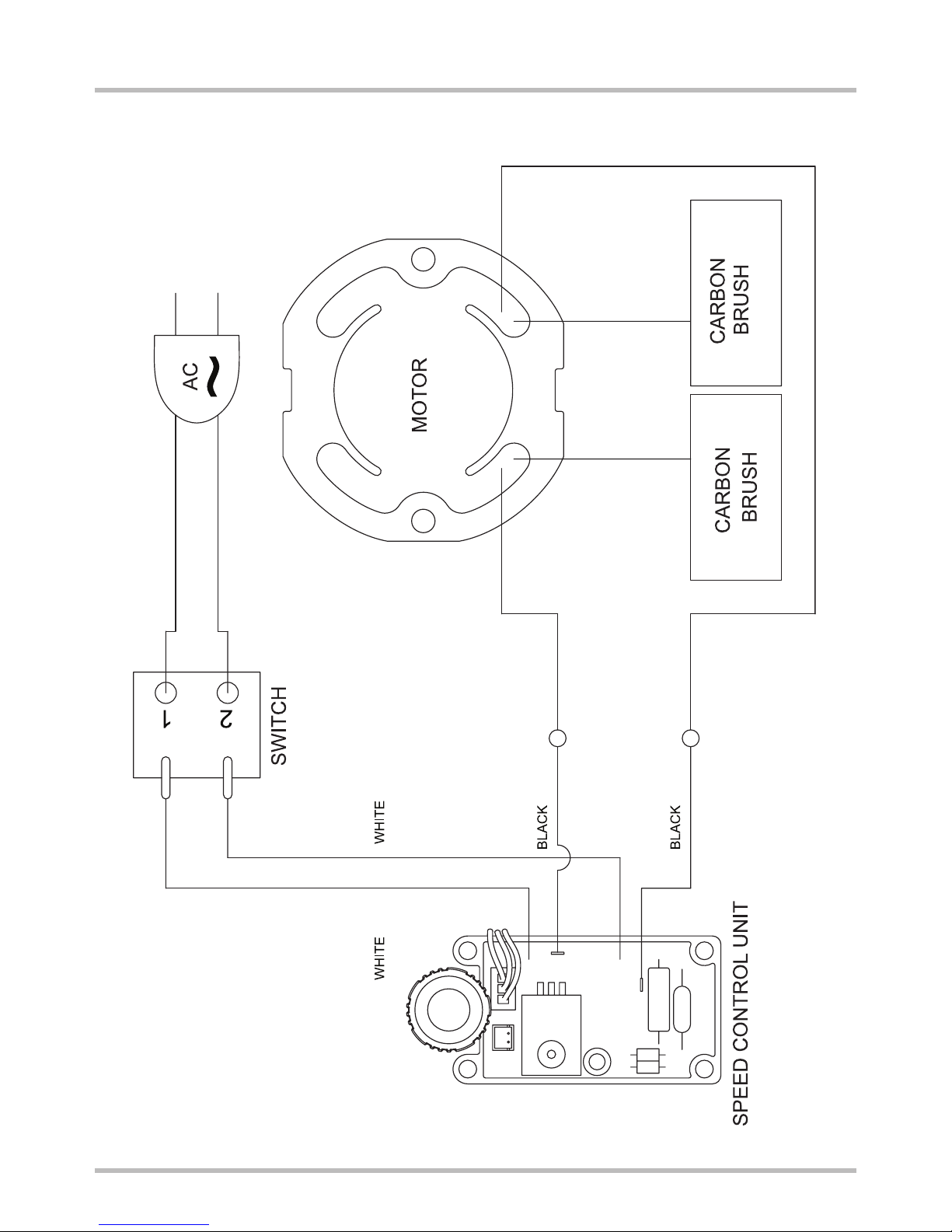
5" Stone Grinders Wiring

15
CARBON
BRUSH
MOTOR
CARBON
BRUSH
BLACK
SPEED CONTROL UNIT
SWITCH
WHITE
BLACK
RED
BLACK
1
1
2
2
AC
GEAR CASE
EARTH
7" Stone Grinders Wiring
16
04
03
05
03
10
09
08
07
11
12
13
14
06
16
15 28
27
26
30
29
32
33
34
35
37
25
24
22
21
20
19
18
17
40
41
38
42
43
03
44
02
36A
01A
39
56
55
56
59
03
54
53
A4
58
OPTIONAL
B4 B5
B3B1 B2
A1
A2
A3
OPTIONAL
A
B
G
K
C
DJ
F
L
H
E
I
36B
31A
31B
HIGH SPEED
LOW SPEED
23A
23B
HIGH SPEED
LOW SPEED
60
57
01B
26
45
45
48
49
50
51
66
65
67
69
68
70
=A+B+C+D+E+(F)
=A+G+H+I+J+(L)
=A+G+H+I+J+K+(L)
(5"W) 5" High speed mode
=A+B+C+D+E+(F)
(5" L) 5" Low speed mode
(5" LF) 5" Dust Collect Cover Mode
(5" LFB) 5" Dust Collect Cover Mode
(Half-moon)
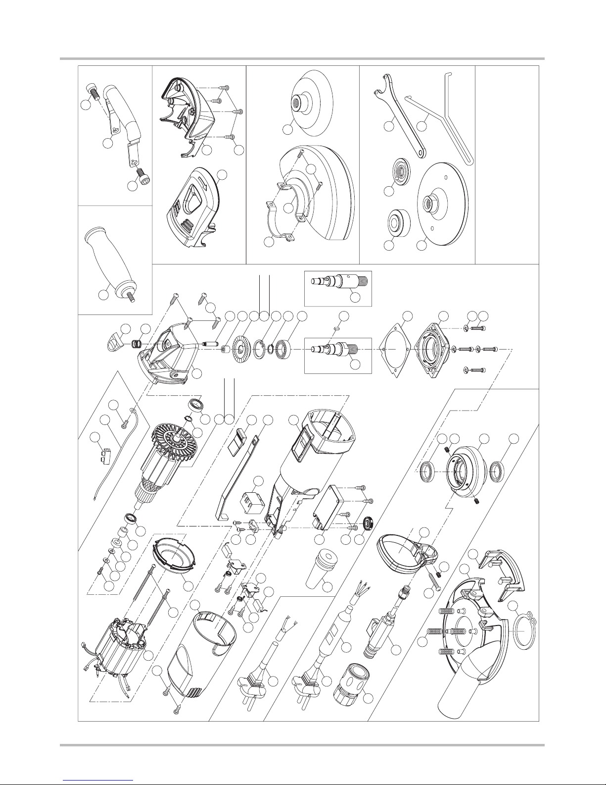
5" Stone Grinders Exploded View

17
5" Stone Grinders Parts List
NO. Parts Name 5"W 5"L 5"LF 5"LFB
1A POWER SUPPLY CABLE 1 1 NA NA
1B POWER SUPPLY CABLE NA NA 1 1
2 CORD ARMOR 1 1 1 1
3 SCREW M4 x 16 12 12 8 8
4 ELECTRONICS BOARD 1 1 1 1
4 ELECTRONICS BOARD 1 1 1 1
5 CABLE CLIP 1 1 1 1
6 TAIL COVER 1 1 1 1
7 SCREW M4 x 10 4 4 4 4
8 SPIRAL TORSION SPRING 2 2 2 2
9 CARBON BRUSH 7 x 11 + 33L + FLDNBI-1102 2 2 2
10 CARBON BRUSH HOLDER 2 2 2 2
11 SWITCH 1 1 1 1
12 SWITCH SLIDER 1 1 1 1
13 SWITCH LEVER 1 1 1 1
14 MOTOR HOUSING 1 1 1 1
15 STATOR 1 1 1 1
15 STATOR 1 1 1 1
16 STATOR SCREW M4 x 60 2 2 2 2
17 SCREW M4 x 10 1 1 1 1
18 FLAT WASHER ø4 x ø10 x 1 1 1 1 1
19 PLASTIC WASHER ø4 x ø11 x 1 1 1 1 1
20 PICKUP MAGNET ø8 x ø15 x 5 1 1 1 1
21 SPACER ø8 x ø12 x 10.5 1 1 1 1
22 BEARING 608-2RU 1 1 1 1
23A ARMATURE-HIGH SPEED M1.2 x 8T H* 1 NA NA NA
23B ARMATURE-LOW SPEED M1.15 x 6T L* NA 1 1 1
24 BEARING 6001-2RS 1 1 1 1
25 GEAR CASE 1 1 1 1
26 SCREW M4 x 25 4 4 5 5
27 SPINDLE LOCK BUTTON 1 1 1 1
5"W------ 5" High speed mode
5" L ------ 5" Low speed mode
5"LF ----- 5 " Wet-Dry mode
5"LFB----- 5" Dust Collect Cover Mode
H*-------- High Speed
L*--------- Low Speed

18
NO. Parts Name 5"W 5"L 5"LF 5"LFB
28 COIL SPRING ø0.9 x ø10 x ø11.8 x 13.5L x 4T 1 1 1 1
29 SPINDLE LOCK 1 1 1 1
30 NEEDLE BEARING HK 0810 1 1 1 1
31A BEVEL GEAR-HIGH SPEED M1.2 x 33T H* 1 NA NA NA
31B BEVEL GEAR-LOW SPEED M1.15 x 43T L* NA 1 1 1
32 INTERNAL CIRCLIP R-35 1 1 1 1
33 EXTERNAL CIRCLIP S-15 1 1 1 1
34 BEARING 6202-2RS 1 1 1 1
35 PARALLEL KEY 3 x 3 x 8 1 1 1 1
36A SPINDLE M14 1 1 NA NA
36B SPINDLE M14 NA NA 1 1
37 GEAR PLATE 1 1 1 1
38 SCREW M4 x 16 4 4 4 4
39 SIDE HANDLE 1 1 NA NA
40 THUMB WHEEL 1 1 1 1
41 GASKET 1 1 1 1
42 SPRING WASHER M4 4 4 4 4
43 EXTERNAL CIRCLIP S-12 1 1 1 1
44 FAN SHROUD 1 1 1 1
45 OIL SEAL ø20 x ø30 x 5 NA NA 2 2
46 N/A NA NA NA NA
47 N/A NA NA NA NA
48 HOSE BRACKET NA NA 1 1
49 SCREW M5 x 6 NA NA 1 1
50 WATER FEED CONNECTOR KIT NA NA 1 1
51 WATER COUPLING NA NA 1 1
52 N/A NA NA NA NA
53 GEARBOX COVER - UPPER 1 1 NA NA
54 GEARBOX COVER - LOWER 1 1 NA NA
55 HANDLE NA NA 1 1
56 SCREW M8 x 16 NA NA 2 2
5" Stone Grinders Parts List
5"W------ 5" High speed mode
5" L ------ 5" Low speed mode
5"LF ----- 5 " Wet-Dry mode
5"LFB----- 5" Dust Collect Cover Mode
H*-------- High Speed
L*--------- Low Speed

19
NO. Parts Name 5"W 5"L 5"LF 5"LFB
57 OVERLOAD PROTECTION NA NA 1 1
58 EARTH WIRE 20# 25cm + 4R x 10 NA NA 1 1
59 SCREW M4 x 8 NA NA 1 1
60 TERMINAL 2/12 NA NA 1 1
61 DUST SHROUD NA NA NA 1
62 SCREW M5 x 20 NA NA NA 1
63 RING ø5.1 x ø8 x 4 NA NA NA 1
64 HEX NUT M5 NA NA NA 1
65.) WATER FEED COLLAR NA NA NA 1
66 SET SCREW M5 x 6 NA NA NA 3
67 SPRING ø0.6 x ø6 x ø7.2 x 10T x 20L NA NA NA 4
68 SANDING PLATE COVER NA NA NA 1
69 HALF-MOON DOOR NA NA NA 1
70 INTERNAL CIRCLIP S-45 NA NA NA 1
(Optional for model 5"W & 5"L)
A1 SCREW M5 x 12 2 2 NA NA
A2 GUARD 1 1 NA NA
A3 GUARD BRACKET 1 1 NA NA
A4 4" SANDING PAD 4" 1 1 NA NA
(Optional for model 5"LF & 5"LFB)
B1.) INNER FLANGE NA NA 1 1
B2 ARBOR NUT NA NA 1 1
B3 WRENCH NA NA 1 1
B4 ALUMINUM CUP WHEEL NA NA 1 1
B5 FACE SPANNER WRENCH NA NA 1 1
5" Stone Grinders Parts List
5"W------ 5" High speed mode
5" L ------ 5" Low speed mode
5"LF ----- 5 " Wet-Dry mode
5"LFB----- 5" Dust Collect Cover Mode
H*-------- High Speed
L*--------- Low Speed

20
7" Stone Grinders Exploded View
21
20
19
18
22
11
10
16
17
14
15
17
16
15
1412
23
24
25
26
27
28
29
31
37
36
38
34
33
32
35
44
43
42
41
40
53
53
52
13
13
02
01
03
04
05
06
54
07
08
09
55
56
06
39
60
59
56
61
62
57
58
OPTIONAL
A1
A2 A4
A3
45
45
70
48
49
50
68
73
72
74
51
71
67
FOR EP7FB
This manual suits for next models
1
Table of contents
Other TRAXX Grinder manuals


Popular Grinder manuals by other brands

SUHNER ABRASIVE
SUHNER ABRASIVE LFB 44-E Technical document

Parkside
Parkside PFBS 9.6 A1 Operation and safety notes

Berner
Berner BBG 150 instruction manual

Huskie Tools
Huskie Tools HTP-AGR Operating instructions manual

Bosch
Bosch GWS Professional 22-180 JH Original instructions

Bosch
Bosch GSS 140 A Professional Original instructions


Würth
Würth EWS 7-115 BASIC Translation of the original operating instructions

DeWalt
DeWalt DW802G instruction manual

Central Machinery
Central Machinery 94186 Assembly and operating instructions

Proxxon
Proxxon LBS/E manual

Bosch
Bosch 8-125 CE Original instructions

Graphite
Graphite 59G062 Translation of the original instructions