TRAXX BG5 User manual

Unit 4/1 Rocklea Drive
Port Melbourne Vic 3207
1300 109 108
www.traxxcp.com.au
BG5 HIGH FREQUENCY CONCRETE GRINDER
& P4000 POWER CONVERTER
OPERATIONS MANUAL
ORIGINAL INSTRUCTIONS
For your personal safety, READ and UNDERSTAND before using,
SAVE THESE INSTRUCTIONS FOR FUTURE REFERENCE
BG5 HIGH FREQUENCY GRINDER
P4000 POWER CONVERTER

2
1. Motor
2. Load Warning Lamp
3. Trigger Switch
4. Handles
5. Lugs (for Trolley)
6. Dust Port
7. Skirt
8. Tab
9. Half-Moon Door
10. Coupling Cable
11. Motor Coupling Socket
12. Handle
13. Screen
14. Power Button
15. Selection Buttons
16. Power Supply Cable
1.
Concrete Grinder:
Power Converter:
Model Concrete Grinder
Power Input 3~ 2200W
No Load/min
-1
3850 - 5800
Wheel Diameter 125mm (5")
Arbor 22.23mm (7/8") & 25.4 (1") (Double-Sided)
Spindle M14 or 5/8-11 ( Specify when ordering)
Ingress Protection IP55
Dimensions (LxWxH) 235mm x 290mm x 235mm
Weight 5.1kg (11.3 Lbs)
Model Power Converter
Voltage 100V - 240V ~ 50-60Hz
Max. Power Input 1~ 4500W
Max. Power Output 3~ 4000W
Ingress Protection IP55
Weight 3.1kg (6.9 Lbs)
2.
3.
5.
6. 7.
4.
10.
11.
12.
16.
15.
13.
14.
9.
8.

3
General Safety Rules
WARNING! Read all safety warnings and all instructions. Failure to follow the warnings and
instructions may result in electric shock, re and/or serious injury.
Save all warnings and instructions for future reference.
The term “power tool” in the warnings refers to your mains-operated (corded) power tool or battery-operated
(cordless) power tool.
1. WORK AREA SAFETY
a. Keep work area clean and well lit. Cluttered and dark areas invite accidents.
b. Do not operate power tools in explosive atmospheres, such as in the presence of fl ammable
liquids, gases or dust. Power tools create sparks which may ignite the dust or fumes.
c. Keep children and bystanders away while operating a power tool. Distractions can cause you to lose
control.
d. Never leave the electric power tool unattended. Only leave the machine when the tool in use has come
to a complete standstill.
2. ELECTRICAL SAFETY
a. Power tool plugs must match the outlet. Never modify the plug in any way. Do not use any adapter
plugs with earthed (grounded) power tools. Unmodi ed plugs and matching outlets will reduce risk of
electric shock.
b. Avoid body contact with earthed or grounded surfaces, such as pipes, radiators, ranges and
refrigerators. There is an increased risk of electric shock if your body is earthed or grounded.
c. Do not expose power tools to rain or wet conditions. Water entering a power tool will increase the risk
of electric shock.
d. Do not abuse the cord. Never use the cord for carrying, pulling or unplugging the power tool. Keep
cord away from heat, oil, sharp edges or moving parts. Damaged or entangled cords increase the risk
of electric shock.
e. When operating a power tool outdoors, use an extension cord suitable for outdoor use. Use of a
cord suitable for outdoor use reduces the risk of electric shock.
f. If operating a power tool in a damp location is unavoidable, use a residual current device (RCD)
protected supply. Use of an RCD reduces the risk of electric shock.
3. PERSONAL SAFETY
a. Stay alert, watch what you are doing and use common sense when operating a power tool. Do
not use a power tool while you are tired or under the in uence of drugs, alcohol or medication. A

4
moment of inattention while operating power tools may result in serious personal injury.
b. Use personal protective equipment. Always wear eye protection. Protective equipment such as dust
mask, non-skid safety shoes, hard hat, or hearing protection used for appropriate conditions will reduce
personal injuries.
c. Prevent unintentional starting. Ensure the switch is in the o-position before connecting to power
source and/or battery pack, picking up or carrying the tool. Carrying power tools with your nger on
the switch or energising power tools that have the switch on invites accidents.
d. Remove any adjusting key or wrench before turning the power tool on. A wrench or a key left
attached to a rotating part of the power tool may result in personal injury.
e. Do not overreach. Keep proper footing and balance at all times. This enables better control of the
power tool in unexpected situations.
f. Dress properly. Do not wear loose clothing or jewellery. Keep your hair and clothing away from
moving parts. Loose clothes, jewellery or long hair can be caught in moving parts.
g. If devices are provided for the connection of dust extraction and collection facilities, ensure these
are connected and properly used. Use of dust collection can reduce dustrelated hazards.
h. Do not let familiarity gained from freuquent use of tools allow you to become complacent and
ignore tool safety principles. A careless action can cause severe injury within a fraction of a second.
4. POWER TOOL USE AND CARE
a. Do not force the power tool. Use the correct power tool for your application. The correct power tool
will do the job better and safer at the rate for which it was designed.
b. Do not use the power tool if the switch does not turn it on and o. Any power tool that cannot be
controlled with the switch is dangerous and must be repaired.
c. Disconnect the plug from the power source and/or battery pack from the power tool before making
any adjustments, changing accessories, or storing power tools. Such preventive safety measures
reduce the risk of starting the power tool accidentally.
d. Store idle power tools out of the reach of children and do not allow persons unfamiliar with the
power tool or these instructions to operate the power tool. Power tools are dangerous in the hands of
untrained users.
e. Maintain power tools and accessories. Check for misalignment or binding of moving parts,
breakage of parts and any other condition that may aect the power tool‘s operation. If damaged,
have the power tool repaired before use. Many accidents are caused by poorly maintained power tools.
f. Keep cutting tools sharp and clean. Properly maintained cutting tools with sharp cutting edges are less
likely to bind and are easier to control.
g. Use the power tool, accessories and tool bits etc. in accordance with these instructions taking into
account the working conditions and the work to be performed. Use of the power tool for operations
dierent from those intended could result in a hazardous situation.
h. Keep handles and grasping surfaces dry, clean and free of oil and grease. Slippery handles do not
allow for safe handling and control of the tool in unexpected situations.

5
5. SERVICE
a. Have your power tool serviced by a quali ed repair person using only identical replacement parts.
This will ensure that the safety of the power tool is maintained.
b. Only use original Festool parts for repair and maintenance. The use of incompatible accessories or
spare parts can result in electric shocks or other injuries.
Safety Warnings for Concrete Grinders
Safety Warnings Common for Grinding
• This power tool is intended to function as a grinder. Read all safety warnings, instructions,
illustrations and specications provided with this power tool. Failure to follow all instructions listed
below may result in electric shock, re and/or serious injury.
• Operations such as sanding, wire brushing, polishing or cutting-o are not recommended to be
performed with this power tool. Operations for which the power tool was not designed may create a
hazard and cause personal injury.
• Do not use accessories which are not specifically designed and recommended by the tool
manufacturer. Just because the accessory can be attached to your power tool, it does not assure safe
operation.
• The rated speed of the accessory must be at least equal to the maximum speed marked on the
power tool. Accessories running faster than their rated speed can break and y apart.
• The outside diameter and the thickness of your accessory must be within the capacity rating of
your power tool. Incorrectly sized accessories cannot be adequately guarded or controlled.
• Threaded mounting of accessories must match the grinder spindle thread. For accessories mounted
by anges, the arbour hole of the accessory must t the locating diameter of the ange. Accessories
that do not match the mounting hardware of the power tool will run out of balance, vibrate excessively
Symbols used in this manual
V…….........volts
A…….........amperes
Hz…….......hertz
W……........watt
~………....alternating current
n
………...rated speed
min-1….......revolutions or reciprocation
per minute
.........warning of general danger
.…..class II tool
.......read these instructions
......always wear eye protection
......always wear a dust mask.
.....always wear hearing protection
.....wear safety-approved hard hat
do not dispose of electric tools,
accessories and packaging together
with household waste material

6
and may cause loss of control.
• Do not use a damaged accessory. Before each use inspect the accessory such as abrasive wheels for
chips and cracks, backing pad for cracks, tear or excess wear, wire brush for loose or cracked wires.
If power tool or accessory is dropped, inspect for damage or install an undamaged accessory. After
inspecting and installing an accessory, position yourself and bystanders away from the plane of
the rotating accessory and run the power tool at maximum no-load speed for one minute. Damaged
accessories will normally break apart during this test time.
• Wear personal protective equipment. Depending on application, use face shield, safety goggles
or safety glasses. As appropriate, wear dust mask, hearing protectors, gloves and workshop apron
capable of stopping small abrasive or workpiece fragments. The eye protection must be capable of
stopping ying debris generated by various operations. The dust mask or respirator must be capable of
ltrating particles generated by your operation. Prolonged exposure to high intensity noise may cause
hearing loss.
• Keep bystanders a safe distance away from work area. Anyone entering the work area must wear
personal protective equipment. Fragments of workpiece or of a broken accessory may y away and
cause injury beyond immediate area of operation.
• Hold the power tool by insulated gripping surfaces only, when performing an operation where the
cutting accessory may contact hidden wiring or its own cord. Cutting accessory contacting a “live” wire
may make exposed metal parts of the power tool “live” and could give the operator an electric shock.
• Position the cord clear of the spinning accessory. If you lose control, the cord may be cut or snagged
and your hand or arm may be pulled into the spinning wheel.
• Never lay the power tool down until the accessory has come to a complete stop. The spinning wheel
may grab the surface and pull the power tool out of your control.
• Do not run the power tool while carrying it at your side. Accidental contact with the spinning
accessory could snag your clothing, pulling the accessory into your body.
• Regularly clean the power tool’s air vents. The motor’s fan will draw the dust inside the housing and
excessive accumulation of powdered metal may cause electrical hazards.
• Do not operate the power tool near ammable materials. Sparks could ignite these materials.
• Do not use accessories that require liquid coolants. Using water or other liquid coolants may result in
electrocution or shock.
Kickback and related warnings
• Kickback is a sudden reaction to a pinched or snagged rotating wheel, backing pad, brush or any other
accessory. Pinching or snagging causes rapid stalling of the rotating accessory which in turn causes the
uncontrolled power tool to be forced in the direction opposite of the accessory’s rotation at the point
of the binding. For example, if an abrasive wheel is snagged or pinched by the workpiece, the edge of
the wheel that is entering into the pinch point can dig into the surface of the material causing the wheel
to climb out or kick out. The wheel may either jump toward or away from the operator, depending on
direction of the wheel’s movement at the point of pinching. Abrasive wheels may also break under
these conditions. Kickback is the result of power tool misuse and/or incorrect operating procedures or
conditions and can be avoided by taking proper precautions as given below.
• Maintain a firm grip on the power tool and position your body and arm to allow you to resist
kickback forces. Always use auxiliary handle, if provided, for maximum control over kickback or
torque reaction during start-up. The operator can control torque reactions or kickback forces, if proper
precautions are taken.

7
• Never place your hand near the rotating accessory. Accessory may kickback over your hand.
• Do not position your body in the area where power tool will move if kickback occurs. Kickback will
propel the tool in direction opposite to the wheel’s movement at the point of snagging.
• Use special care when working corners, sharp edges, etc. Avoid bouncing and snagging the
accessory. Corners, sharp edges or bouncing have a tendency to snag the rotating accessory and cause
loss of control or kickback.
• Do not attach a saw chain woodcarving blade or toothed saw blade. Such blades create frequent
kickback and loss of control.
Additional safety instructions for grinding
• Use only wheel types that are recommended for your power tool and the specic guard designed
for the selected wheel. Wheels for which the power tool was not designed cannot be adequately
guarded and are unsafe.
• The grinding surface of the centre depressed wheels must be mounted below the plane of the
guard lip. An improperly mounted wheel that projects through the plane of the guard lip cannot be
adequately protected.
• The guard must be securely attached to the power tool and positioned for maximum safety, so the
least amount of wheel is exposed towards the operator. The guard helps to protect operator from
broken wheel fragments, accidental contact with wheel and sparks that could ignite clothing.
• Wheels must be used only for recommended applications. For example: do not grind with the side
of the cut-o wheel. Abrasive cut-o wheels are intended for peripheral grinding; side forces applied to
these wheels may cause them to shatter.
• Always use undamaged wheel anges that are of correct size and shape for your selected wheel.
Proper wheel anges support the wheel thus reducing the possibility of wheel breakage. Flanges for cut-
o wheels may be dierent from grinding wheel anges.
• Do not use worn down reinforced wheels from larger power tools. Wheels intended for larger power
tools are not suitable for the higher speed of a smaller tool and may burst.
ELECTRICAL CONNECTION
The network voltage must conform to the voltage indicated on the tool name plate. Under no
circumstances should the tool be used when the power supply cable is damaged. A damaged cable
must be replaced immediately by an authorized Customer Service Center. Do not try to repair the
damaged cable yourself. The use of damaged power cables can lead to an electric shock.
WARNING: Never operate a damaged machine. Always tag a damaged machine and take it out of
service until repairs can be made.
SAFETY SYMBOLS
CAUTION: Indicates a potentially hazardous situation, which, if not avoided may result in minor or
moderate injury. It may also be used to alert against unsafe practices that may cause property damage.
DANGER: Indicates an imminently hazardous situation which if not avoided will result in death or
serious injury.

8
WARNING: Indicates a potentially hazardous situation which if not avoided will result in death or serious
injury.
BEFORE USING THIS TOOL
WARNING: Some dust created by the power sanding, sawing, grinding, drilling and other construction
activities contains chemicals known to cause cancer, birth defects or other reproductive harm. Some
examples of these chemicals are:
• Lead from lead-bases paints
• Crystalline silica from bricks, cement and other masonry products
• Arsenic and chromium from chemically treated lumber.
Your risk from these exposures varies, depending on how often you do this type of work. To reduce your
exposure to these chemicals, work in a well-ventilated area and work with approved safety equipment such as
dust masks specially designed to filter out microscopic particles.
UNPACKING
Remove the tool and all loose parts from the carton. Place all parts on a secure, stationary work surface and
look the machine over carefully.
LIST OF PARTS
List of Contents
Basic Assembly....................................1
Operator’s Manual.............................1
Lock Nut Wrench................................1
Face Spanner Wrench.......................1
L-Hex Wrench.......................................1
Flanges...................................................2
INTRODUCTION
This machine is a special, high-frequency, PMSM power tool (permanent magnet synchronous motor). It must
be only be used with its special power converter, which acts as a motor controller.
The converter also provides variable speed control.
Connection between the converter and motor is made by a motor coupling cable with special plug.
The power converter has overload, thermal, under voltage and over voltage protection.
RECOMMENDED ACCESSORIES
This machine may only be used with diamond cup wheels of 125mm diameter with 25.4mm (1") or 22.23mm
(7/8") arbor hole or with M14 female thread.All other uses are prohibited.
Bonded abrasive accessories are not allowed to be used with this machine.

9
BASIC OPERATION
NOTE: Make sure that the power circuit voltage is the same as that shown on the specification plate of
the machine and that switch is“OFF” before connecting the tool to the power circuit.
Connect the motor to the converter before turning the converter on.
The connection between the power converter and the motor is by a special motor coupling cable. To connect,
unscrew the cap, align the tangs, push in, and screw on the collar. Take care to avoid bending the pins. Keep
the cap on when not in use. Do not alter this plug in any way.
THE SWITCH
The machine has a lockable trigger switch. Squeeze the trigger to
start the machine. To lock the switch on, press the lock button while
holding the trigger switch on.
To release, squeeze the trigger and release.
CAUTION: After the machine has been switched off, the spindle
will continue rotating. Take care that parts of your body do not
come into contact with the rotating parts or set the machine
down while it is still rotating!
HOW TO USE THE TOOL
Effective control of this machine requires two-handed operation for maximum protection and resistance to
the start-up and operating torque. Place the work properly and hold the machine firmly WITH BOTH HANDS
to prevent loss of control, which could cause personal injury. Protect your eyes from injury with safety glasses
or goggles.
OVERLOAD PROTECTION, OVERHEAT PROTECTION
Overload & Load Warning Lamp
When operating within the normal load range, the load warning lamp will glow green.
When full load is reached, the load warning lamp will flash red. If full load is exceeded and sustained for too
long, the motor will shut down and the load warning lamp will glow solid red. In this case, the motor must be
first shut off and then restarted. When this happens, the motor will very likely be near overheating, so it is
also a good idea to run the motor at no load for a few minutes to cool it before continuing.
Overheat Thermal Protection
If the temperature of the motor gets too high, the thermal protection will shut the motor down. The switch
must be first shut off and then restarted. When this happens, do not immediately start working after restarting
the motor. Always run the machine at no load for a few minutes to return to a normal operating temperature
before continuing. (Also see below the section: "POWER CONVERTER LCD SCREEN CODES")
Trigger Switch

10
SPEED STABILIZATION
This machine is equipped with an electronic speed stabilization system which maintains constant speed under
load.
VARIABLE SPEED FUNCTION
The motor's speed can be varied to suit the needs of different work situations. Press the UP and DOWN arrow
buttons on the converter to change the speed.
NOTE: The motor must first be turned OFF before the speed can be adjusted.
The available speeds are as below:
5800 min-1
5500 min-1
5150 min-1
4850 min-1
4500 min-1
4200 min-1
3850 min-1
VACUUM CONNECTION
WARNING: Dust developing while working can be harmful to one’s health.
This machine is designed specifically for dry grinding of concrete and similar materials. It uses dry diamond cup
wheels and must be used with a suitable vacuum cleaner. Never exhaust the dust directly into the
atmosphere.
To attach vacuum hose to Dust Port, hold machine firmly with one hand. Then with a twisting motion push the
vacuum hose onto the Dust Port.
SAFETY GUARD
The Safety Guard (ie. the Skirt) must be used at all times when operating this machine. It is not adjustable. The
Half-Moon Door may be temporarily removed to expose the Edge Cut-Out. See below.
THE EDGE CUT-OUT
When working against a wall or into a corner, the Skirt will prevent
the grinding head from reaching all the way to the edge.
Press the Tab, slide the Half-Moon Door outward to
unlock, then rotate the Half-Moon Door to the side until it clicks.
Edge Cut-Out in Skirt Half-Moon Door
3
2
1
Selection Buttons
Power Button
LED indicator
LCD screeen
11
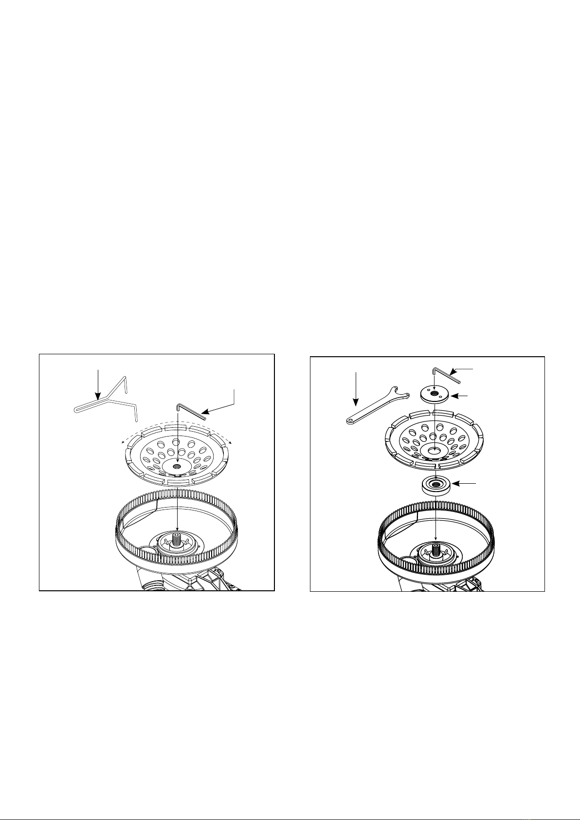
TOOL CHANGE – Removing and Replacing Diamond Cup Wheel
CAUTION: Before Working on or adjusting the machine, switch the machine “OFF”and UNPLUG machine
from the socket.
CAUTION: The wheel can become very hot during the working process. Before replacing, allow the
wheel to cool down
1. Place the machine on a level and sturdy workspace.
2. If using a diamond cup wheel with M14 female thread, do not use the flanges. Simply thread the wheel
onto the spindle. Use the L-Hex Wrench to keep the spindle from turning and tighten the wheel using
the Face Spanner Wrench.
3. If using a diamond cup wheel with arbor hole, first mount the inner flange onto the spindle.
It is 22.23mm on one side and 25.4mm on the other. Mount the wheel onto the shoulder of the Inner
Flange, then thread on the Arbor Nut. Use the L-Hex Wrench to keep the spindle from turning and
tighten the Arbor Nut with the Lock Nut Wrench.
4. Replacement is the opposite of removal.
INSTALLING DIAMOND CUP
WHEELS W/ M14 FEMALE THREAD.
STORAGE
CAUTION: Do not store machine resting on its bristles – Store on its side.
CAUTION: Do not store machine with its power supply cable pinched. This will result in damage to the
cable.
L-Hex Wrench
Arbor Nut
Inner Flange
Lock Nut Wrench
INSTALLING DIAMOND CUP
WHEELS WITH ARBOR HOLE.
Face Spanner Wrench
L-Hex Wrench

12
REPLACING DUST SKIRT BRUSHES
The dust skirt brushes may be replaced when worn. To replace, remove the 3 screws to replace the small brush
on the half moon door and remove the 6 screws to replace the large brush on the dust skirt.
MAINTENANCE
WARNING: To reduce the risk of injury from unexpected starting or electrical shock, unplug the power
cord before working on the machine.
Keep the tool clean. Remove accumulated dust from working parts. Make sure that the tool operates properly.
Periodically check screws and bolts for tightness.
KEEPING TOOL CLEAN
Keep the machine and its air inlet slots clean to ensure correct and safe operation. To clean, blow compressed
air through the air inlet slots with the motor running at no load.
WARNING: If the replacement of the power supply cord is necessary, this has to be done by the
manufacturer or their agent in order to avoid a safety hazard.
Do not throw electric power tools into the household waste! In accordance with the European Directive
2002/96/EG on Waste Electrical and Electronic Equipment and transposition into national law, used
electricpower tools must be collected separately and recycled in an environmentally friendly manner.
OPTIONAL FLOOR GRINDING TROLLEY
This machine has built-in mounting tabs in its handle for mounting to the optional floor
grinding trolley for fatique free grinding of floors. The trolley's 4 spring-loaded
mounting plungers thread into the tabs to suspend the machine.
NOTE: This tool does not use the floor trolley's remote switching function.
CAUTION:
Do not attempt edge grinding with the machine mounted to the floor grinding trolley. The extra
leverage of the trolley will easily damage the dust shroud or turbine housing when it inevitably
contacts the wall. In addition, the range of motion allowed by the floor grinding trolley is not suitable
for edge grinding. Always perform edge grinding in hand-held mode only. Only use the floor grinding
trolley for open areas.

13
POWER CONVERTER LCD SCREEN CODES:
8888
Loss of communication between
the motor electronics board, the
converter electronics board and
the LCD module when powering
up
Check the connection of the coupling cable
E1 Overload of the converter. At the tool, turn the switch OFF and then ON again
E2
Overheat of the converter
As soon as temperature returns to normal, at the tool, turn
the switch OFF and then ON again
E3 Under voltage As soon as supply voltage returns to normal, at the tool,
turn the switch OFF and then ON again
E4 Over voltage As soon as supply voltage returns to normal, at the tool,
turn the switch OFF and then ON
E5 Excessive back voltage from the
motor brake to the converter
At the converter, press the POWER button to turn the power
OFF and then back ON again
(If the problem persists, bring the unit to an authorized
service center for repair)
E6
RCD current leak detection
between the converter and the
voltage supply
Check connections and then, at the converter, press the
POWER button to turn the power OFF and then back ON
again
(If the problem persists, bring the unit to an authorized
service center for repair)
E7 Hall eect sensor error
At the converter, press the POWER button to turn the power
OFF and then back ON again
(If the problem persists, bring the unit to an authorized
service center for repair)
E8
Motor overheat
Allow the motor to cool.
Then, at the tool, turn the switch OFF and then ON again
(If the temperature has sill not dropped suciently, wait
longer for the temperature to drop to the acceptable range)
E91
Loss of communication between
the converter electronics
board and LCD module during
operation
At the converter, try pressing the POWER button to turn
the power OFF and then back ON again. (If the problem
persists, bring the unit to an authorized
service center for repair)
OFF: When the converter is plugged in, the screen will display the supply voltage. The voltage displayed will
depend on the voltage of the supply
ON: When the converter power button is pressed, the tool will be energized and the screen will display
the speed setting. Press the UP or DOWN buttons to adjust the speed setting as required.
ERROR CODES

14
E92
Loss of communication between
the motor electronics board
and the LCD module during
operation
Check the connection of the coupling cable. Then, at the
tool, try turning the switch OFF and then ON again (If the
problem persists, bring the unit to an authorized
service center for repair)
E16
No signal from the motor
temperature sensor
At the tool, try turning the switch OFF and then ON again (If
the problem persists, bring the unit to an authorized service
center for repair)
E17
Motor temperature sensor short
circuited
At the tool, try turning the switch OFF and then ON again (If
the problem persists, bring the unit to an authorized service
center for repair)

15
WIRING
LED
MOTOR
Temperature Sensor
BLACK
BLUE
Brown
BLACK
BLUE
Brown
WIRE
CONNECTOR
BLOCK
ELECTRONICS UNIT
SWITCH
UVW
LCD
DISPLAY
AC
AC N2
AC L2
BRAKING
RESISTOR
BLUE
BROWN
ELECTRONICS UNIT
BLUE
BROWN
BLACK
FAN
LCT
Concrete Grinder:
Power Converter:
16
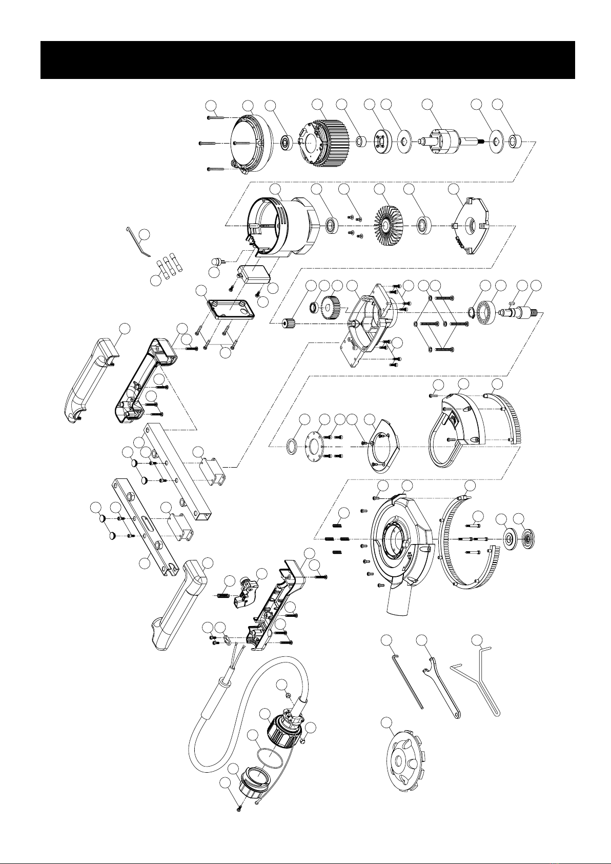
EXPLODED VIEW
06
07
16
15
11
12
12
17
18
19
21
21
13
13
14
14 69
09
42
43
45
47
48
49
50
51
31
35
32
01
30
34
06
57
58
52
59
64
63
62
12
22
23
26
27
29
36
37
38
39
40
41
44
46
45
53
54
55
56
65
66
67
NO.01~69 A1 Version 1.2
20
25
33
60
61
A1
01 02
03
04
05
68
05
17
18
28
28
24
08
10

17
NO. Parts Name Q'ty
1 PANHEAD TAPPING SCREW (M4x12) 5
2 PLUG CAP 1
3 O-RING (AS-137) 1
4 MOTOR COUPLING CABLE SET 1
5 CAP NUT 2
6 PANHEAD TAPPING SCREW (M4x14) 5
7 CABLE CLIP 1
8 HANDLE HALF-RIGHT 1
9 SPRING (Ø1.0 x Ø6.4 x Ø8.4 x 8.5T x 35L) 1
10 SWITCH ACTUATOR (BLACK)(LOCK-ON) 1
11 HANDLE HALF-RIGHT 1
12 PANHEAD TAPPING SCREW (M4x35) 6
13 PANHEAD TAPPING SCREW (M4x20) 5
14 PANHEAD TAPPING SCREW (M4x25) 4
15 HANDLE HALF-LEFT 1
16 HANDLE HALF-LEFT 1
17 RUBBER PLUG 4
18 SOCKET CAP SCREW (M4x6xP0.7) 4
19 CROSS BAR LOWER 1
20 CROSS BAR UPPER 1
21 ANTI-VIBRATION MOUNT 2
22 TAIL COVER 1
23 BALL BEARING (6200-ZZ ) 1
24 STATOR 1
25 SPACER 1
26 MAGNET HOLDER 1
27 ROTOR 1
28 ROTOR END PLATE 2
29 SPACER 1
30 PANHEAD TAPPING SCREW (M4x16) 4
31 ELECTRONICS COVER 1
32 LED INDICATOR LIGHT 1
33 PANHEAD TAPPING SCREW (M4x10) 6
34 ELECTRONICS UNIT 1
35 MOTOR HOUSING 1
PARTS LIST
NO. Parts Name Q'ty
36 BALL BEARING (6002 ) 1
37 TRUSS HEAD TAPPING SCREW M4x8) 4
38 FAN 1
39 BALL BEARING (6202 ) 1
40 GEAR PLATE 1
41 BEVEL PINION GEAR (M1.5x10T) 1
42 BALL BEARING (608) 1
43 OUTPUT GEAR (M1.5x31T) 1
44 GEAR HOUSING 1
45 SOCKET CAP SCREW (M4x12xP0.7) 8
46 SPRING WASHER (M5) 4
47 PANHEAD TAPPING SCREW (M5x40) 4
48 EXTERNAL CIRCLIP (S-17) 1
49 BALL BEARING (6303) 1
50 PARALLEL KEY (5x5x12) 1
51 M14xP2.0-88mm 1
52 OIL SEAL (Ø24xØ32x4) 1
53 BEARING PLATE 1
54 SOCKET CAP SCREW (M4x10xP0.7) 4
55 FLAT HEAD TAPPING SCREW (M4x10) 3
56 COVER PANEL 1
57 HALF-MOON DOOR 1
58 SKIRT BRUSH - SMALL 1
59 SPRING (Ø0.55xØ4.9xØ6x15Lx6T) 4
60 DUST SKIRT 1
61 SKIRT BRUSH - LARGE 1
62 SHOULDER BOLT (M4xP0.7x32L) 4
63 INNER FLANGE (Ø22.2 / Ø25.4) 1
64 OUTER FLANGE (M14) 1
65 SOCKET HEX KEY (M6) 1
66 LOCK NUT WRENCH (30MM) 1
67 FACE SPANNER WRENCH (78MM) 1
68 HEAT SHRINK BUTT CONNECTOR 3
69 ZIP TIE (2.5x100MM) 1
A1 DIAMOND GRINDING HEAD (60/80) 1
18
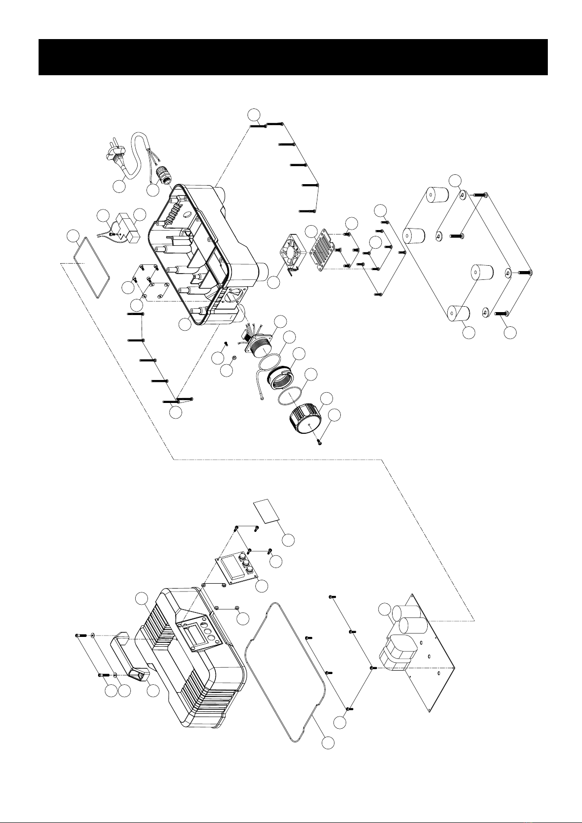
EXPLODED VIEW (Power Converter)
27
26
30
31
33
23
20
32
10
09
06
17
19
20
11
16
03
02
04
15
21
24
25
11
29
28
04
18
22
05
08
07
01
11
14
NO.01~33 Version 1.3
12
13

19
NO. Parts Name Q'ty
1 POWER SUPPLY CABLE 1
2 CABLE GLAND 1
3 HOUSING - LOWER 1
4 SOCKET CAP SCREW (M4-0.7 x 10) 8
5SPRING WASHER (M4) 4
6 MIL-SPEC SOCKET RECEPTACLE 1
7 TETHER 1
8 BAYONET COLLAR 1
9 O-RING (Ø52.07 x 2.62) 1
10 CAP 1
11 PANHEAD TAPPING SCREW (M4 x 12) 6
12 PANHEAD MACHINE SCREW (M5-0.8 x 8) 1
13 NYLOCK NUT (M5-0.8) 1
14 FAN UNIT 1
15 FAN GRILL 1
16 PANHEAD TAPPING SCREW (M5 x 10) 4
17 FOOT 4
18 FLAT WASHER (Ø6.5 x Ø13 x 1) 4
19 PANHEAD SCREW 4
20 PANHEND TAPPING SCREW (5/32" x 1 1/2") 12
21 BRAKING RESISTOR 1
22 MOLDED GASKET (Ø2 x 37cm) 1
23 ELECTRONICS UNIT 1
24 TRUSS HEAD TAPPING SCREW (M4 x 12) 6
25 MOLDED GASKET (Ø2 x 87cm) 1
26 HOUSING - UPPER 1
27 TOP HANDLE 1
28 FLAT WASHER (Ø5 x Ø12 x 1) 2
29 PANHEAD TAPPING SCREW (M5 x 25) 2
30 HEX NUT (M4-0.7) 4
31 LCD DISPLAY 1
32 PANHEAD MACHINE SCREW (M4-0.7 x 12) 4
33 WINDOW (65 x 35 x 1) 1
PARTS LIST (Power Converter)
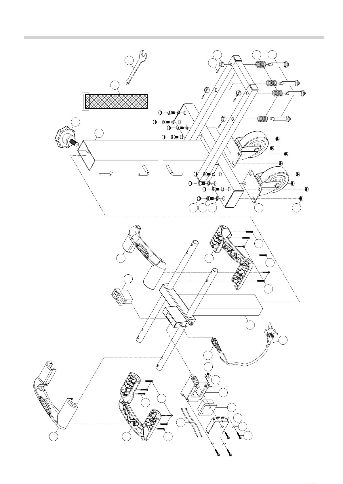
20
FLOOR GRINDING TROLLEY EXPLODED VIEW
NO.01~33 Version 1.3
05
02
01
03
04
25
26
29
30
28
27
09
10
06
07
06
07
05
08
23
24
22
32
33
21
19
18
17
15 14
13
16
20
11
12
This manual suits for next models
1
Table of contents
Other TRAXX Grinder manuals


Popular Grinder manuals by other brands

Inelco
Inelco AutoGrind Digital user manual

Lincoln Electric
Lincoln Electric K5447-1 instruction manual

EWM
EWM TGM 40230 Handy operating instructions

Rikon Power Tools
Rikon Power Tools 80-800VS Operator's manual

EINHELL
EINHELL AXXIO 18/115 operating instructions
 Original operating instructions")
Hilti
Hilti AG 100-8 (S/D) Original operating instructions


Black & Decker
Black & Decker Linea Pro KG915 instruction manual

Trumpf
Trumpf quicksharp Operator's manual

Atlas Copco
Atlas Copco LSF12 S400-2 Original product instructions

Worx
Worx WU736 Original instructions

EINHELL
EINHELL Bavaria BAG 230 Original operating instructions

Scheppach
Scheppach PWS-115 Translation of original instruction manual