TRC Advanced Energy CoolX 600 Series User manual

TRC ELECTRONICS, INC.
Providing exceptional customer service since 1982
C
C
o
o
o
o
l
l
X
X
®
®
6
6
0
0
0
0
M
M
o
o
d
d
u
u
l
l
a
a
r
r
P
P
o
o
w
w
e
e
r
r
S
S
u
u
p
p
p
p
l
l
y
y
Designers Manual
S
S
e
e
p
p
t
t
e
e
m
m
b
b
e
e
r
r
2
2
0
0
1
1
9
9
5
5
7
7
0
0
1
1
0
0
2
2
0
0
8
8
-
-
0
0
0
0
B
B
TRC ELECTRONICS, INC. 1.888.612.9514 www.trcelectronics.com
Designers Manual
Advanced Energy CoolX600 Series

TRC ELECTRONICS, INC.
Providing exceptional customer service since 1982
Table of Contents
C
C
h
h
a
a
p
p
t
t
e
e
r
r
1
1
.
.
S
S
a
a
f
f
e
e
t
t
y
y
a
a
n
n
d
d
P
P
r
r
o
o
d
d
u
u
c
c
t
t
C
C
o
o
m
m
p
p
l
l
i
i
a
a
n
n
c
c
e
e
G
G
u
u
i
i
d
d
e
e
l
l
i
i
n
n
e
e
s
s
Important Safety Information ................................................................................. 1-1
Danger, Warning, and Caution Boxes ................................................................... 1-1
Safety Guidelines .................................................................................................. 1-1
Rules for Safe Installation and Operation ....................................................... 1-2
Interpreting Product Labels ................................................................................... 1-2
Product Compliance .............................................................................................. 1-3
Product Certification ................................................................................ ....... 1-3
Safety Approvals ..................................................................................... ....... 1-3
Low Voltage Directive (LVD) 2006/95/EC ................................................ 1-4
EMC Characteristics ....................................................................................... 1-5
EMC Directive 2004/108/EC ............................................................. ....... 1-5
EMC Criteria ..................................................................................... ....... 1-6
Additional EMI Characterization ............................................................... 1-6
Guidelines for Optimum EMC Performance ............................................. 1-6
Safety and EMC Directives and Standards ............................................. ....... 1-7
Environmental Compliance ............................................................................. 1-7
C
C
h
h
a
a
p
p
t
t
e
e
r
r
2
2
.
.
P
P
r
r
o
o
d
d
u
u
c
c
t
t
O
O
v
v
e
e
r
r
v
v
i
i
e
e
w
w
General Description ....................................................................................... ....... 2-1
CoolPac Options ............................................................................................. 2-1
CoolPac Operation .................................................................................. ....... 2-2
Auxiliary Voltage (Bias) ............................................................................ 2-3
Theory of Operation ....................................................................................... ....... 2-3
C
C
h
h
a
a
p
p
t
t
e
e
r
r
3
3
.
.
S
S
p
p
e
e
c
c
i
i
f
f
i
i
c
c
a
a
t
t
i
i
o
o
n
n
s
s
Physical Specifications .......................................................................................... 3-1
Electrical Specifications ................................................................................. ....... 3-2
Standard Module Specifications .............................................................. ....... 3-4
Bulk Module Specifications ............................................................................. 3-9
Dual Module Specifications ..................................................................... ..... 3-13
Wide-trim Module Specifications ............................................................. ..... 3-16
Environmental Specifications .............................................................................. 3-20
C
C
h
h
a
a
p
p
t
t
e
e
r
r
4
4
.
.
C
C
o
o
n
n
f
f
i
i
g
g
u
u
r
r
a
a
t
t
i
i
o
o
n
n
To Determine an Appropriate Configuration .................................................. ....... 4-1
CoolX Configuration Part Numbers ....................................................................... 4-1
Advanced Energy®CoolX®600 Modular Power Supply
57010208-00B ivTable of Contents
TRC ELECTRONICS, INC. 1.888.612.9514 www.trcelectronics.com
Designers Manual
Advanced Energy CoolX600 Series

TRC ELECTRONICS, INC.
Providing exceptional customer service since 1982
TRC ELECTRONICS, INC. 1.888.612.9514 www.trcelectronics.com
Designers Manual
Advanced Energy CoolX600 Series
To Configure a CoolX Part Number ................................................................ 4-2
Specifying Modules in the Part Number .................................................. ....... 4-3
Selecting and Ordering a Configured CoolX Unit .................................... ....... 4-4
Configuration Example 1 .......................................................................... 4-4
Configuration Example 2 .......................................................................... 4-4
C
C
h
h
a
a
p
p
t
t
e
e
r
r
5
5
.
.
C
C
o
o
m
m
m
m
u
u
n
n
i
i
c
c
a
a
t
t
i
i
o
o
n
n
C
C
o
o
n
n
t
t
r
r
o
o
l
l
s
s
Global Signals ....................................................................................................... 5-1
CoolPac Open Collector Driving Common Logic Levels ......................... ....... 5-1
AC Fail Signal ................................................................................................. 5-2
Global Power Good Signal ...................................................................... ....... 5-3
Global Enable/Inhibit (Control) ................................................................ ....... 5-3
Overtemperature Protection .................................................................... ....... 5-3
Module Signals ...................................................................................................... 5-4
Module Enable/Inhibit .............................................................................. ....... 5-4
Reversing Enable/Inhibit Logic ......................................................... ....... 5-5
Dual Module Enable/Inhibit ............................................................... ....... 5-6
CoolMod Power Good Signal .................................................................. ....... 5-6
Dual Module Power Good Signal ............................................................. 5-7
PMBus Communications ....................................................................................... 5-7
C
C
h
h
a
a
p
p
t
t
e
e
r
r
6
6
.
.
I
I
n
n
s
s
t
t
a
a
l
l
l
l
a
a
t
t
i
i
o
o
n
n
,
,
S
S
e
e
t
t
u
u
p
p
,
,
a
a
n
n
d
d
O
O
p
p
e
e
r
r
a
a
t
t
i
i
o
o
n
n
Preparing to Install the Unit ................................................................................... 6-1
Installation Considerations ...................................................................... ....... 6-1
Mechanical Information ........................................................................... ....... 6-1
Unit Dimensional Drawings ...................................................................... 6-1
IEC Unit Dimensional Drawings ............................................................... 6-3
CoolPac Input Connectors ................................................................ ....... 6-5
Auxiliary Bias Supply Voltage ........................................................... ....... 6-5
CoolMod Output Power and Sense Connectors ............................... ....... 6-6
Dual Module Output Power and Signal Connectors ......................... ....... 6-7
Global System Signal Connector ...................................................... ....... 6-8
DC Output Signals and Control Connectors ..................................... ....... 6-8
Installing the Unit ................................................................................................... 6-9
To Install CoolMod Modules .................................................................... ....... 6-9
Series Connection of Module Outputs .............................................. ....... 6-9
Parallel Connection of CoolMod Outputs ............................................... 6-10
Parallel Connection of Bulk CoolMod Outputs ....................................... 6-12
Mounting the CoolPac ............................................................................. ..... 6-13
First Time Operation ...................................................................................... ..... 6-13
Normal Operation ................................................................................................ 6-14
CoolMod Operation ................................................................................. ..... 6-14
CoolMod Startup and Shutdown ....................................................... ..... 6-14
Power Ratings ........................................................................................ 6-14
Voltage Adjustment ................................................................................ 6-16
Current Limit Adjustment .................................................................. ..... 6-19
Advanced Energy®CoolX®600 Modular Power Supply
57010208-00B vTable of Contents

TRC ELECTRONICS, INC.
Providing exceptional customer service since 1982
TRC ELECTRONICS, INC. 1.888.612.9514 www.trcelectronics.com
Designers Manual
Advanced Energy CoolX600 Series
Overvoltage Protection (OVP) .......................................................... ..... 6-23
Power Limit ....................................................................................... ..... 6-23
Remote Sense .................................................................................. ..... 6-24
Measurement of Ripple and Noise ......................................................... 6-24
Maintenance ........................................................................................................ 6-25
To Remove CoolMod Modules ................................................................ ..... 6-25
Reliability ................................................................................................. ..... 6-25
Calculating MTBF ............................................................................. ..... 6-27
MTBF and Temperature ......................................................................... 6-27
Shelf Life of Power Supplies ............................................................. ..... 6-27
C
C
h
h
a
a
p
p
t
t
e
e
r
r
7
7
.
.
T
T
r
r
o
o
u
u
b
b
l
l
e
e
s
s
h
h
o
o
o
o
t
t
i
i
n
n
g
g
a
a
n
n
d
d
G
G
l
l
o
o
b
b
a
a
l
l
S
S
e
e
r
r
v
v
i
i
c
c
e
e
s
s
Minimizing System Noise ...................................................................................... 7-1
Contact Information ............................................................................................... 7-1
Advanced Energy®CoolX®600 Modular Power Supply
57010208-00B viTable of Contents

TRC ELECTRONICS, INC.
Providing exceptional customer service since 1982
TRC ELECTRONICS, INC. 1.888.612.9514 www.trcelectronics.com
Designers Manual
Advanced Energy CoolX600 Series
List of Tables
Table 1-1. CoolX galvanic isolation barriers .......................................................... 1-3
Table 1-2. CoolPac safety certifications ................................................................ 1-4
Table 1-3. EMC characteristics of CoolX unit under load conditions ............. ....... 1-5
Table 1-4. EMC criteria .................................................................................. ....... 1-6
Table 2-1. CoolPac chassis options ...................................................................... 2-1
Table 2-2. CoolPac options ................................................................................... 2-2
Table 3-1. Physical specifications ......................................................................... 3-1
Table 3-2. Electrical specifications ........................................................................ 3-2
Table 3-3. General standard module outputs ........................................................ 3-4
Table 3-4. Standard module ratings specifications ........................................ ....... 3-4
Table 3-5. Standard module ripple and noise specifications ................................. 3-5
Table 3-6. Standard module regulation specifications ................................... ....... 3-5
Table 3-7. Standard module protective limits specifications .......................... ....... 3-6
Table 3-8. Standard module hiccup characteristics specifications ........................ 3-6
Table 3-9. Standard module transient response specifications ..................... ....... 3-7
Table 3-10. Standard module startup/shutdown timing specifications ........... ....... 3-8
Table 3-11. Standard module enable/disable timing specifications ............... ....... 3-9
Table 3-12. General bulk module outputs ............................................................. 3-9
Table 3-13. Bulk module ratings specifications ................................................... 3-10
Table 3-14. Bulk module ripple and noise specifications ............................... ..... 3-10
Table 3-15. Bulk module regulation specifications .............................................. 3-10
Table 3-16. Bulk module protective limits specifications ..................................... 3-11
Table 3-17. Bulk module hiccup characteristics specifications ...................... ..... 3-11
Table 3-18. Bulk module transient response specifications ........................... ..... 3-12
Table 3-19. Bulk module startup/shutdown timing specifications ........................ 3-12
Table 3-20. Bulk module enable/disable timing specifications ............................ 3-12
Table 3-21. General dual module outputs ........................................................... 3-13
Table 3-22. Dual module ratings specifications ............................................. ..... 3-13
Table 3-23. Dual module ripple and noise specifications .................................... 3-14
Table 3-24. Dual module regulation specifications ........................................ ..... 3-14
Table 3-25. Dual module protective limits specifications ............................... ..... 3-15
Table 3-26. Dual module transient response specifications (25% to 75%
load change) ...................................................................................................... 3-15
Table 3-27. Dual module startup/shutdown timing specifications .................. ..... 3-15
Table 3-28. Dual module enable/disable timing specifications ...................... ..... 3-16
Table 3-29. General wide-trim module outputs .............................................. ..... 3-16
Table 3-30. Wide-trim module ratings specifications ..................................... ..... 3-17
Table 3-31. Wide-trim module ripple and noise specifications ............................ 3-17
Table 3-32. Wide-trim module regulation specifications ................................ ..... 3-18
Table 3-33. Wide-trim module protective limits specifications ....................... ..... 3-18
Table 3-34. Wide-trim module hiccup characteristics specifications ................... 3-19
Table 3-35. Wide-trim module transient response specifications ........................ 3-19
Table 3-36. Wide-trim module startup/shutdown timing specifications .......... ..... 3-20
Table 3-37. Wide-trim module enable/disable timing specifications .............. ..... 3-20
Table 3-38. Environmental standard specifications ....................................... ..... 3-20
Advanced Energy®CoolX®600 Modular Power Supply
57010208-00B viiList of Tables

TRC ELECTRONICS, INC.
Providing exceptional customer service since 1982
TRC ELECTRONICS, INC. 1.888.612.9514 www.trcelectronics.com
Designers Manual
Advanced Energy CoolX600 Series
Table 3-39. Climatic specifications ...................................................................... 3-21
Table 4-1. Part number digit description ........................................................ ....... 4-2
Table 5-1. J1005 system signal connector pin assignments ................................. 5-1
Table 5-2. Table of logics ...................................................................................... 5-2
Table 5-3. Module status with and without a jumper between pins 1 and 2 of
J1011 ................................................................................................................... 5-5
Table 5-4. Dual module enable/inhibit specifications ..................................... ....... 5-6
Table 5-5. Applicable PMBus commands for standard and wide-trim
modules ............................................................................................................... 5-8
Table 5-6. Applicable PMBus commands for bulk modules .................................. 5-9
Table 5-7. Applicable PMBus commands for dual modules ................................ 5-10
Table 5-8. Applicable PMBus commands for chassis .................................... ..... 5-11
Table 6-1. Options for connecting AC mains input to the CoolX unit ............. ....... 6-5
Table 6-2. Output power and sense connector details for all modules .......... ....... 6-7
Table 6-3. Dual module output power and sense connector specifications ... ....... 6-7
Table 6-4. J1005 system signal connector types .................................................. 6-8
Table 6-5. CoolMod signal connector pin assignments ................................. ....... 6-9
Table 6-6. CoolMod output signal connector types ............................................... 6-9
Table 6-7. Standard and wide-trim module parallel voltage tolerances ......... ..... 6-11
Table 6-8. Startup delays for modules ........................................................... ..... 6-14
Table 6-9. K and F values for calculating Vtrim ............................................. ..... 6-17
Table 6-10. K values for calculating Itrim ............................................................ 6-20
Table 7-1. Contact information .............................................................................. 7-2
Advanced Energy®CoolX®600 Modular Power Supply
57010208-00B viiiList of Tables

TRC ELECTRONICS, INC.
Providing exceptional customer service since 1982
TRC ELECTRONICS, INC. 1.888.612.9514 www.trcelectronics.com
Designers Manual
Advanced Energy CoolX600 Series
List of Figures
Figure 2-1. J1 auxiliary output connector .............................................................. 2-3
Figure 2-2. Operational block diagram .................................................................. 2-4
Figure 3-1. Module ripple and noise ...................................................................... 3-5
Figure 3-2. Module hiccup characteristics ............................................................. 3-6
Figure 3-3. Module transient response .......................................................... ....... 3-7
Figure 3-4. Module startup/shutdown timing ......................................................... 3-8
Figure 3-5. Module enable/disable timing ...................................................... ....... 3-8
Figure 4-1. CoolX part number format ........................................................... ....... 4-1
Figure 5-1. J1005 system signal connector ................................................... ....... 5-1
Figure 5-2. CoolMod power good implementation circuit ...................................... 5-2
Figure 5-3. CoolMod enable/inhibit wiring diagram ............................................... 5-4
Figure 5-4. PMBus address header ............................................................... ....... 5-5
Figure 5-5. Dual module enable/inhibit wiring diagram .................................. ....... 5-6
Figure 5-6. Dual module Power Good wiring diagram ................................... ....... 5-7
Figure 6-1. CoolX unit dimensions, DC outputs view ............................................ 6-2
Figure 6-2. CoolX unit dimensions, side view ................................................ ....... 6-2
Figure 6-3. CoolX unit dimensions, AC input view ......................................... ....... 6-2
Figure 6-4. CoolX unit dimensions, bottom view ................................................... 6-3
Figure 6-5. CoolX IEC version unit dimensions, DC outputs view ................. ....... 6-3
Figure 6-6. CoolX IEC version unit dimensions, side view .................................... 6-4
Figure 6-7. CoolX IEC version unit dimensions, AC input view ..................... ....... 6-4
Figure 6-8. CoolX IEC version unit dimensions, top view .............................. ....... 6-4
Figure 6-9. Three screw terminal block ................................................................. 6-5
Figure 6-10. Optional IEC320 inlet terminal .......................................................... 6-5
Figure 6-11. J1 auxiliary output connector ............................................................ 6-6
Figure 6-12. Standard and wide-trim module power terminals and sense
connector ............................................................................................................. 6-6
Figure 6-13. Bulk module power terminals and sense connector .................. ....... 6-6
Figure 6-14. Dual module power terminals and signal connector .................. ....... 6-7
Figure 6-15. CoolMod signal connectors ....................................................... ....... 6-8
Figure 6-16. Modules connected in series with a series connection link ....... ..... 6-10
Figure 6-17. Modules connected in parallel with parallel connection links .......... 6-11
Figure 6-18. Chassis line derating ................................................................. ..... 6-15
Figure 6-19. Chassis and module temperature derating ..................................... 6-15
Figure 6-20. CoolMod wiring diagram for remote voltage setting using
external voltage ............................................................................................ ..... 6-17
Figure 6-21. Vtrim versus Vout ...................................................................... ..... 6-17
Figure 6-22. CoolMod wiring diagram for remote voltage setting using
external resistance ....................................................................................... ..... 6-18
Figure 6-23. Rtrim versus Vout ...................................................................... ..... 6-18
Figure 6-24. Current limit characteristics ....................................................... ..... 6-19
Figure 6-25. CoolMod wiring diagram for remote current setting using
external voltage ............................................................................................ ..... 6-20
Figure 6-26. Itrim versus Iout ......................................................................... ..... 6-21
Advanced Energy®CoolX®600 Modular Power Supply
57010208-00B ixList of Figures

TRC ELECTRONICS, INC.
Providing exceptional customer service since 1982
TRC ELECTRONICS, INC. 1.888.612.9514 www.trcelectronics.com
Designers Manual
Advanced Energy CoolX600 Series
Figure 6-27. CoolMod wiring diagram for remote current setting using
external resistance ....................................................................................... ..... 6-21
Figure 6-28. Rtrim versus Iout ............................................................................. 6-22
Figure 6-29. Foldback current limit circuit ...................................................... ..... 6-22
Figure 6-30. Current and power overload characteristics .............................. ..... 6-23
Figure 6-31. Failure rate of a power supply ................................................... ..... 6-26
Advanced Energy®CoolX®600 Modular Power Supply
57010208-00B xList of Figures
TRC ELECTRONICS, INC.
Providing exceptional customer service since 1982
TRC ELECTRONICS, INC. 1.888.612.9514 www.trcelectronics.com
Designers Manual
Advanced Energy CoolX600 Series
Safety and Product Compliance
Guidelines
I
I
M
M
P
P
O
O
R
R
T
T
A
A
N
N
T
T
S
S
A
A
F
F
E
E
T
T
Y
Y
I
I
N
N
F
F
O
O
R
R
M
M
A
A
T
T
I
I
O
O
N
N
To ensure safe installation and operation of the Advanced Energy CoolX unit, read
and understand this manual before attempting to install and operate this unit. At a
minimum, read and follow the safety guidelines, instructions, and practices.
D
D
A
A
N
N
G
G
E
E
R
R
,
,
W
W
A
A
R
R
N
N
I
I
N
N
G
G
,
,
A
A
N
N
D
D
C
C
A
A
U
U
T
T
I
I
O
O
N
N
B
B
O
O
X
X
E
E
S
S
This symbol represents important notes concerning potential harm to people, this
unit, or associated equipment. Advanced Energy includes this symbol in danger,
warning, and caution boxes to identify specific levels of hazard seriousness.
DANGER:
D
D
A
A
N
N
G
G
E
E
R
R
i
i
n
n
d
d
i
i
c
c
a
a
t
t
e
e
s
s
a
a
n
n
i
i
m
m
m
m
i
i
n
n
e
e
n
n
t
t
l
l
y
y
h
h
a
a
z
z
a
a
r
r
d
d
o
o
u
u
s
s
s
s
i
i
t
t
u
u
a
a
t
t
i
i
o
o
n
n
t
t
h
h
a
a
t
t
,
,
i
i
f
f
n
n
o
o
t
t
a
a
v
v
o
o
i
i
d
d
e
e
d
d
,
,
w
w
i
i
l
l
l
l
r
r
e
e
s
s
u
u
l
l
t
t
i
i
n
n
d
d
e
e
a
a
t
t
h
h
o
o
r
r
s
s
e
e
r
r
i
i
o
o
u
u
s
s
i
i
n
n
j
j
u
u
r
r
y
y
.
.
D
D
A
A
N
N
G
G
E
E
R
R
i
i
s
s
l
l
i
i
m
m
i
i
t
t
e
e
d
d
t
t
o
o
t
t
h
h
e
e
m
m
o
o
s
s
t
t
e
e
x
x
t
t
r
r
e
e
m
m
e
e
s
s
i
i
t
t
u
u
a
a
t
t
i
i
o
o
n
n
s
s
.
.
WARNING:
W
W
A
A
R
R
N
N
I
I
N
N
G
G
i
i
n
n
d
d
i
i
c
c
a
a
t
t
e
e
s
s
a
a
p
p
o
o
t
t
e
e
n
n
t
t
i
i
a
a
l
l
l
l
y
y
h
h
a
a
z
z
a
a
r
r
d
d
o
o
u
u
s
s
s
s
i
i
t
t
u
u
a
a
t
t
i
i
o
o
n
n
t
t
h
h
a
a
t
t
,
,
i
i
f
f
n
n
o
o
t
t
a
a
v
v
o
o
i
i
d
d
e
e
d
d
,
,
c
c
o
o
u
u
l
l
d
d
r
r
e
e
s
s
u
u
l
l
t
t
i
i
n
n
d
d
e
e
a
a
t
t
h
h
o
o
r
r
s
s
e
e
r
r
i
i
o
o
u
u
s
s
i
i
n
n
j
j
u
u
r
r
y
y
,
,
a
a
n
n
d
d
/
/
o
o
r
r
p
p
r
r
o
o
p
p
e
e
r
r
t
t
y
y
d
d
a
a
m
m
a
a
g
g
e
e
.
.
CAUTION:
C
C
A
A
U
U
T
T
I
I
O
O
N
N
i
i
n
n
d
d
i
i
c
c
a
a
t
t
e
e
s
s
a
a
p
p
o
o
t
t
e
e
n
n
t
t
i
i
a
a
l
l
l
l
y
y
h
h
a
a
z
z
a
a
r
r
d
d
o
o
u
u
s
s
s
s
i
i
t
t
u
u
a
a
t
t
i
i
o
o
n
n
t
t
h
h
a
a
t
t
,
,
i
i
f
f
n
n
o
o
t
t
a
a
v
v
o
o
i
i
d
d
e
e
d
d
,
,
c
c
o
o
u
u
l
l
d
d
r
r
e
e
s
s
u
u
l
l
t
t
i
i
n
n
m
m
i
i
n
n
o
o
r
r
o
o
r
r
m
m
o
o
d
d
e
e
r
r
a
a
t
t
e
e
i
i
n
n
j
j
u
u
r
r
y
y
,
,
a
a
n
n
d
d
/
/
o
o
r
r
p
p
r
r
o
o
p
p
e
e
r
r
t
t
y
y
d
d
a
a
m
m
a
a
g
g
e
e
.
.
C
C
A
A
U
U
T
T
I
I
O
O
N
N
i
i
s
s
a
a
l
l
s
s
o
o
u
u
s
s
e
e
d
d
f
f
o
o
r
r
p
p
r
r
o
o
p
p
e
e
r
r
t
t
y
y
-
-
d
d
a
a
m
m
a
a
g
g
e
e
-
-
o
o
n
n
l
l
y
y
a
a
c
c
c
c
i
i
d
d
e
e
n
n
t
t
s
s
.
.
S
S
A
A
F
F
E
E
T
T
Y
Y
G
G
U
U
I
I
D
D
E
E
L
L
I
I
N
N
E
E
S
S
Review the following information before attempting to install and operate the
product.
CoolX®600 Modular Power Supply Chapter
1
1
57010208-00B Safety and Product Compliance Guidelines 1‑1

TRC ELECTRONICS, INC.
Providing exceptional customer service since 1982
TRC ELECTRONICS, INC. 1.888.612.9514 www.trcelectronics.com
Designers Manual
Advanced Energy CoolX600 Series
Rules for Safe Installation and Operation
Please note the following rules:
• Install the CoolX unit indoors. The CoolX unit is designed for indoor use.
• Install the CoolX unit so that it is only accessible to service engineers.
• Do not unplug CoolMod modules while input power is applied to the CoolPac
chassis. The modules are not designed for hot-plug insertion.
• Ensure that input and output screw terminals are torqued to 2 Nm (17.7 in-lb)
before applying power to the CoolX unit.
• Arrange positive and negative power cables as a twisted pair to minimize
inductive loops.
• Wait 4 minutes after shutting off power before inserting or removing modules.
• Use properly sized wires to avoid overheating and excessive voltage drop.
• Take appropriate precautions when touching the CoolX unit after it has been
operating for a period of time. Due to the conduction cooling methods to the
chassis, the chassis will remain hot for some time after power has been
removed. Exactly how long the chassis remains hot depends on the system
incorporating the CoolX unit.
• Completely disconnect the installation from power before working on the unit.
The unit uses double pole/neutral fusing. If the unit is not completely
disconnected from power, parts might remain live even if one of the two mains
fuses has blown.
I
I
N
N
T
T
E
E
R
R
P
P
R
R
E
E
T
T
I
I
N
N
G
G
P
P
R
R
O
O
D
D
U
U
C
C
T
T
L
L
A
A
B
B
E
E
L
L
S
S
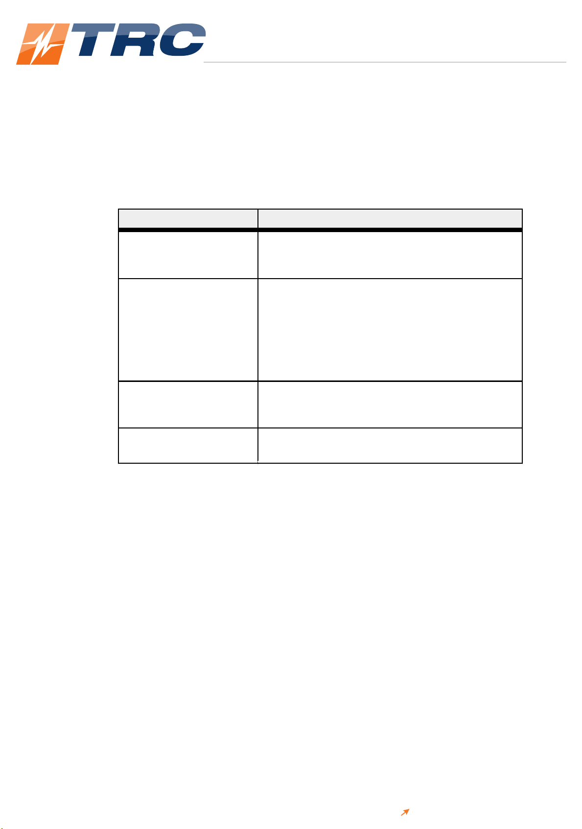
The following labels might appear on your unit:
or
CE label
Complies with applicable European
directives.
Hazardous voltage
Voltage > 30 VRMS, 42.4 V peak, or
60 VDC
Hot surface
Advanced Energy®CoolX®600 Modular Power Supply
57010208-00B Safety and Product Compliance Guidelines 1‑2

TRC ELECTRONICS, INC.
Providing exceptional customer service since 1982
TRC ELECTRONICS, INC. 1.888.612.9514 www.trcelectronics.com
Designers Manual
Advanced Energy CoolX600 Series
Refer to manual for more information
P
P
R
R
O
O
D
D
U
U
C
C
T
T
C
C
O
O
M
M
P
P
L
L
I
I
A
A
N
N
C
C
E
E
The following sections include information about unit compliance and certification,
including the conditions of use required to be in compliance with the standards and
directives.
Product Certification
Certain options of this product may be certified according to the list below.
For more information, refer to the Certificate or Letter of Conformity (US) or
Declaration of Conformity (EU) accompanying the product.
•NRTL – Safety certified by TÜV Rheinland®, a Nationally Recognized Testing
Laboratory
• CE Marking – Self-declaration, assessed by AE Corporate Compliance
• EMC measurements – Verified by AE Corporate Compliance
•SEMI®guidelines – Verified by AE Corporate Compliance
Safety Approvals
CoolX units are compliant with the latest safety approvals and with several future
changes in safety standards for medical, industrial and ITE equipment.
CX06S is certified to IEC60950-1 2nd Edition and is compliant with the upcoming
EN62368-1 safety approvals.
CX06M is certified to IEC60601-1 3rd Edition for medical applications.
Galvanic isolation levels follow:
T
T
a
a
b
b
l
l
e
e
1
1
‑
‑
1
1
.
.
CoolX galvanic isolation barriers
I
I
s
s
o
o
l
l
a
a
t
t
i
i
o
o
n
n
B
B
a
a
r
r
r
r
i
i
e
e
r
r
T
T
y
y
p
p
e
e
W
W
i
i
t
t
h
h
s
s
t
t
a
a
n
n
d
d
V
V
o
o
l
l
t
t
a
a
g
g
e
e
Input to output Reinforced (2 x MOPP) 4000 VAC
Input to case (GND) Basic (1 x MOPP) 1850 VAC
Output to case (GND) Basic (1 x MOPP) 1850 VAC
Advanced Energy®CoolX®600 Modular Power Supply
57010208-00B Safety and Product Compliance Guidelines 1‑3

TRC ELECTRONICS, INC.
Providing exceptional customer service since 1982
TRC ELECTRONICS, INC. 1.888.612.9514 www.trcelectronics.com
Designers Manual
Advanced Energy CoolX600 Series
T
T
a
a
b
b
l
l
e
e
1
1
‑
‑
1
1
.
.
CoolX galvanic isolation barriers (Continued)
I
I
s
s
o
o
l
l
a
a
t
t
i
i
o
o
n
n
B
B
a
a
r
r
r
r
i
i
e
e
r
r
T
T
y
y
p
p
e
e
W
W
i
i
t
t
h
h
s
s
t
t
a
a
n
n
d
d
V
V
o
o
l
l
t
t
a
a
g
g
e
e
Output to output (one
module to another)
Basic (1 x MOPP) 1850 VAC
Output to output (within a
dual module)
Functional 500 VDC
L
L
O
O
W
W
V
V
O
O
L
L
T
T
A
A
G
G
E
E
D
D
I
I
R
R
E
E
C
C
T
T
I
I
V
V
E
E
(
(
L
L
V
V
D
D
)
)
2
2
0
0
0
0
6
6
/
/
9
9
5
5
/
/
E
E
C
C
The LVD applies to equipment with an AC input voltage from 50 V to 1000 V or a
DC input voltage from 75 V to 1500 V. The CoolX series is CE marked to show
compliance with the LVD.
The relevant European standard for the CX06S model is EN 60950-1 2nd Edition
(information technology) and 62368-1 Edition 2. The relevant European standard for
the CS06M model is EN60601-1 3rd Edition (Medical Devices Directive).
The full table of safety certifications follows.
T
T
a
a
b
b
l
l
e
e
1
1
‑
‑
2
2
.
.
CoolPac safety certifications
C
C
o
o
o
o
l
l
P
P
a
a
c
c
C
C
h
h
a
a
s
s
s
s
i
i
s
s
S
S
a
a
f
f
e
e
t
t
y
y
S
S
t
t
a
a
n
n
d
d
a
a
r
r
d
d
s
s
A
A
d
d
d
d
i
i
t
t
i
i
o
o
n
n
a
a
l
l
D
D
e
e
t
t
a
a
i
i
l
l
s
s
CX06S IEC/EN 60950-1 Edition 2
and all national deviations
UL 60950-1/CSA C22.2
No 60950-1 Edition 2
5000 m (16,404′) altitude,
100 VAC to 240 VAC ±
10%
IEC 62368-1 Edition 2 IEC 62368-1 (2014)
Edition 2
5000 m (16,404′) altitude,
100 VAC to 240 VAC ±
10%
CX06M IEC/EN 60601-1 Edition 3
and all national deviations
IEC 60601-1(2005), EN
60601-1(2006) ANSI/
AAMI ES 60601-1(2005)
CAN/CSA C22.2 No.
60601-1 (2008)
5000 m (16,404′) altitude,
100 VAC to 240 VAC ±
10%
Advanced Energy®CoolX®600 Modular Power Supply
57010208-00B Safety and Product Compliance Guidelines 1‑4

TRC ELECTRONICS, INC.
Providing exceptional customer service since 1982
TRC ELECTRONICS, INC. 1.888.612.9514 www.trcelectronics.com
Designers Manual
Advanced Energy CoolX600 Series
EMC Characteristics
E
E
M
M
C
C
D
D
I
I
R
R
E
E
C
C
T
T
I
I
V
V
E
E
2
2
0
0
0
0
4
4
/
/
1
1
0
0
8
8
/
/
E
E
C
C
Component power supplies such as the CoolX series are not covered by the EMC
directive. It is not possible for any power supply manufacturer to guarantee
conformity of the final product to the EMC directive, because performance is
critically dependent on the final system configuration. System compliance with the
EMC directive is facilitated by this product complying with several of the
requirements as shown in Table 1‑3. Although CoolX units meet these requirements,
the CE mark does not cover this area.
A full EN60601-1-2 4th Edition test report is available on request. Contact AE Global
Services for details.
T
T
a
a
b
b
l
l
e
e
1
1
‑
‑
3
3
.
.
EMC characteristics of CoolX unit under load conditions
P
P
a
a
r
r
a
a
m
m
e
e
t
t
e
e
r
r
C
C
o
o
n
n
d
d
i
i
t
t
i
i
o
o
n
n
s
s
/
/
D
D
e
e
s
s
c
c
r
r
i
i
p
p
t
t
i
i
o
o
n
n
s
s
C
C
r
r
i
i
t
t
e
e
r
r
i
i
a
a
Radiated emissions EN55011, EN55022 and
FCC, Class B [1]
Conducted emissions EN55011, EN55022 and
FCC, Class B
Power line harmonics EN61000-3-2, Class A
Voltage flicker EN61000-3-3
ESD EN61000-4-2, Level 4,
8 kV contact, 15 kV air
A
Radiated immunity EN61000-4-3, Level 3,
10 V/m
A
Electrical fast transient EN61000-4-4, Level 4, ±
4 kV
A
Surge immunity EN61000-4-5, Level 4,
2 kV DM, 4 kV CM
B
Conducted RF immunity EN61000-4-6, Level 2,
3 VRMS
A
Power frequency magnetic
field
EN61000-4-8, Level 4,
30 A/m
A
1Some applications might require an external ferrite on cabling to meet Class B radiated
EMI. Contact AE Global Services for details.
Radiated EMI should be tested in a system environment. Radiated EMI performance
in a system will vary significantly from a standalone power supply because the
system enclosure provides additional shielding.
Advanced Energy®CoolX®600 Modular Power Supply
57010208-00B Safety and Product Compliance Guidelines 1‑5
TRC ELECTRONICS, INC.
Providing exceptional customer service since 1982
TRC ELECTRONICS, INC. 1.888.612.9514 www.trcelectronics.com
Designers Manual
Advanced Energy CoolX600 Series
E
E
M
M
C
C
C
C
R
R
I
I
T
T
E
E
R
R
I
I
A
A
There are four criteria levels, each referring to a specific performance level of the
product during and after the EMC phenomenon is applied. These are specifically
observed during immunity testing and are described in the following table:
T
T
a
a
b
b
l
l
e
e
1
1
‑
‑
4
4
.
.
EMC criteria
C
C
r
r
i
i
t
t
e
e
r
r
i
i
a
a
L
L
e
e
v
v
e
e
l
l
D
D
e
e
s
s
c
c
r
r
i
i
p
p
t
t
i
i
o
o
n
n
A The apparatus shall continue to operate as intended.
No degradation of performance or loss of function is
observed during or after the test.
B The apparatus shall continue to operate as intended
after the test. No degradation of performance or loss
of function is allowed below a performance level
specified by the manufacturer when the apparatus is
used as intended. During the test, temporary
degradation of performance is allowed if it is self
recoverable.
C Temporary loss of function is allowed during and after
the test that requires operator intervention to restore
the product/apparatus to normal operation.
D During the test, loss of function that is not recoverable
occurs.
A
A
D
D
D
D
I
I
T
T
I
I
O
O
N
N
A
A
L
L
E
E
M
M
I
I
C
C
H
H
A
A
R
R
A
A
C
C
T
T
E
E
R
R
I
I
Z
Z
A
A
T
T
I
I
O
O
N
N
CoolX units are compliant with SEMI F47 for voltage dips and interruptions. Input
voltage must be > 180 VAC.
Contact Advanced Energy Global Services for additional details.
G
G
U
U
I
I
D
D
E
E
L
L
I
I
N
N
E
E
S
S
F
F
O
O
R
R
O
O
P
P
T
T
I
I
M
M
U
U
M
M
E
E
M
M
C
C
P
P
E
E
R
R
F
F
O
O
R
R
M
M
A
A
N
N
C
C
E
E
All CoolX products are designed to comply with European Normative limits (EN) for
conducted and radiated emissions and immunity when correctly installed in a system.
For performance levels attained, refer to Table 1‑3. However, power supply
compliance with these limits is not a guarantee of system compliance. System EMC
performance can be impacted by various system characteristics. Design
considerations, such as PCB layout and tracking, cabling arrangements, and
orientation of the power supply, among others, all directly contribute to the EMC
performance of a system.
Cabling arrangements and PCB tracking layouts are the greatest contributing factors
to system EMC performance. It is important that PCB tracks and power cables are
arranged to minimize current carrying loops that can radiate, and to minimize loops
Advanced Energy®CoolX®600 Modular Power Supply
57010208-00B Safety and Product Compliance Guidelines 1‑6

TRC ELECTRONICS, INC.
Providing exceptional customer service since 1982
TRC ELECTRONICS, INC. 1.888.612.9514 www.trcelectronics.com
Designers Manual
Advanced Energy CoolX600 Series
that could have noise currents induced into them. All cables and PCB tracks should
be treated as radiation sources and antenna, and every effort should be made to
minimize their interaction.
Use the following guidelines to optimize CoolX EMC performance:
• Keep all cable lengths as short as possible.
• Use twisted pairs of power cables, with the maximum possible twist, to
minimize the area of power carrying loops. This will minimize radiation.
• Run PCB power tracks back to back.
• Use twisted pairs for sense cables, with the maximum possible twist, to
minimize noise current induced in signal carrying lines.
• Do not combine power and sense cables in the same harness.
• Ensure good system grounding. System earth should be a starpoint. The power
supply earth should be directly connected to the starpoint. All other earths
should be directed to the starpoint as soon as possible.
Safety and EMC Directives and Standards
For information concerning compliance to applicable EU requirements, refer to the
EU Declaration of Conformity for this unit. The Declaration of Conformity might
also include a supplementary section covering compliance to non-EU regulatory
requirements and/or industry standards or guidelines.
Environmental Compliance
•EU RoHS – European Union Directive 2011/65/EU (RoHS 2)
Restriction of the Use of Certain Hazardous Substances in Electrical and
Electronic Equipment
This product is EU 2011/65/EU (RoHS 2) compliant, containing no more than
the maximum concentration of hazardous substances listed in Annex II, but
might utilize application exemptions in Annex III or IV.
European Delegated Directive (EU) 2015/863 – Amendment to Annex II of
Directive 2011/65/EU (RoHS 2) Regarding the List of Restricted Substances
This product is also compliant to the 2015/863 amendment, containing no more
than the maximum concentration of four additional hazardous substances
(phthalates) listed in amended Annex II.
•EU REACH – European Union Regulation (EC) No. 1907/2006
Registration, Evaluation, Authorization and Restriction of Chemicals
Advanced Energy manufactures articles subject to Article 33 of REACH and,
upon request, will provide information regarding Substances of Very High
Concern (SVHC) currently identified by the European Chemical Agency
Advanced Energy®CoolX®600 Modular Power Supply
57010208-00B Safety and Product Compliance Guidelines 1‑7

TRC ELECTRONICS, INC.
Providing exceptional customer service since 1982
TRC ELECTRONICS, INC. 1.888.612.9514 www.trcelectronics.com
Designers Manual
Advanced Energy CoolX600 Series
(ECHA) that are contained in this product, at concentrations greater than 0.1%
by weight.
Advanced Energy®CoolX®600 Modular Power Supply
57010208-00B Safety and Product Compliance Guidelines 1‑8

TRC ELECTRONICS, INC.
Providing exceptional customer service since 1982
TRC ELECTRONICS, INC. 1.888.612.9514 www.trcelectronics.com
Designers Manual
Advanced Energy CoolX600 Series
Product Overview
G
G
E
E
N
N
E
E
R
R
A
A
L
L
D
D
E
E
S
S
C
C
R
R
I
I
P
P
T
T
I
I
O
O
N
N
The CoolX600 unit is a convection-cooled modular power supply that can provide
600 W with no fan. With an optimum configuration, a CoolX unit can achieve an
efficiency of up to 93%.
The series comprises two base models: the CX06S for industrial applications and the
CX06M for medical applications. A complete power supply consists of a CoolPac
chassis populated with up to four CoolMod modules. Each module provides one or
two isolated DC outputs, and outputs can range from 1 V to 58 V. Each module
output voltage can be individually trimmed to its required setpoint.
You can connect modules in parallel to increase output current, or in series to
increase output voltage (subject to staying within isolation ratings and giving due
consideration to any SELV requirements). You can connect CoolPac chassis in
parallel for higher power and N+1 redundancy applications. For more information,
contact AE Global Services.
A signal interface on each module provides control and output sequencing capability
and status indicators. Alternatively, digital control and monitoring is accessible
through the PMBus®interface.
CoolPac Options
A CoolX unit has two CoolPac chassis options. The following table describes the two
options:
T
T
a
a
b
b
l
l
e
e
2
2
‑
‑
1
1
.
.
CoolPac chassis options
C
C
h
h
a
a
s
s
s
s
i
i
s
s
N
N
u
u
m
m
b
b
e
e
r
r
o
o
f
f
S
S
l
l
o
o
t
t
s
s
P
P
o
o
w
w
e
e
r
r
(
(
W
W
)
)
A
A
p
p
p
p
r
r
o
o
v
v
a
a
l
l
T
T
y
y
p
p
e
e
CX06S 4 600 Industrial Approval IEC 60950-1
2nd Edition and IEC 62368-1 2nd
Edition
CX06M 4 600 Medical Approval IEC 60601-1 3rd
Edition and IEC 60601-1-2 4th
Edition (EMC)
The standard CoolPac chassis has the following features:
• AC mains connector or 3-screw terminal block
CoolX®600 Modular Power Supply Chapter
2
2
57010208-00B Product Overview 2‑1

TRC ELECTRONICS, INC.
Providing exceptional customer service since 1982
TRC ELECTRONICS, INC. 1.888.612.9514 www.trcelectronics.com
Designers Manual
Advanced Energy CoolX600 Series
• Earth leakage current of < 300 μA
The following table describes alternate CoolPac options:
T
T
a
a
b
b
l
l
e
e
2
2
‑
‑
2
2
.
.
CoolPac options
O
O
p
p
t
t
i
i
o
o
n
n
D
D
e
e
s
s
c
c
r
r
i
i
p
p
t
t
i
i
o
o
n
n
Option 1: Input connector The AC mains connector is an IEC320
inlet.
Option 4: Low leakage current 150 μA The leakage current is < 150 μA, meant for
medical applications using two or more
power supplies or containing additional
parts that contribute to the system earth
leakage current. This ensures that system
earth leakage current does not exceed
levels defined in IEC60601 3rd Edition.
Option A: 12 V auxiliary voltage The chassis includes a 12 V/1.97 A
isolated bias supply voltage.
Option B: 5 V auxiliary voltage The chassis includes a 5 V/4.7 A isolated
bias supply voltage.
Option C: Conformal coating The CoolPac chassis has a conformal
coating for harsh environments and MIL-
COTS applications.
Option L: Enclosed frame This chassis has an enclosed frame with a
lid.
CoolPac Operation
The CoolPac chassis provides the front end input power to each module. The
CoolPac chassis operates off 85 VAC to 264 VAC, 47 Hz to 63 Hz and can withstand
300 VAC input voltage for up to 5 sec. The chassis can operate off up to 440 Hz, but
operating off > 63 Hz puts the unit outside the unit safety ratings and approvals.
Contact AE Global Services before operating the unit off > 63 Hz.
The chassis can also operate off DC inputs of 125 VDC to 300 VDC. However,
operation with DC inputs is not within unit safety ratings and approvals. Contact
AE Global Services before operating the unit with DC inputs.
Table 2‑1details each CoolPac version.
Advanced Energy®CoolX®600 Modular Power Supply
57010208-00B Product Overview 2‑2
TRC ELECTRONICS, INC.
Providing exceptional customer service since 1982
TRC ELECTRONICS, INC. 1.888.612.9514 www.trcelectronics.com
Designers Manual
Advanced Energy CoolX600 Series
A
A
U
U
X
X
I
I
L
L
I
I
A
A
R
R
Y
Y
V
V
O
O
L
L
T
T
A
A
G
G
E
E
(
(
B
B
I
I
A
A
S
S
)
)
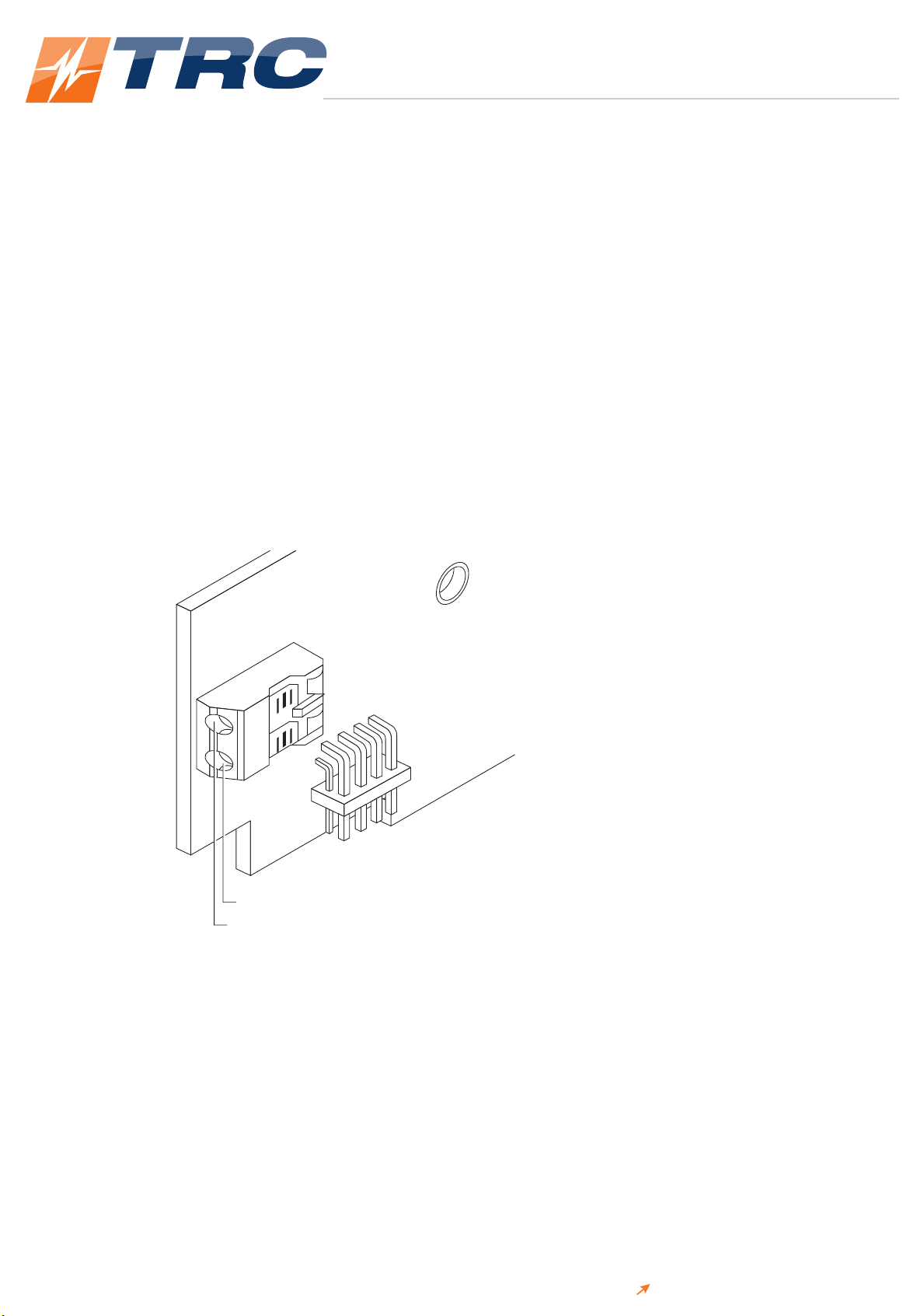
Each CoolPac has an isolated, SELV 24 W auxiliary (always on) voltage of 12 V/
1.97 A or 5 V/4.7 A (optional). This bias supply is available through the J1 connector
and can be used as follows:
• For powering displays
• For system housekeeping
• In control circuits
• As an additional output voltage
☞ Important
The negative of the auxiliary (−Vo) is connected to the common of the system
signal connector.
J1
AUXILIARY
-
V
o
(common)
AUXILIARY +V
o
F
F
i
i
g
g
u
u
r
r
e
e
2
2
‑
‑
1
1
.
.
J1 auxiliary output connector
Refer to “Communication Controls” on page 5‑1 for more details.
T
T
H
H
E
E
O
O
R
R
Y
Y
O
O
F
F
O
O
P
P
E
E
R
R
A
A
T
T
I
I
O
O
N
N
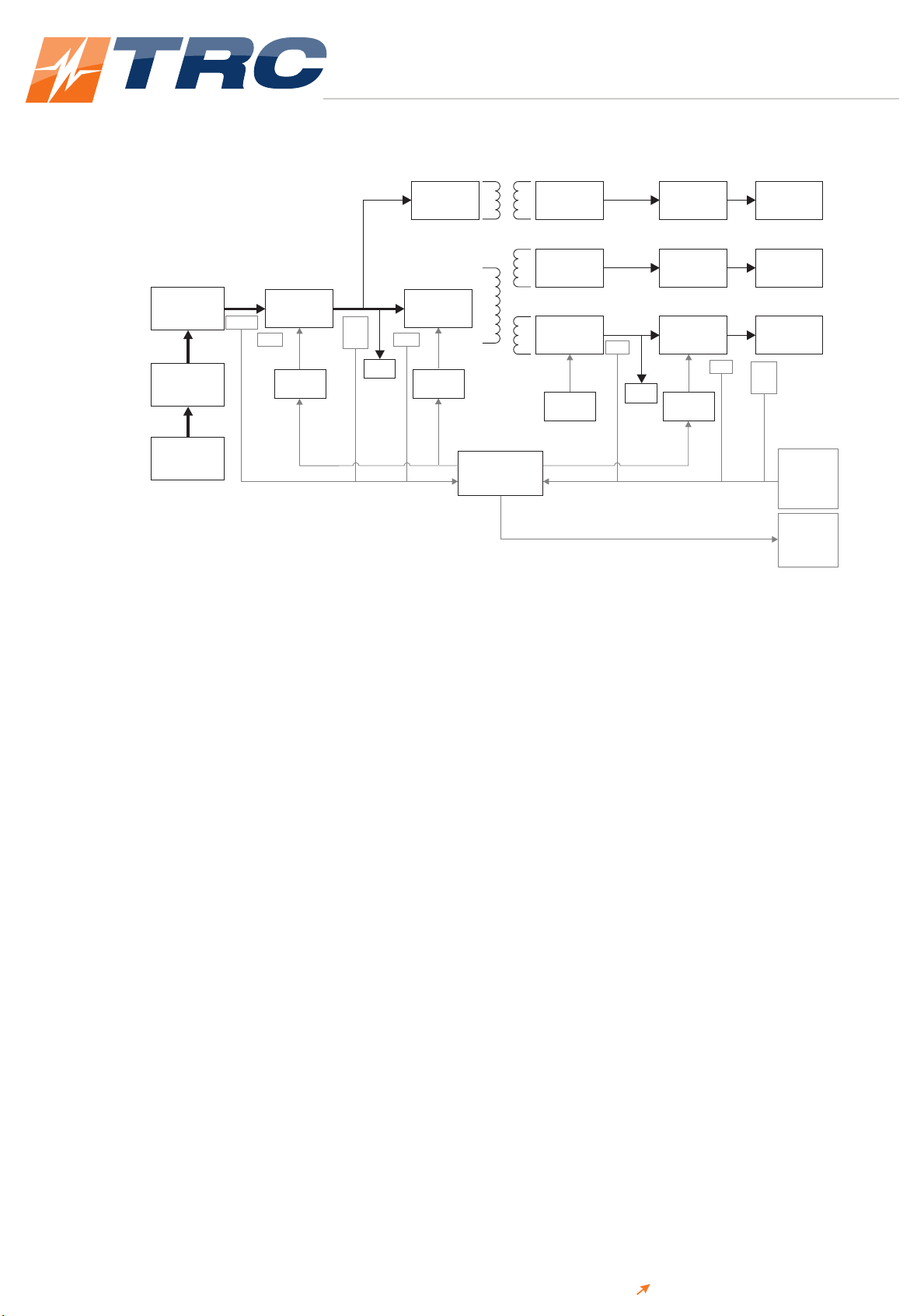
The CoolX platform comprises a CoolPac chassis and CoolMod DC output modules,
all selected to deliver the volts and amps required by the system designer. An
operational block diagram follows:
Advanced Energy®CoolX®600 Modular Power Supply
57010208-00B Product Overview 2‑3
TRC ELECTRONICS, INC.
Providing exceptional customer service since 1982
TRC ELECTRONICS, INC. 1.888.612.9514 www.trcelectronics.com
Designers Manual
Advanced Energy CoolX600 Series
Flyback
converter
Resonant
LLC
Interleaved
PFC
Rectifier and
inrush current
limiting
EMI filter
Dual fused
input
Rectifier
Synchronous
buck
Auxiliary
Out
Vout
Vout
Synchronous
buck
Synchronous
rectifier
Synchronous
rectifier
Communications
board
Synchronous
buck
Buck
controller
Bias
Bias
AC fail
OTP OTP UVP
OTP
OCP
OVP
UVP
Synch
controller
Enable/
disable
V
trim
I
trim
AC fail
OTP alarm
Power good
PMBus
LLC
controller
PFC
controller
OCP
OVP
UVP
F
F
i
i
g
g
u
u
r
r
e
e
2
2
‑
‑
2
2
.
.
Operational block diagram
The chassis is an open-frame chassis containing circuitry for an offline, single-phase,
AC front end; an EMI filter; and a customer interface and associated housekeeping
circuits. Input AC mains voltage (L, N, and GND) is applied to either a screw
terminal input block or an IEC type input connector (optional), and then through an
EMI filter designed to meet EN55022 Class B. Some applications might require an
external ferrite on cabling to meet Class B radiated EMI. Contact AE Global Services
for recommendations.
For medical applications, the EMI filter also ensures that the power supply meets the
low earth leakage current requirements of EN60601-1 3rd Edition. All modules
provide medical isolation of 4000 VAC (2 x MOPP) from input to output and
extended isolation of 1850 VAC from output to earth.
☞ Important
1 x MOPP requirement is 1500 VAC.
A 24 W auxiliary, always-on, isolated bias supply of 12 VDC or 5 VDC (optional) is
provided for peripheral use. This bias supply also has medical isolation of 4000 VAC
(2 x MOPP). A suite of monitoring and controls are provided. Refer to
“Communication Controls” on page 5‑1 for more details.
Modules provide isolated DC outputs. These can be set to the required voltage
setpoints by the user or factory as required. Each module has its own discrete
controls. Refer to “Communication Controls” on page 5‑1 for more details.
To see the galvanic isolation barriers for a configured CoolX unit, refer to Table 1‑1.
Advanced Energy®CoolX®600 Modular Power Supply
57010208-00B Product Overview 2‑4
This manual suits for next models
3
Table of contents


