TSL Tally Man PSU-22 User manual

UMD PSU-22 1 V4.0
The TSL Tally and
UMD Configuring Program
Power Supply PSU-22
– this section is intended to be read in conjunction with the
Introduction
Television Systems Limited.
Vanwall Road, Maidenhead, Berkshire, SL6 4UB
Telephone +44 (0)1628 676200, FAX +44 (0)1628 676299
UMD PSU-22 2 V4.0
Safety
Installation.
Unless otherwise stated TSL equipment may be installed at any angle or position within an operating
temperature range of 5°~ 25°C .
The RJ45 connectors are for use only with TSL UMD equipment.
All TSL equipment conforms to the EC Low Voltage Directive:
EC Low Voltage Directive (73/23/EEC)(OJ L76 26.3.73)(LVD).
Amendment: (93/68/EEC) (OJ L220 30.8.93).
Earthing/Grounding
In all cases, the frame of the equipment must be earthed on installation. Connection to an earthed strip
running the length of the frame is ideal.
The earth pin on the IEC mains inlet connector is connected to the metal frame of the equipment, to 0
volts on the internal DC PSU and to signal ground, unless otherwise stated. All metal panels are
bonded together. Rack mounted equipment must be earthed (grounded).
Mounting
Careful consideration of the of equipment location and mounting in racks must be made. In particular,
consideration must be given to the stability of free-standing racks by mounting heavy equipment low in
the rack. The rear of the unit should be supported in the rack.
Power
For pluggable equipment, the socket outlet shall be installed near the equipment and shall be easily
accessible.
Consideration must be given to the supply circuit loading and switch on/fault surges that will affect
overcurrent protection trips and switches etc.
Check that the fuse rating is correct for the local power (mains) supply. Replacement fuses must be of
the same rating and type for continued protection against fire risk.
The equipment rating is shown on the rear panel.
No power supply cord is provided with this equipment.
Do not switch on until all connections are made.
Ventilation
Due consideration for cooling requirements must be given when mounting the equipment. Ideally 1RU
of rack space should be left above and below the unit.
If the equipment is installed in a closed unit, consideration must be given to providing forced air cooling
in order that the maximum recommended temperature is not exceeded.

UMD PSU-22 3 V4.0
Warranty, Maintenance And Repair
All TSL equipment is guaranteed for one year from the date of delivery to the customer’s premises. If
the equipment is to be stored for a significant period, please contact TSL concerning a possible
extended warranty period.
Failure during warranty
If this TSL product should fail or become faulty within the warranty period, first please check the IEC
inlet fuses.
All maintenance work must be carried out by trained and competent personnel.
If equipment has to be returned to TSL for repair please observe the following overleaf:
TSL Returns Procedure
Please telephone +44 (0)1628 687200 (Fax: +44 (0)1682 687299) and ask for Sales who will provide
a Returns Number. This will enable us to track the unit effectively and will provide some information
prior to the unit arriving.
For each item, this unique Returns Number must be included with the Fault Report sent with the unit.
A contact name and telephone number are also required with the Fault Report sent with the unit.
Fault report details required.
•Company:
•Name:
•Address:
•Contact Name:
•Telephone No:
•Returns Number:
•Symptoms of the fault (to include switch setting positions, input signals etc):
Packing
Please ensure that the unit is well packed as all mechanical damage is chargeable. TSL recommends
that you insure your equipment for transit damage.
The original packaging, when available, should always be used when returning equipment.
If returned equipment is received in a damaged condition, the damage should be reported both
to TSL and the carrier immediately.
Year 2000 Conformity Requirements
This product conforms to the following rules:
Rule 1 No value for the current date will cause any interruption in operation.
Rule 2 Date based functionality will behave consistently for dates prior to, during and after the
Year 2000.
Rule 3 In all interfaces and data storage, the century in any date is specified either explicitly or
by unambiguous algorithms or by inferencing rules.
Rule 4 The Year 2000 is recognised as a leap year.
UMD PSU-22 4 V4.0
EC DECLARATION OF CONFORMITY
Application of Council Directives Nos:
EC Low Voltage Directive (73/23/EEC)(OJ L76 26.3.73)(LVD).
Amendment: (93/68/EEC) (OJ L220 30.8.93).
Conformity Standards Declared:
BS EN60950
EMC Directive: 89/336/EEC, Amended 92/31/EEC.
Conformity Standards Declared:
EN 50081-1, EN 50082-1
Manufacturer’s Name: Television Systems Ltd
Manufacturer’s Address: Vanwall Rd
Maidenhead
Berks SL6 4UB
Type of Equipment: Under Monitor Display Power Supply Unit
Model No: UMD-PSU-22
Part Number: TSLP- UMD-PSU-22
Date CE Mark Affixed:
I, the undersigned, declare that the equipment specified above conforms to the quoted Directives and
Standards.
Place: Maidenhead, England Signature:
Date: April 2002 Print: J F PINNIGER
Position: PRODUCT MANAGER

UMD PSU-22 5 V4.0
Contents
1.0 Installation
2.0 Description
3.0 Operation
4.0 Connection Details on the Hardware
5.0 Specifications
6.0 The Internal Power Supplies
7.0 General Notes
WARNING
Disconnect power before
removing the covers
There are no user
adjustable parts inside the
unit

UMD PSU-22 6 V4.0
1.0 Installation
Unless otherwise stated TSL equipment may be installed at any angle or position within a
recommended operating temperature range of 5°~ 25°C .
Good installation practice should be adhered to for the cooling requirements of this unit. Ideally, allow
1RU of space between this unit and adjacent units.
For pluggable equipment, the socket outlet should be installed near the equipment and should be
easily accessible.
For continued protection against risk of fire, all components must be replaced with similarly rated
components.
In all cases the case of the equipment should be earthed on installation. A threaded stud is provided
for this purpose.
Do not switch on until all connections are made.
2.0 Description
The PSU-22 is a 19” 2RU unit which provides 240 Watts of power, mnemonic and serial tally
distribution for typically up to a maximum of 96 S8C / D8C displays.
The unit may be ordered or upgraded with a second 240 Watt PSU which will provide 100%
redundancy in the event of an internal power supply module unit failure. This upgrade is a
straightforward plug in upgrade. The frame is fully wired to accept a second PSU.
Single PSU units have the PSU (PSU1) fitted to the LH frame and the top IEC is the power inlet
connector.
This unit can provide a maximum of 96 PLU (power loading units) where one PLU is equivalent to 2.5
Watts. Note that a maximum of 240 Watts only may be drawn from the PSU-22.
In the standard, non dual-redundant unit, power (at +24V) is provided by one auto-ranging PSU (88 ~
264V, 47/63 Hz) via a diode bridge arrangement output (to isolate the second optional PSU module)
and re-settable internal fuse to the rear distribution board.
Each of the 48 RJ45 o/p connectors is rated at a maximum of 1.1Amps*( the re-settable fuse opens at
about 1.5A after approx. 90 secs).
The front LEDs from the top down indicate:
Module A (LH module)
Module B (RH module)
+24VDC Rail
Serial 1 (Green when active, amber when serial data present but not used).
Serial 2 (Green when active, amber when serial data present but not used).
Once an input signal is detected by the unit that signal will continue to be used until it fails or is
intentionally removed. The circuit is noise immune so there will be a short delay before the circuit
switches from one input to the other.
An auxiliary +24V unregulated supply, fused at 1.8 Amps, is available on the rear panel. This power is
included in the overall 240 Watts available from the internal PSU block(s).
*Do not exceed the rating of the unit of 96 PLU or 240 W otherwise an internal, re-settable fuse will
open.
UMD PSU-22 7 V4.0
3.0 Operation
The PSU-22 can be used either:
1. As a stand alone unit. For example, in a monitor stack with dynamic displays or static displays
not requiring serial tally information, but where the silence detection data from Audio
Monitoring Units needs to be passed to an alarm monitoring system such as the TSL AMS-1,
or, more usually.
2. As a single or one of several local power supplies of a larger system where the displays are
controlled by a TallyMan Controller, TM1.
The input RJ45 serial port on the rear of the PSU-22 is fed from any TM1 Display Port which could be
located at some distance away (up to 200m) from the monitor stack.
4.0 Connection Details on the Hardware
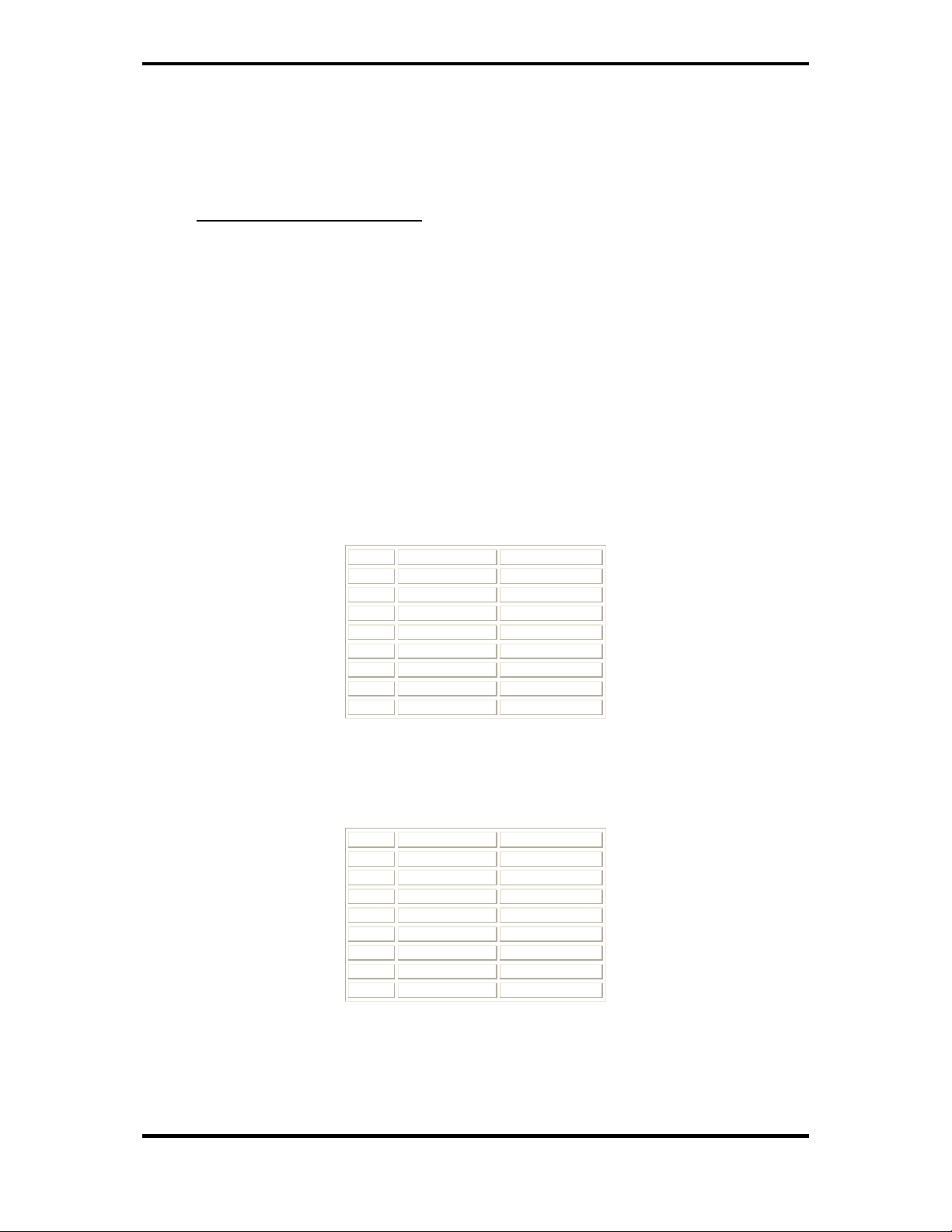
4.1 Serial Connections
Input Connections
PIN FUNCTION DIRECTION
1 0V GND
2 0V GND
3 TX- OUT
4 RX+ IN
5 RX- IN
6 TX+ OUT
7 +24V IN
8 +24V IN
The input serial connector(s) is connected to any of the Display Ports on the TallyMan Controller
using a 1:1 RJ45 cable. The pin function of the o/p connector will be the reverse of that shown
above.
Output connectors
PIN FUNCTION DIRECTION
1 0V GND
2 0V GND
3 RX- OUT
4 TX+ IN
5 TX- IN
6 RX+ OUT
7 +24V IN
8 +24V IN
UMD PSU-22 8 V4.0
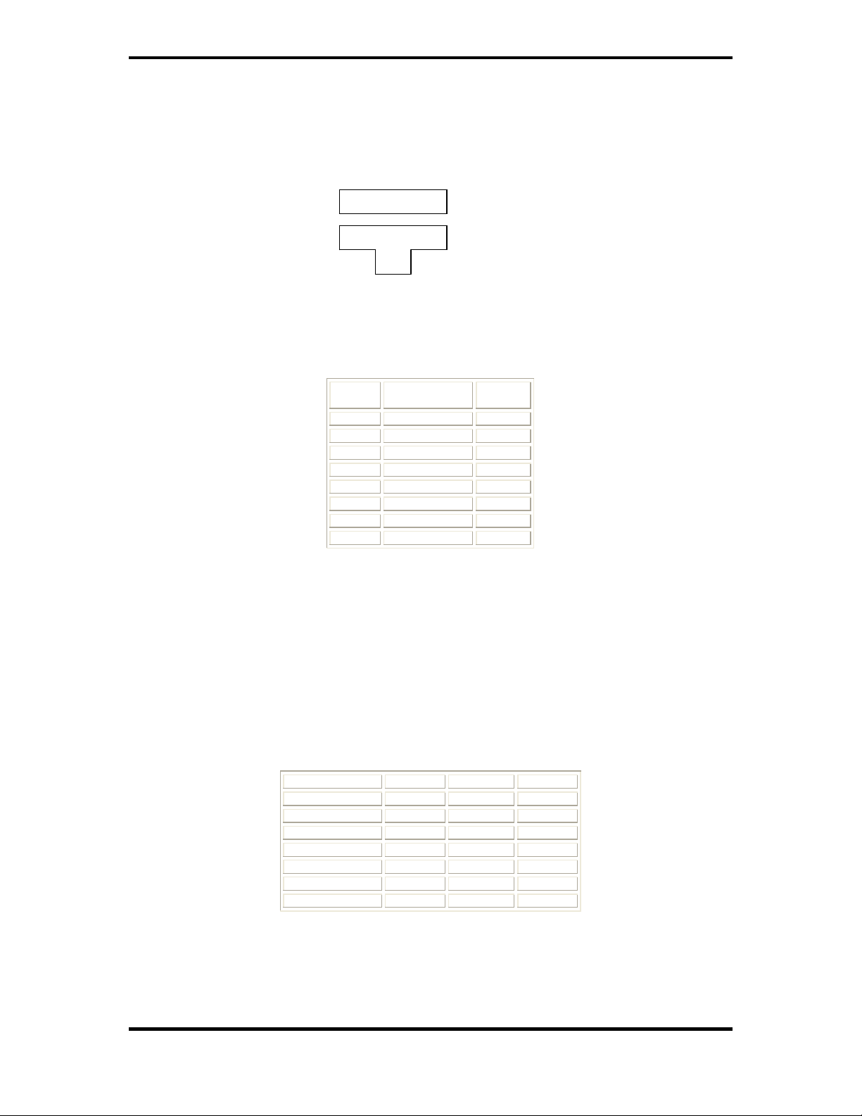
4.2 RJ45 Cable Connections
View from the back.
Cable entry.
RJ45 Connector on the cable
4.3 Adapter cable to connect RJ45 Displays to a D15 connector on a TSL UMD
RJ45 UMD
FUNCTION
D15M
1 0V 9
2 0V 10
3 TX- 14
4 RX+ 1
5 RX- 2
6 TX+ 13
7 +24V 7
8 +24V 7
4.4 The D25 Connector
This socket carries GPI alarm o/p information. In the good position, the relays are energised. The
table shows the unit in the good position with all modules fitted.
Pin out is as follows:-
Signal names common closed open
PSU MODULE A 14 1 2
PSU MODULE B 3 15 16
POWER BUS 17 4 5
SER1 PRESENT 6 18 19
SER2 PRESENT 20 7 8
SER1 STANDBY 23 10 11
SER2 STANDBY 9 21 22
SERx STANDBY means the signal is present, but other the channel is active.
1 2 3 4 5 6 7 8

UMD PSU-22 9 V4.0
5.0 Specifications
Single internal PSU – top IEC connector. PSU1
Width: 483mm Height: 88mm
Depth: 400mm Weight: 5.5Kgm
Input Power: 280W Operating Temp 5 ~ 25C
Output Power 240W
Twin internal PSUs – both IEC connectors
Width: 483mm Height: 88mm
Depth: 400mm Weight: 6.6Kgm
Input Power: 300W Operating Temp 5 ~ 25C
Output Power 240W
The depth figures do not include connector depth.
»It is suggested that an additional 100mm is allowed for the power IEC connector depth. This
will give enough space to allow removal of the connecter with the unit still in situ.

UMD PSU-22 10 V4.0
6.0 The Internal Power Supplies
These are Mean Well SP-300 Series units. In the event of a failure the faulty item should be returned
to TSL for replacement.
The user should not attempt any repairs as this voids the PSU manufacturer’s warranty.
Manufacturer’s Specification Model SP- 300-24
DC Output Voltage 24V
Output Voltage Tolerance 1%
Output Rated Current 12.5A
Output Current Range 0 – 12.5A
Ripple and Noise 150mV pk-pk
Line Regulation 0.2%
Load Regulation 0.5%
DC Output Power 300W
Efficiency 86%
DC Voltage Adjustment 20 ~ 26.4V
Input Voltage Range 88264VAC 4763Hz; 124~370VDC
AC Current 4A/115V, 2A/230V
Power Factor 0.9/100240VAC
Inrush Current 18A/115V 36A/230V
Leakage Current 1mA/240VAC
Overload Protection 105135% Type: Pulsing Hiccup Shutdown Reset:
Auto Recovery
Over Voltage Protection 27.6-32.4V
Fan Control Over Temp Protect. RTH1 or RTH250C Fan On, 45C Fan Off
70C Output Shutdown
Temp. Coefficient 0.03%/C (050C)
Setup, Rise, Hold up Time 1.5s, 50ms, 20ms
Vibration 10500Hz, 2G 10min./1cycle, Period for 60min each
axis
Withstand Voltage I/P-O/P:3KVAC I/P-FG: 1.5KVAC
O/P-FG:0.5KVAC
Isolation Resistance I/P-O/P, I/P-FG, O/P-FG:500VDC / 100Mohms
Working Temp. Humidity -10C-+50C (Refer to O/P de-rating Curve), 20%-90%
RH
Storage Temp. Humidity -20C+85C, 10%95% RH
Dimensions 215*115*50mm Case 912
Module weight 1.2Kgs
Safety Standards UL1950, TUV EN90950 Approved
EMC Standards CISPR22 (EN55022), IEC1000-4-2,3,4,5,6,8,11
IEC1000-3-2 Verification
Notes:
1. All parameters are specified at 230V I/P, rated load, 25C, 70% RH ambient
2. Ripple and noise are measured at 20MHz using a 12” twisted pair terminated with a 0.1uF and 47uF
capacitor.
3. Line regulation is measured from low line to high line at rated load.
4. Load regulation is measured for 0% to 100% rated load.

UMD PSU-22 11 V4.0
7.0 General Notes
1. It is recommended that the 0v/chassis connections are all connected together externally.
2. Allow 1RU above and below the unit for ventilation.
3. Do not exceed the maximum PSU-22 rating of 240W. This rating takes into account the internal
temperature rise limitations and is a safe maximum rating. Each RJ45 connector can supply up
to about 1.1A at +24V. This is to allow products such as the ML1 (which draws approx 800mA)
to be powered along with a combination of the standard displays up to a maximum of 240W.
4. For RJ 45 connected TSL equipment, the pin-out is 1:1.
5. The RJ 45 connectors must only be used to connect TSL UMD equipment together.
6. It is recommended that Category 5E FTP (foil screened twisted pair) cable is used. The
individual cores are rated at 1A at 24volts. Two cores are use for each power rail.
7. Each RJ45 output connector is individually buffered for both power and data from the others.
8. One PLU (Power Loading Unit) ≡2.5Watts
Table of contents


