SPECS HSA3500 User manual
HSA3500 /
HSA3500 plus
Power Supply
User Manual
Version 1.9

All rights reserved. No part of this manual may be reproduced
without the prior permission of SPE S GmbH.
User manual for the HSA3500 / HSA3500 plus Power Supply.
Version 1.9 printed 23 August 2010.
SPE S order number for this manual: 78 000 186
HSA3500 / HSA3500 plus Power Supply
SPECS GmbH - Surface Analysis
an Computer Technology
Voltastrasse 5
13355 Berlin
GERMANY
PHONE:+49 (0)30 46 78 24 -0
FAX: +49(0)30 4 64 20 83
http://www.specs. e

Chapter
T Table of Contents
1 Introduction 1
1.1 Preface.........................................................................................1
1.2 General Information...................................................................1
1.3 Physical Specifications................................................................2
1.4 Safety Instructions......................................................................3
1.5 Initial Inspection and Packaging List.........................................3
1.6 E 10 an-Ethernet-Adapter.......................................................4
1.6.1 Introduction.............................................................................................4
1.6.2 onnectors, diagnostic LEDs and switches.............................................5
1.6.3 Power Requirements...............................................................................6
1.6.4 Pin Setting of the AN Bus onnector...................................................6
1.6.5 Galvanic Decoupling................................................................................7
1.6.6 Propagation Delay...................................................................................7
1.7 Front / Back Panel Description...................................................8
1.8 General Internal Layout...........................................................10
1.9 Modules.....................................................................................11
1.10 HSA Ranges...............................................................................12
2 Using the HSA 13
2.1 Installation................................................................................13
2.1.1 Vacuum interlock...................................................................................13
HSA3500 / HSA3500 plus Power Supply

Table of ontents
2.2 Software for Interfacing with the HSA...................................14
2.3 Troubleshooting.......................................................................14
2.3.1 Diag-Tool................................................................................................15
2.3.2 onnection check for the analyzer electrodes.....................................18
2.3.2.1 heck all analyzer (HSA) voltages...................................................18
2.3.2.2 Fast heck of Voltage Ranges (energy scale).................................19
2.3.2.3 heck/set offset and gain with voltmeter......................................20
2.3.2.4 Fast check of all applied voltages...................................................21
2.3.3 hecking the Analyzer Voltages with ustom Setttings.....................26
3 HSA config files (*.hsa) 27
3.1 What are HSA3500 onfiguration Files?................................27
3.2 Nomenclature...........................................................................28
3.2.1 Mode......................................................................................................28
3.2.2 DA Voltage............................................................................................28
3.2.3 Natural ubic Spline..............................................................................28
3.2.4 Syntax and Encoding.............................................................................28
3.2.5 omments..............................................................................................29
3.2.6 Header....................................................................................................29
3.2.7 Sections..................................................................................................29
3.2.8 Entries.....................................................................................................30
3.2.9 Inheritance.............................................................................................31
3.2.10 Sections and Layout...............................................................................31
3.2.10.1 Info section......................................................................................31
3.2.10.2 SplineList Section.............................................................................32
3.2.10.3 LogicalVoltageList Section.............................................................33
3.2.10.4 ModeList Section..............................................................................33
3.2.10.5 SplineDef section ...........................................................................34
3.2.10.6 LogicalVoltageDef Sections.............................................................35
3.2.10.7 Macro Sections.................................................................................36
3.2.10.8 ModeDef Sections............................................................................37
3.2.11 Adding ustom Voltages.......................................................................44
HSA3500 / HSA3500 plus Power Supply

Table of ontents
3.3 onfig heck..............................................................................45
4 Appendix 47
4.1 Working Ranges........................................................................47
4.2 HSA modules.............................................................................53
4.2.1 0xf1 – 3.5kV bipolar (HSA3500 module)...............................................54
4.2.2 0xe1 – 400V bipolar (HSA3500 module)...............................................55
4.2.3 0xd1 – 3.5kV unipolar (HSA3500 module)............................................56
4.2.4 0xb1 – 150mA bipolar (HSA3500 module)............................................57
4.2.5 0x04 – 3.5kV Lens bipolar (HSA3500 plus module)..............................58
4.2.6 0x14 – 3.5kV analyzer bipolar (HSA3500 plus module).......................59
4.2.7 0x24 – 400V bipolar (HSA3500 plus module)........................................60
4.2.8 0x34 – 3.5kV unipolar (HSA3500 plus module)....................................61
4.2.9 0x44 – 150mA bipolar (HSA3500plus module).....................................62
4.3 Hardware type and backplane wiring....................................63
4.3.1 Wiring I...................................................................................................65
4.3.2 Wiring H.................................................................................................66
4.3.3 Wiring Q.................................................................................................67
4.3.4 Wiring X1...............................................................................................68
4.3.5 Wiring X4...............................................................................................69
4.4 The Filterbox cable...................................................................70
4.4.1 Interlock connections............................................................................70
4.4.2 Pin Assignment......................................................................................70
4.5 HSA3500 Tool............................................................................71
4.5.1 ommands Explained............................................................................75
4.5.2 Error Messages of the Diagnostic and Programming..........................78
HSA3500 / HSA3500 plus Power Supply


Chapter
1Intro uction
1.1 Preface
This manual describes the entire HSA3500 and HSA3500 plus power supply manufac-
tured by SPE S. For all common features we will use the term ”HSA” for both. When it
is necessary to point out specific features, we will use the terms HSA3500 and HSA3500
plus, respectively.
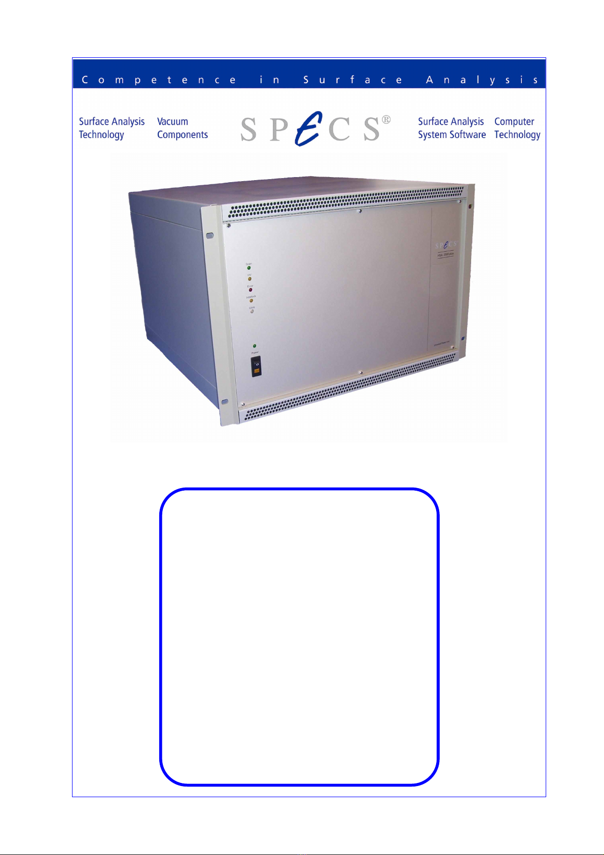
1.2 General Information
With the HSA 3500 plus SPE S presents a new versatile high voltage power supply for
electrostatic field applications. The HSA3500 plus is the further development of
HSA3500. The modular design of the unit allows independent setting of all voltages -
no voltage dividers are used.
Each module is fully galvanically floating, highly stable and linear. The voltages are con-
trolled by high-precision 24-bit digital-to analog converters with an overall maximum
settle time of 3 ms.
The HSA consists of a main PU and various voltage and current modules. All commu-
nication goes over the AN -Bus to the main PU. The main PU distributes all AN -
Bus messages to respective modules. The device provides +5V, +15V for the modules
and main PU, and +24V for external devices via AN-Bus (e.g. E 10). On the back pan-
el you connect all the hardware to the analyzer (e.g. SPE S Phoibos) and detector (e.g.
HSA3500 / HSA3500 plus Power Supply 1
Introduction
SPE S D detector). On the front panel you can switch the HSA on, off and get the
device status via LEDs.
Every module is calibrated with a high precision voltmeter by SPE S. That means the
DA values are assigned to voltages or current values and stored in the EEPROM
(flash) from the module.
1.3 Physical Specifications
Size: L x W x H, 45cm x 32cm x 50cm
Weight: approx. 15kg depending on configuration
Data onnection: AN-Bus (500 kBaud)
Line Input: 100V – 250V, 47 – 63Hz
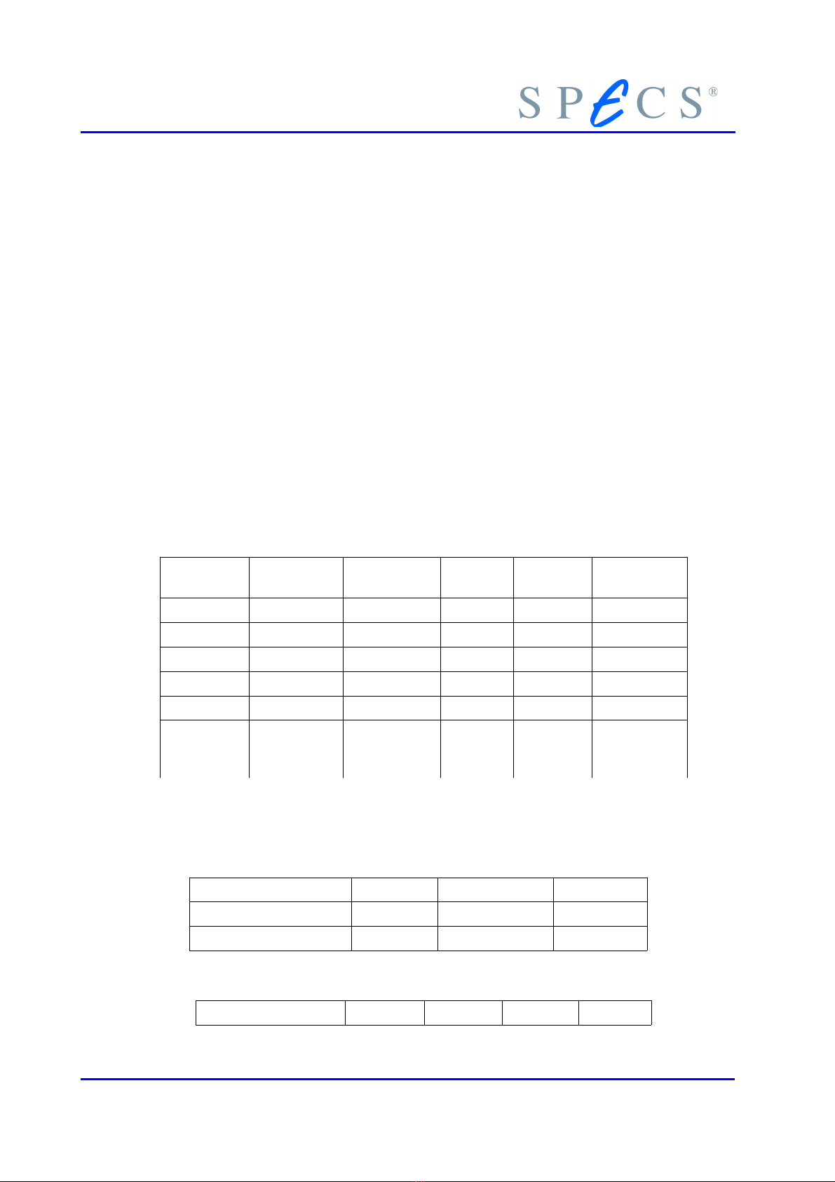
The HSA3500 plus has 5 additional modules, with specifications given below:
3,5kV Bi Lens 3,5kV Bi
Analy
3,5kV Uni 400V Bi PU / 150mA
Resolution 20 Bit 20 Bit 16 Bit 20 Bit 13 Bit
DA s 1 1 1 3 1
Relays 2 2 1 0 0
Ranges 4 2 1 3 1
TK 2.5 ppm 1.5 ppm - 2.5 ppm n / a
Long Term
(one year
operation)
400 ppm 50 ppm - 50 ppm -
These individual modules also have their own voltage characteristics:
400V Bi:
Range +/- 400V -20V / +100V +/- 10V
Step size 805µV 125µV 20µV
Noise (with filterbox) < 200µV < 250µV
3,5kV Bi Lens:
Range +/- 3500V +/- 1500V +/- 600V +/- 150V
2HSA3500 / HSA3500 plus Power Supply
Step Size 7,2mV 3,1mV 1,27mV 318µV
Noise (with filterbox) < 850µV < 400µV < 100µV < 50µV
3,5kV Bi Analy :
Range +/- 3500V +/- 1500V
Step Size 7,1mV 1,7mV
Noise (with filterbox) < 600µV < 500µV
1.4 Safety Instructions
Before performing any electrical or electronic operations, please consult ‘SPECS
Safety Instructions’ an follow them closely. Please consult as well any ocumenta-
tion of supplie material from thir party manufacturers before any operation an
strictly follow the safety instructions given therein.
1.5 Initial Inspection an Packaging List
Visual inspection of the component is required to ensure that no damage has oc-
curred during shipping. Should there be any signs of damage or parts missing, con-
tact SPE S immediately. Please check the delivery according to the packaging list for
completeness.
Quantity Item
1 HSA3500 or HSA3500 plus
1 Printed HSA3500 Manual
1 Power cord (200V or 115V)
2 AN-Bus cable
2 AN-Bus terminator
2 HV cable ( hannel HV, hannel Base)
1 HV cable (Screen) optional
1 HV Interlock override connector
1 E 10 an-Ethernet-Adapter
1 Ethernet cable
HSA3500 / HSA3500 plus Power Supply 3

Introduction
1 Specification sheet (optional)
Table 1: Packaging List of the HSA
1.6 EC10 Can-Ethernet-A apter
1.6.1 Intro uction
The E 10 is an external AN-Bus adapter for the P . It is connected to the P via an
ethernet network. The P 's access to AN-Bus controlled devices like the HSA is
provided by the E 10 and the communication between P and E 10 is handled by
the standard T P/IP network protocol.
Figure 1: Rear Side of the E 10
Figure 2: Front Side of the E 10
4HSA3500 / HSA3500 plus Power Supply

1.6.2 Connectors, iagnostic LEDs an switches
Each connector, LED, and switch is labelled, and their purpose is described below.
Label Type Description
Ethernet RJ45 Ethernet Network onnector
AN DB9 connector male AN-Bus onnector
AN DB9 connector female AN-Bus onnector
RS-232 DB9 connector female Serial port. Not used in normal operation. Do
not connect anything to this connector.
24V D socket onnector for external power supply. Not used
in normal operation. Power supply is provided
via the AN-Bus.
TX LED green Ethernet transmit activity indicator. This LED
will flash while the E 10 is transmitting data
on the network.
LNK LED green Ethernet link indicator. This LED will flash if
the data link between the E 10 and the
HUB/switch is estalished.
RX LED yellow Ethernet receive activity indicator. This LED
will flash while the E 10 is receiving data from
the network.
ONL LED red This LED will flash while the P software is
connected to the E 10, e.g. while SpecsLab is
running.
AN LED green AN Bus activity indicator. This LED will flash,
while the E 10 receives or transmits AN Bus
packets.
SER LED yellow Serial interface activity indicator. This LED will
not flash in normal operation.
PWR LED green Power indicator. This LED will flash, as long as
24 Volt power is applied to E 10.
FG Push-button This button is used to initiate the con
figuration of the IP-Address by the use of
E 10 onfig program. The usage of E 10 onfig
is described in QuickGuide-E 10.pdf.
Table 2: LEDs and onnectors of the E 10
At power-up the E 10 will execute a self-test sequence that is indicated by quickly
(300 Milliseconds) flashing the diagnostic LEDs “PWR”, “ AN”, “ONL” and “SER”. If
the self-test is successful, the “PWR” LED will remain on, the other LEDs are turned
HSA3500 / HSA3500 plus Power Supply 5

Introduction
off. If the self-test fails, the “PWR” LED will blink with a frequency of 2 Hertz and
the other LEDs will indicate the reason of failure. In this case the device will not be
operable and should be returned to SPE S for service.
If no LED flashes at all, the presence of the 24 Volt power supply should be checked.
ontact SPE S for furter advice.
1.6.3 Power Requirements
The E 10 needs a 24 Volt supply voltage. Usually this voltage is provided by the HSA
via the AN-Bus cable. A 24 Volt supply voltage can be fed to the E 10 via the D
socket labelled “24V” at the front side of the housing as well. The typical current
drain of the device is 48 mA.
1.6.4 Pin Setting of the CAN Bus Connector
The Pin setting of the AN BUS connector is given in table 6, the naming is depicted
in figure 3.
AN Bus Pin Name
1 +24V
2 AN Low
3 0V
4 +24V
5 0V
6
7 AN High
8
9
Table 3: Pin setting of the AN Bus connector
6HSA3500 / HSA3500 plus Power Supply

Figure 3: AN Bus onnector (a common DBUS-9)
1.6.5 Galvanic Decoupling
The AN-Bus connection is opto-electrically decoupled. The ethernet connection is
magnetically decoupled. The electrical strength of both decouplings is greater than
500 Volts D .
1.6.6 Propagation Delay
The propagation delay is the time the E 10 needs to convert an ethernet packet into
a AN-Bus packet and vice versa. This time is approximately 190 microseconds in each
direction. The run-time of the ethernet packet (approximately 50 microseconds) adds
to this time.
HSA3500 / HSA3500 plus Power Supply 7
Introduction
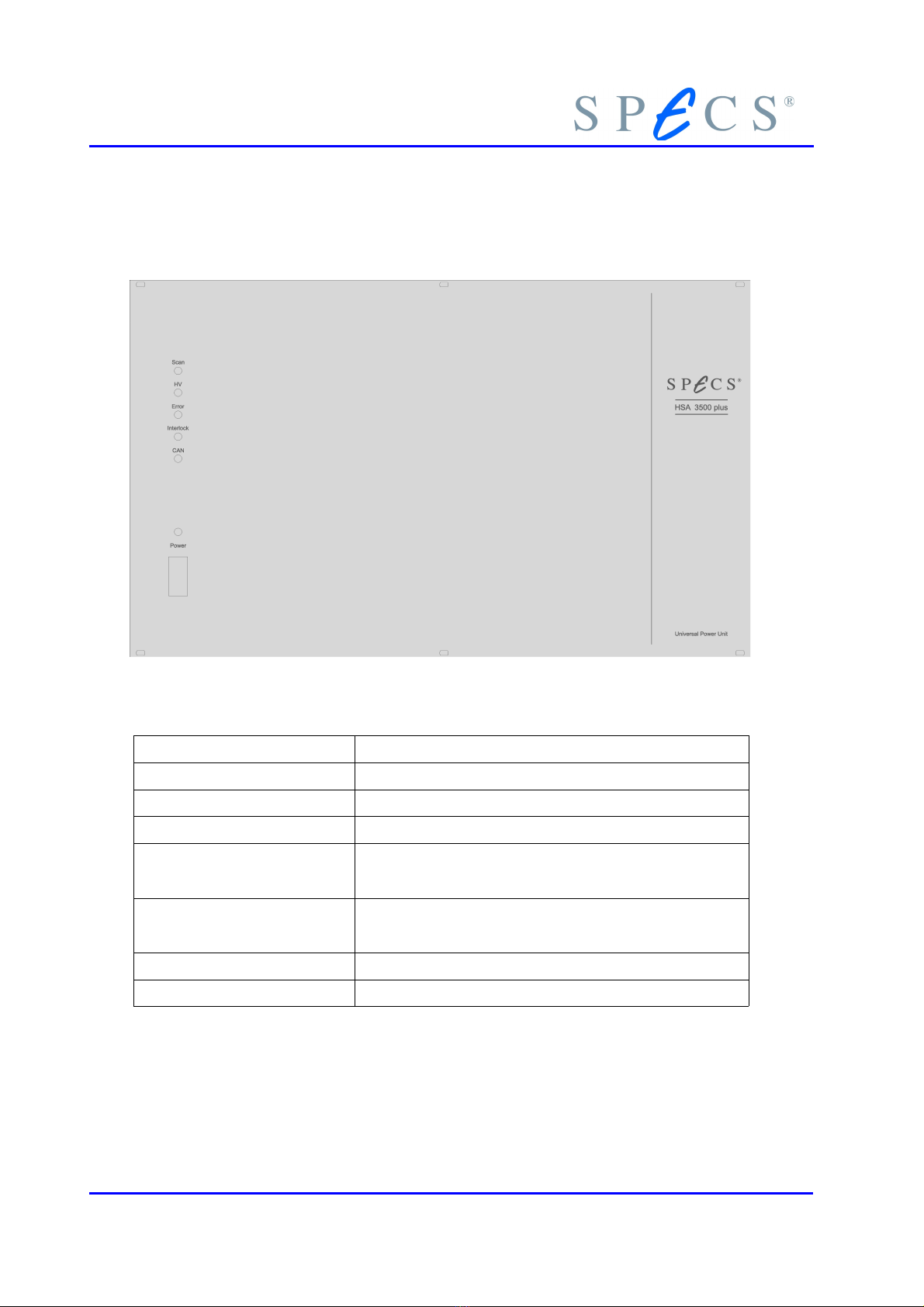
1.7 Front / Back Panel Description
Figure 4: HSA3500 plus front panel
Label Description
LED Scan (green) urrently measuring (e.g. with SPE SLAB)
LED HV (yellow) The high voltage output is activated.
LED Error (red) Error - something not to specifications
LED Interlock (yellow) This LED will be on if the (vacuum)interlock, is en-
gaged.
LED AN (green) This LED will blink while the HSA is not connected
and will be on while the HSA is connected to P .
LED Power (green) This LED will be on when HSA is powered up.
Power Switch Switches the HSA on or off
Table 4: HSA3500 plus front panel description
8HSA3500 / HSA3500 plus Power Supply
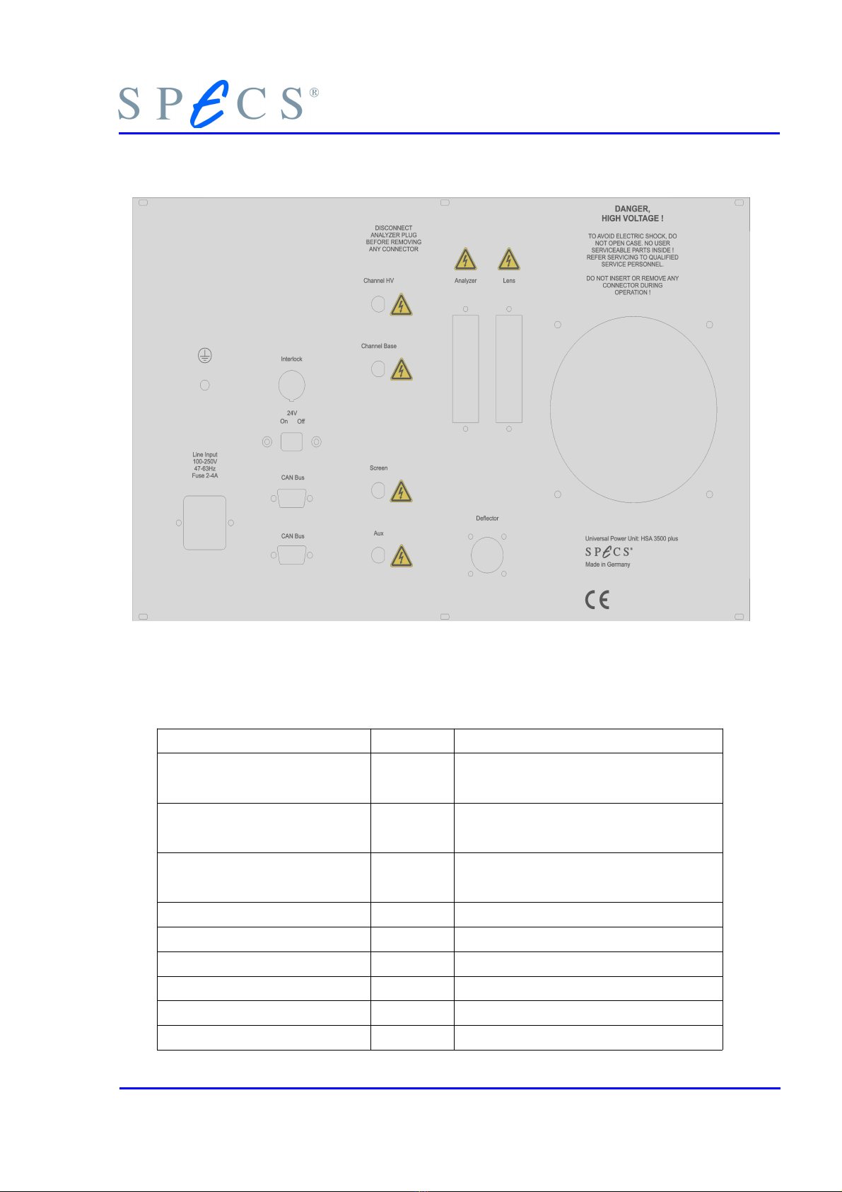
Figure 5: HSA3500 plus back panel
Label Type Description
hannel HV SHV onnection to electron multiplier out-
put (detector andode)
hannel Base SHV onnection to electron multiplier input
(detector cathode)
Screen or DLD SHV onnection to detector ( D, DLD
only)
Mesh or Aux SHV onnection defined by user
Line Input 3pin Input for power cord
Interlock 3pin Interlock connector
Sliding Switch Activate the 24V on AN-Bus connector
AN BUS Sub-D 9pin onnection to AN-Bus (Male)
AN BUS Sub-D 9pin onnection to AN-Bus (Female)
HSA3500 / HSA3500 plus Power Supply 9
Introduction
Deflector 6 pin onnection to deflector (optional)
analyzer 30pin onnection to analyzer (Phoibos)
Lens 30pin onnection to lens (Phoibos)
Fan ooling the unit
Grounding Screw 1pin onnection to ground
Table 5: HSA3500 plus back panel description
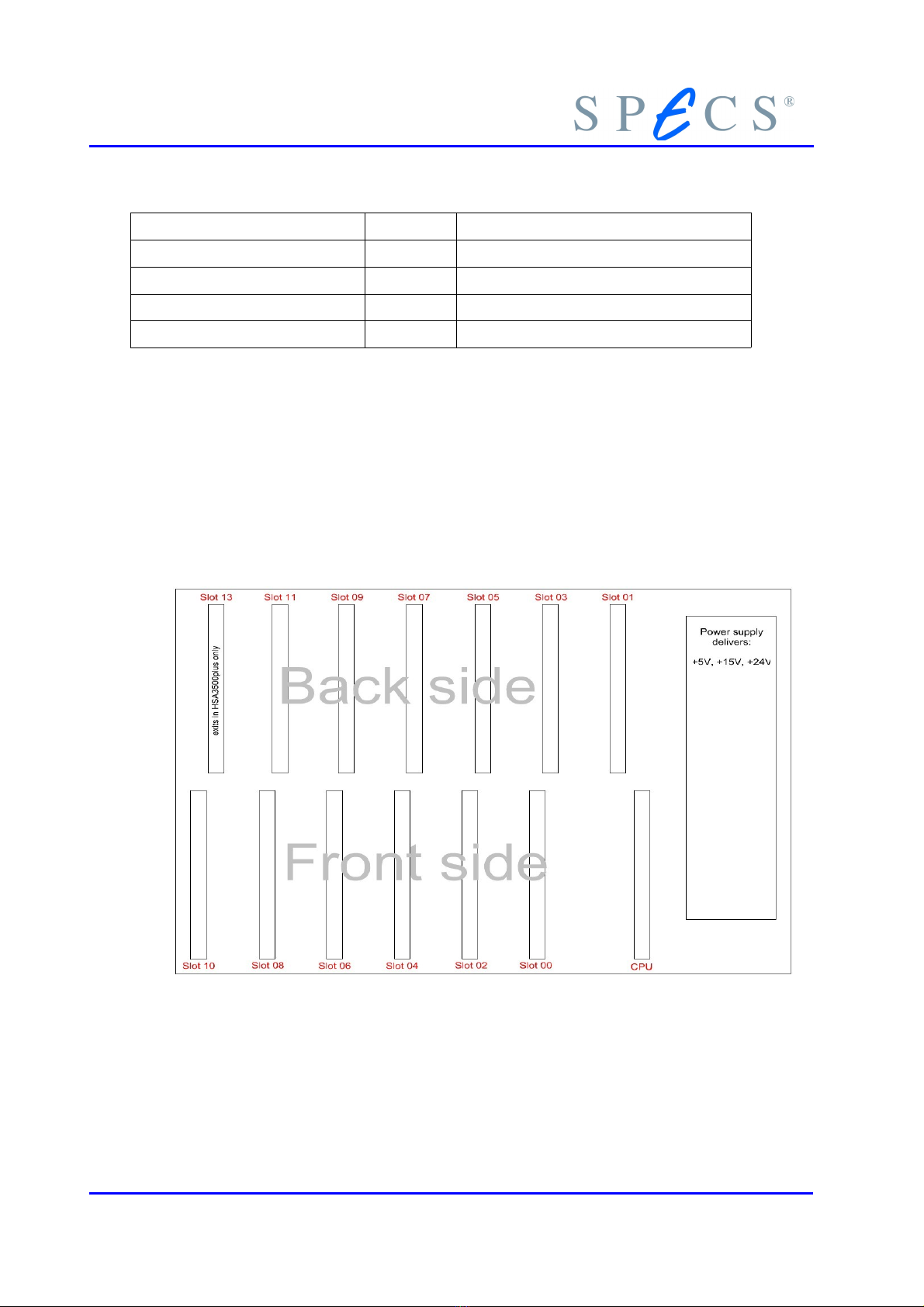
1.8 General Internal Layout
In Figure 6 you can see the general internal layout of the HSA. At the front side you
have the even slot numbers and on the back side you have the odd slot numbers. The
slot configuration depends on hardware and wiring type. For details see Table 42 in
the Appendix.
Figure 6: HSA General Internal Layout
10 HSA3500 / HSA3500 plus Power Supply
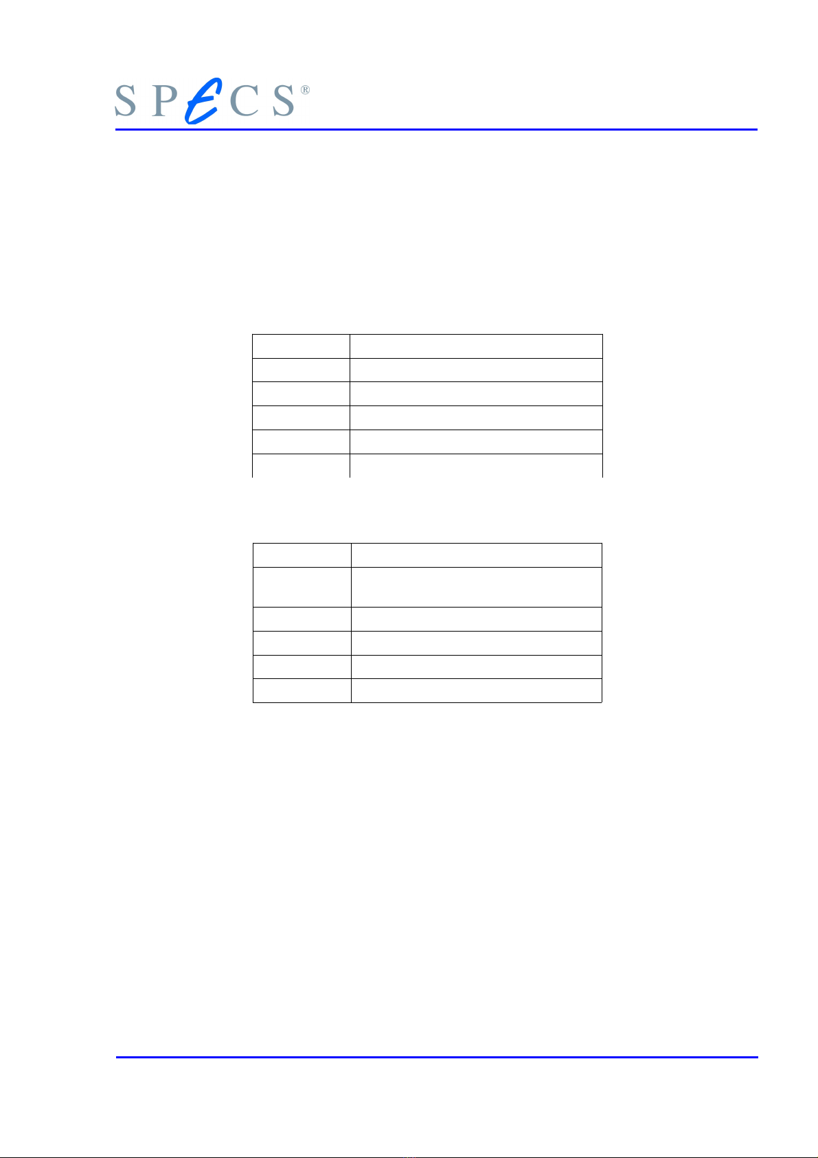
1.9 Mo ules
There are different modules within the HSA. All modules have an internal type num-
ber (Table 6 and Table 7). Every module has a serial number and production date
printed on the board.
Type Name
- Main PU
0xf1 3.5kV bipolar
0xe1 400V bipolar
0xd1 3.5kV unipolar
0xb1 150mA unipolar
Table 6: HSA3500 modules
Type Name
- Main PU with current module
150mA
0x04 3.5kV Lens bipolar
0x14 3.5kV Analyzer bipolar
0x24 400V bipolar
0x34 3.5kV unipolar
Table 7: HSA3500 plus modules
HSA3500 / HSA3500 plus Power Supply 11
Introduction
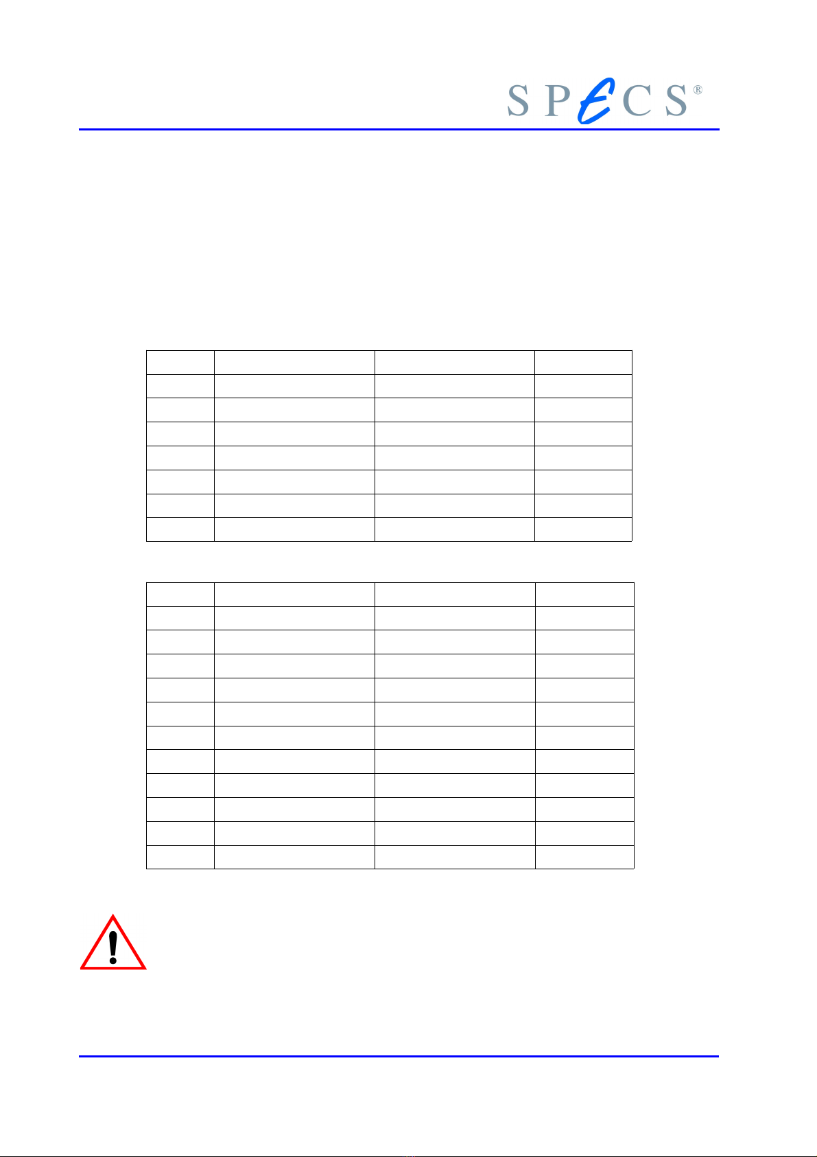
1.10 HSA Ranges
The SPE S power supply HSA3500 has one main PU and four modules with different
voltage ranges. Smaller voltage ranges has always a better resolution. See Table 8 for
details. The SPE S power supply HSA3500 plus has one main PU with current mod-
ule on board and four modules with different voltage ranges. See Table 9 for details.
Type Module Min. Voltage Max. Voltage
Main- PU
0xf1 3.5kV -3500V +3500V
0xf1 3.5kV -1500V +100V
0xe1 400V -400V +400V
0xe1 400V -40V +40V
0xd1 3.5kV uni -0.1V +3500V
0xb1 150mA 0mA 150mA
Table 8:
HSA3500
Ranges
Type Module Min. Voltage Max. Voltage
Main- PU 0mA 150mA
0x04 3.5kV Lens -3500V +3500V
0x04 3.5kV Lens -1500V +1500V
0x04 3.5kV Lens -600V +600V
0x04 3.5kV Lens -150V +150V
0x14 3.5kV analyzer -3500V +3500V
0x14 3.5kV analyzer -1500V +100V
0x24 400V -400V +400V
0x24 400V -100V +20V
0x24 400V -10V +10V
0x34 3.5kV unipolar +3500 -100
Table 9:
HSA3500 plus Ranges
Don't mix HSA3500 mo ules with HSA3500 plus
mo ules in the same evice.
12 HSA3500 / HSA3500 plus Power Supply
Chapter
2Using the HSA
2.1 Installation
For installation see PHOIBOS Manual (SPE S order number: 78 000 101).
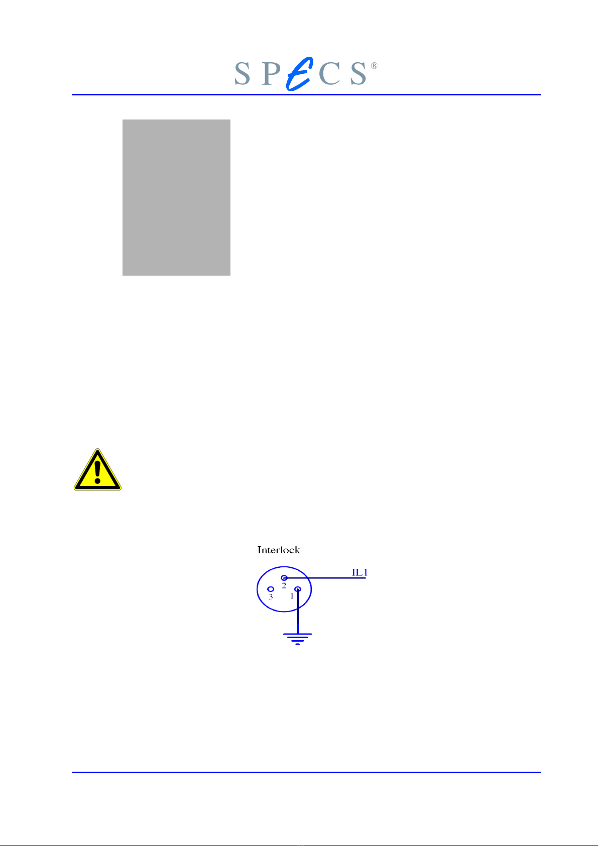
2.1.1 Vacuum interlock
For operation of the HSA the vacuum interlock connector has either to be connected to
a pressure gauge or must be bridged temporarily with the supplied connector.
Bri ging the vacuum interlock can cause great amage in case of su en pressure rise.
Use at your own risk!
The pin setting of the connector is shown in figure 7. So to bridge the interlock the pins
1 and 2 have to be shortend.
Figure 7: Vacuum interlock connector
HSA3500 / HSA3500 plus Power Supply 13

Using the HSA
2.2 Software for Interfacing with the HSA
Your options for controlling the HSA are:
●SpecsLab2, including the HSA Juggler.
●ustom made programs using the SpecsLab DLL “SL2_AD.dll”, see SL2_AD.h
and the Software 2D Manual (SPE S order number: 78 000184)
●National Instruments' Labview® is also supported using the special DLL
SL2_AD_VI.dll. SPE S provides also a sample VI in the folder programming in
side the SPE SLab2 software package. For implemenation tips
seeSL2_AD_DLL_Test.vi and SL2_AD.h from this software package.
●Other possibilities are remote control of applications like SpecsLab2 using
Windows Messages
●Using directly the public ORBA-interfaces of the SPE S device drivers is also
possible but intermediate programming skills is for this solution a good
thing.
●A low level tool for advanced users called “hsa3500tool” is also available. See
chapter 4.5 on page 71.
2.3 Troubleshooting
This chapter provides a guide for troubleshooting problems with the HSA. Possible
problems fall into three categories.
1. More than one beep after switching the HSA on
- Incorrect hardware type
- Module is in wrong slot or module is missing
2. Error LED (red) on front panel is on
- Recalibrating from one or more modules faulty (HSA3500 only)
- No firmware
- AN-Bus error
14 HSA3500 / HSA3500 plus Power Supply
This manual suits for next models
1
Table of contents
Other SPECS Power Supply manuals


