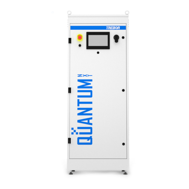
Trebor 2472 Manual

AUnitofIDEXCorporation
SERIAL NUMBER :
9/13/00 –M2472-FB
MODEL 2472
DI WATER HEATER
Operation / Maintenance
Manual

AUnitofIDEXCorporation
2472 DI HEATER OPERATION / MAINTENANCE MANUAL CONTENTS
CONTENTS
1INTRODUCTION........................................................................................................................3
2SAFETY .....................................................................................................................................4
2.1 SAFETY MESSAGE CONVENTIONS ............................................................................4
2.1.a Danger..............................................................................................................4
2.1.b Warning............................................................................................................4
2.1.c Caution .............................................................................................................5
2.2 EQUIPMENT SAFETY....................................................................................................5
2.3 INTERLOCKS.................................................................................................................5
2.3.a Over Temperature Controller Interlock (OTC) ..................................................5
2.3.b Low Pressure Switch Interlock..........................................................................6
2.3.c Liquid Level Sensor Interlock ...........................................................................6
2.3.d Panel Interlock Switches(is this section ok?)....................................................6
2.3.e Leak Sensor .....................................................................................................7
2.3.f Overpressure Burst Fitting................................................................................7
2.4 EMERGENCY OFF (EMO)..............................................................................................8
2.5 LOCKOUT / TAGOUT.....................................................................................................8
2.5.a Preliminary........................................................................................................8
2.5.b Definitions.........................................................................................................8
2.6 SEISMIC PROTECTION.................................................................................................9
3INSTALLATION .......................................................................................................................10
3.1 UNPACKING.................................................................................................................10
3.2LOCATION....................................................................................................................10
3.3 UTILITY REQUIREMENTS...........................................................................................11
3.4 HOOK-UP .....................................................................................................................13
3.5 REMOTE HOOK-UP.....................................................................................................16
4OPERATION ............................................................................................................................17
4.1 GENERAL.....................................................................................................................17
5START-UP ...............................................................................................................................19
5.1 PRE-START INSPECTION...........................................................................................19
5.1.a Verify Shipping Condition ...............................................................................19
5.1.b High Power Terminals ....................................................................................19
5.1.c Electrical Inspection........................................................................................19
5.1.d Plumbing Leak Check.....................................................................................19
5.2 SYSTEM ON.................................................................................................................20
5.3 TEMPERATURE CONTROLLER..................................................................................20
5.4 HEATER MODULE POWER.........................................................................................21
5.5 POWER DISTRIBUTION INDICATORS.......................................................................21
6SHUT DOWN ...........................................................................................................................22
6.1 HEATER CLEANOUT...................................................................................................22
7MAINTENANCE.......................................................................................................................23
7.1 REPAIR INSTRUCTIONS.............................................................................................23
7.1.a Heater Element Check....................................................................................23
7.1.b Fuse Replacement .........................................................................................23
7.1.c Draining the System .......................................................................................24
7.1.d Leaks..............................................................................................................24
7.1.e Overpressure Relief Replacement..................................................................25
7.1.f Heater Replacement.......................................................................................26
7.2 SPARE PARTS.............................................................................................................27
7.3 PREVENTIVE MAINTENANCE SCHEDULE................................................................27
7.4 HEATER CALIBRATION...............................................................................................28
8TROUBLESHOOTING.............................................................................................................31
8.1 TEMPERATURE CONTROLLER DOES NOT DISPLAY..............................................31
8.2 ALARM SOUNDS .........................................................................................................31
8.3 HEATER ELEMENT STATUS LED IS ON....................................................................32
9WIRING SCHEMATIC..............................................................................................................33
10 WARRANTY.............................................................................................................................34

AUnitofIDEXCorporation
2472 DI HEATER OPERATION / MAINTENANCE MANUAL PAGE 3
1 INTRODUCTION
2472 DI WATER HEATER
Proven advantages associated with using high purity DI water at elevated
temperature include: faster rinse time to purity, elimination of substrate
streaking, less water consumption for rinsing and increased product
throughput.
This system employs a simple, compact design, which minimizes the use
of cleanroom floor space. The heater systems temperature sensors,
controls and heaters are constructed for tight control of the process
temperature even in the extent of large process flow changes. DI water
contacts only high purity fluoropolymer materials (PVDF, PFA, and
PTFE). The modular system design facilitates the addition or
replacement of system components as the need arises. Redundant,
built-in safety features and heater diagnostics provide valuable user
protection and performance feedback.
With proper care and maintenance, the Model 2472 DI Water Heater
System has proven itself reliable with many years of installed heater run
time, resulting in substantial cost saving through increased productivity.
This equipment complies with the semiconductor manufacturing industry
requirements of SEMI S2-0200:
Figure 1-1: “SEMI S2-0200”
Conformity of the equipment with the above guidelines is attested by the
TUV certification mark.

AUnitofIDEXCorporation
PAGE 4 2472 DI HEATER OPERATION / MAINTENANCE MANUAL
2 SAFETY
This section describes the safety-related information that is important for
safe equipment operation. Included is a listing of message conventions
used in this manual as well as equipment safety interlocks, pushbuttons,
and labels.
The equipment described in this manual uses high-voltage electricity that
can be dangerous. Only personnel trained in the procedures and safety
messages outlined in this manual should install (if applicable), operate, or
maintain this equipment. Read and understand this manual before
installation or operation of the system. Follow all recommended practices
and procedures that apply to your actions and conduct. All safety guard
devices must be in place when equipment is in operation. Operators, set-
up operators, helpers or installation personnel should not alter, remove or
disable safety equipment. When using this equipment, be sure to follow
the safety procedures outlined by your facility. These safety procedures
should cover the two primary types of hazard training: (1) equipment
hazards, and (2) facility-related hazards.
2.1 SAFETY MESSAGE CONVENTIONS
Safety messages contained in this manual, Dangers, Warnings, and
Cautions are highlighted for quick identification.
2.1.a Danger
A Danger message indicates an imminently hazardous situation that, if
not avoided, will result in death or serious injury. Messages identified by
the word Danger are used sparingly and only for those situations
presenting the most serious hazards.
2.1.b Warning
A Warning message indicates a potentially hazardous situation that, if not
avoided, could result in death or serious injury. Following is a typical
example of a Warning message as it could appear:

AUnitofIDEXCorporation
2472 DI HEATER OPERATION / MAINTENANCE MANUAL PAGE 5
2.1.c Caution
A Caution message indicates a potentially hazardous situation, which, if
not avoided, could result in minor or moderate injury. It may also be used
to alert against unsafe practices. Following is a typical example of a
Caution message as it could appear:
2.2 EQUIPMENT SAFETY
The rest of this section describes equipment safety features:
Equipment Safety Interlocks
Emergency Off Pushbuttons
Main Power Disconnect Switch
Lockout/Tagout Information
Equipment Safety Labels
Hazard Lights
2.3 INTERLOCKS
! WARNING: The high voltage interlock circuit does not remove high
voltage from the circuit breaker, contactor, and the control
transformer. Only authorized, qualified, trained personnel should
service this equipment.
2.3.a Over Temperature Controller Interlock (OTC)
The OTC disengages power to the heater components when it detects a
heater module temperature over 105C (221F). The over temperature
fault LED will indicate a failure has occurred and the display of the OTC
causing the fault will flash “ALR”. The OTC’s will disengage power and a
manual reset will be required by pressing HEATER ON (see Section 8,
Troubleshooting).

AUnitofIDEXCorporation
PAGE 6 2472 DI HEATER OPERATION / MAINTENANCE MANUAL
!CAUTION: Do not change OTC temperature settings. These units
are factory set and sealed at 105°C (221F). Any change to the
setpoint of these over temperature controller devices may damage
the heater modules and will void the system warranty.
2.3.b Low Pressure Switch Interlock
The pressure switch will disengage power when heater module pressure
drops below 22-25 psig. DI water pressure is required for efficient heat
transfer. Operating the heater at lower pressure can damage heater
elements. The system will require pressing HEATER ON to restart (see
Section 8, Troubleshooting).
2.3.c Liquid Level Sensor Interlock
The Liquid Level Sensor will disengage power to the system if the heater
modules are not full of water and prevents them from running dry. The
system will require pressing HEATER ON to restart (see Section 8,
Troubleshooting). If sensor calibration is required, follow directions in
Section 7.4.
2.3.d Panel Interlock Switches(is this section ok?)
The “Positive-Break” panel interlock switches will disengage power to the
system when the control panel on the system is opened (see Figure 2-1:
Panel Interlock Locations). Replacing panels and pressing HEATER ON
will be required to restart heater.
Figure 2-1: Panel Interlock Locations
Troubleshooting

AUnitofIDEXCorporation
2472 DI HEATER OPERATION / MAINTENANCE MANUAL PAGE 7
Condition: System will not start if a panel is removed or interlock
switches are not operating properly.
Solution: Check that heater panels are secure, review condition of
panel interlock switches; replace if necessary.
2.3.e Leak Sensor
The Leak Sensor will disable heater power immediately when water is
detected in the leak tray and the corresponding fault LED will illuminate.
The fault condition is caused by a plumbing leak inside the heater. Fix
any leaks and dry the leak tray prior to turning power on to the system.
The heater can be reactivated by pressing the HEATER ON button and
will not function until the fault condition clears.
Figure 2-2
2.3.f Overpressure Burst Fitting
The overpressure burst fitting (“Relief Drain”) is connected in-line with the
cold DI inlet port to provide a safeguard against possible overpressure
damage. Do not operate the heater above 60-psig (4.1 bar).
If the overpressure relief device opens, the low pressure sensor can
disable heater power when an alarm condition exists and the pressure
fault LED will illuminate. Refer to Section 7.1.e on replacing burst fitting.

AUnitofIDEXCorporation
PAGE 8 2472 DI HEATER OPERATION / MAINTENANCE MANUAL
2.4 EMERGENCY OFF (EMO)
The EMERGENCY OFF button (EMO) is located on the front of the
Control Panel. When the EMO circuit is activated by pushing button in,
the equipment will be placed into a safe shutdown condition. The EMO
circuit de-energizes all electrical control power to the equipment. Only
the supply voltage and supply to EMO switch are energized when the
EMO is in the OFF position.
Figure 2-3
2.5 LOCKOUT / TAGOUT
2.5.a Preliminary
Before installation or servicing the DI water heater, the facility’s circuit
breaker or power source must be de-energized to prevent serious injury
to personnel and equipment. An authorized employee representing the
facility installing the DI water heater must follow approved company
guidelines and lockout or use suitable means to prevent re-energizing the
electrical system during installation or servicing.
2.5.b Definitions
Lockout: the placement of a lockout device on an energy isolating
device, in accordance with established company procedures, ensuring
that the energy isolating device and the equipment being controlled
cannot be operated until the lockout device is removed.
Tagout: a prominent warning device such as a tag and a means of
attachment, which can be securely fastened to an energy isolating device
in accordance with established company procedure, to indicate that the
energy isolated device and the equipment being controlled may not be re-
energized or operated until the tagout device is removed.
A simple Lockout device is provided with each system. The Lockout is
tethered to the main circuit breaker.
Always perform an electrical de-energization test before and after
installation of the Lockout device by verifying the circuit breaker
properly isolates the line voltage from the system.

AUnitofIDEXCorporation
2472 DI HEATER OPERATION / MAINTENANCE MANUAL PAGE 9
Place the circuit breaker in the OFF position
Place the Lockout device over the switch.
Tighten the set screw securely with a 1/8” or smaller flathead
screwdriver. Typically, two (2) complete revolutions of the setscrew
are required after the screw first touches the switch. Do not over
tighten the setscrew. The circuit breaker switch may fracture.
Verify that the Lockout is adequately secured to the switch.
Insert a padlock through both holes. This will prevent access to the
setscrew. The Lockout device is designed for use with 9/32” diameter
shackle padlocks. Smaller diameter padlocks may not adequately
block access to the setscrew.
Verify that the circuit breaker switch cannot be repositioned to ON.
Attach a safety tag.
Use the following information to assist in writing Lockout/Tagout
procedures for the system. For more specific instructions, refer to your
site’s Lockout/Tagout requirements and procedures.
This table lists the Lockout/Tagout information for the system.
Energy Type
Electrical
Hazard:
Electrocution, electrical burns, and shock
Magnitude:
480 VAC
Control Method:
Main Power –Disconnect Switch
Shutdown Procedure
Press Emergency Off
Switch off circuit breaker on front of system.
2.6 SEISMIC PROTECTION
It is the users responsibility to adequately secure and anchor the
equipment to comply with local regulatory agency seismic requirements.
Mechanical anchor locations are provided on the top and bottom of the
cabinet enclosure.

AUnitofIDEXCorporation
PAGE 10 2472 DI HEATER OPERATION / MAINTENANCE MANUAL
3 INSTALLATION
3.1 UNPACKING
Remove heater system from crate and inspect heater cabinet for any
signs of damage (dented panels, paint scratches, etc.). Shock indicators
inside the heater cabinet should be checked for rough handling during
shipment. Any damage to the system should be reported to the carrier
immediately.
!CAUTION: Heavy Object. When lifting or moving the system, follow
safe heavy object handling methods to prevent injury.
Be careful when using a dolly or forklift to not damage the drain fitting
located under the heater cabinet.
3.2 LOCATION
Locate the heater near the point-of-use to reduce plumbing heat loss.
Access to the front and rear of the system will be necessary for
maintenance and hook-up. For heater replacement, access to the top
and sides of the enclosure are required. This access can be achieved by
disconnecting the fluid and power hookups (see Section 2.6) and moving
the heater to a serviceable area.
NOTE: The DI water heater must be allowed to stabilize at installation
location at ambient temperature and humidity for 24 hours before
operation. Refer to Section 3.3 for system requirements.

AUnitofIDEXCorporation
2472 DI HEATER OPERATION / MAINTENANCE MANUAL PAGE 11
3.3 UTILITY REQUIREMENTS
Utility
2472 Heater
System Power:
480 volts, 3 phase, 50/60 Hz, 86 Amp Full Load
100A over-current protection provided at machine hook-
up terminals
Machine Interrupting Rating 14kA
Schematic #P0169
Remote Signals:
See schematic
Cold DI Inlet:
3/4” Flare PFA Tube
4.08 bars Maximum (60 psig)
2.04 bars Minimum (30 psig)
Hot DI Outlet:
3/4” Flare PFA Tube
Discharge line must be restricted to create adequate
backpressure (>30 psig). A flow restriction may be
required at the point of use to limit discharge rate.
Overpressure Relief
Drain:
3/4” Flare PFA Tube
3/4 tube or equivalent <20m (60 ft.) length to open drain
System Weight:
Dry Kg. (lbs.): 134 Kg. (295 lbs.)
Min. Dimensions:
76cm x 78cm x 48.3cm (30”H x 31”L x 19”W)
! CAUTION: Use a facility power disconnect switch equipped with
Lockout/Tagout capabilities, per OSHA 29 CFR, should be installed
and adjusted to the heater. Refer to Section 2.5 in this manual.

AUnitofIDEXCorporation
PAGE 12 2472 DI HEATER OPERATION / MAINTENANCE MANUAL
Figure 3-1: Facility Installation Layout

AUnitofIDEXCorporation
2472 DI HEATER OPERATION / MAINTENANCE MANUAL PAGE 13
TERMINAL
BLOCK
LLS
FUSE
BLOCK
SSR 1
SSR 4
SSR 3
SSR 2
TRANS-
FORMER
CIRCUIT
BREAKER
100A
BACK
LEFT SIDE
R1 R2 R3 AVG
BAR
T
B
1
T
B
2R4 R5 R6 R7
OTC
1
OTC
4
OTC
3
OTC
2
NOT SHOWN IN SCHEMATIC
REFER TO SCHEMATIC
DWG # P0105
IN OPERATION MANUAL
R 8
120A
CONTACTOR
BOTTOM
Figure 3-2: Electrical Component Layout
3.4 HOOK-UP
All utility hook-ups associated with the DI Water Heater are easily
accessible and are referenced in Figure 3-1: Facility Installation Layout.
After positioning heater at operating location, raise the four leveling feet
until the heater is level and stable. Adequate clearance of leak tray must
be provided.

AUnitofIDEXCorporation
PAGE 14 2472 DI HEATER OPERATION / MAINTENANCE MANUAL
If a large leak occurs, the heater is not capable of containing the
volume of liquid from a continuous flow. An adequate sized spill tray
and drain line may be required to allow time to shut off the heater in
the event of a leak.
Connect the cold DI supply line to the “Cold DI Inlet” connection.
NOTE: The cold DI water supply line should have a readily accessible
inlet control valve capable of shutting off supply flow in case of any down-
stream plumbing leaks or system leaks.
Connect the hot DI process line to the “Hot DI Outlet” connection.
Use only hot DI compatible plumbing components. They must be
rated at a minimum of 110C (230F) and 60 psig (4.1 bar). The
outlet line should have a flow control valve to control DI water flow
rate.
The discharge line must be restricted to create adequate
backpressure (>30 psig) (running the system at low pressures will trip
the system pressure interlock).
NOTE: It is recommended that the hot water supply line have a bleed, or
purge, at the point-of-use to reduce the possibility of stagnating the DI
water in the heaters when not in use. The amount of this bleed is best
evaluated on a case-by-case basis, taking into account each user’s
criteria and production standards.
Recommendation: Either insulate the hot DI water process line or
place a Hot Surface hazard warning (like shown below) on the tubing
every 20 feet.
Connect the “Over Pressure Relief Drain” to an open drain line (do
not connect restrictive fittings or valves in line with the drain). If an
overpressure condition occurs in the heater, a burst fitting will rupture
to relieve pressure in the heater. The fitting must be replaced.
Attach cabinet drain line to bottom of cabinet. If a cabinet drain line is
not installed, the system will be difficult to drain for maintenance or
repair and can cause water damage if a large leak occurs.

AUnitofIDEXCorporation
2472 DI HEATER OPERATION / MAINTENANCE MANUAL PAGE 15
! CAUTION: Depending on installation and routing of water supply
lines, a trip hazard may be created. It is the responsibility of the
facility installation personnel to eliminate or minimize any and all trip
hazards or identify such hazards with visual warning signs.
Lockout and Tagout facility circuit breaker before servicing system.
Remove the power box front panel to allow access to the electrical
connections.
Route the wires from the electrical source (480 VAC 3-phase) into
and through the conduit opening and into the electrical box. Top or
bottom conduit connections are provided (see Figure 3-1: Facility
Installation Layout).
Add supplementary insulation (heat shrink) to exposed conductors
between the conduit opening and terminations on the circuit breaker.
Connect the 480 VAC supply grounding connector to the grounding
lug and the other three lines into the top of the circuit breaker
connections (L1, L2, and L3) as shown in Figure 3-3: Main Breaker
Hook-Up (torque wire terminal connections to 120 in/lb.).
Figure 3-3: Main Breaker Hook-Up(insert new pic like figure 3-4 in t-
series manual, needs to be created)
Unlock and turn on facility circuit breaker.
Follow heater Pre-Start Inspection (see Section 5.1).
NOTE: Before starting the system, it is important to become familiar with
Section 4, Operation. Only trained, qualified, authorized, personnel
should operate this system.

AUnitofIDEXCorporation
PAGE 16 2472 DI HEATER OPERATION / MAINTENANCE MANUAL
3.5 REMOTE HOOK-UP
If a remote control hook-up is desired, refer to schematic for pin-outs and
Amp connector part number (see Figure 3-1: Facility Installation Layout).

AUnitofIDEXCorporation
2472 DI HEATER OPERATION / MAINTENANCE MANUAL PAGE 17
4 OPERATION
4.1 GENERAL
The following charts show the maximum flow capacity versus available
temperature output for the heater system. Applications below the
saturation curve can be controlled to within 1C of setpoint at steady state
flow. Applications above the saturation curve will not allow the process
value to reach setpoint temperature.
The pressure loss through the heater is shown. Lower pressure drop
configurations are available, consult factory for further information.

AUnitofIDEXCorporation
PAGE 18 2472 DI HEATER OPERATION / MAINTENANCE MANUAL
2472 Heater Capacity
Assume DI Water Ambient Temperature = 20°C
20
30
40
50
60
70
80
90
100
0 5 10 15 20 25 30 35 40
Flow (lpm)
Maximum Temperature (°C)
0
0.02
0.04
0.06
0.08
0.1
0.12
0.14
0.16
0.18
0.2
Pressure Loss (MPa)
Saturation Temperature
Pressure Drop
Figure 4-1
2472 Heater Capacity
Assume DI Water Ambient Temperature = 20°C
20
30
40
50
60
70
80
90
100
0 2 4 6 8 10 12
Flow (gpm)
Maximum Temperature (°C)
0
5
10
15
20
25
30
Pressure Loss (psi)
Saturation Temperature
Pressure Drop
Figure 4-2

AUnitofIDEXCorporation
2472 DI HEATER OPERATION / MAINTENANCE MANUAL PAGE 19
5 START-UP
5.1 PRE-START INSPECTION
This Trebor DI Water Heater has been thoroughly tested and inspected
for proper performance and operation prior to leaving the factory.
Additional pre-start inspection can identify any damage or condition
change that may have occurred during shipment of the heater and
reduce nuisance problems during start-up.
5.1.a Verify Shipping Condition
Refer to Section 3.1, Unpacking.
5.1.b High Power Terminals
Refer to PM Schedule, Section 7.3. Tighten high power connections at
the main circuit breaker, main contactor, SSR’s, distribution blocks, and
fuseblocks. Slightly loose connections at these high power terminals can
cause arcing. This arcing can introduce higher than normal operating
temperatures, resulting in damage of electrical components. Tighten
terminal in a clockwise direction only. Do not loosen terminals before
tightening as this may affect the contact area.
5.1.c Electrical Inspection
Refer to system schematic. Visually inspect all electrical components for
anything that seems unusual, such as damaged wire insulation,
disconnected wires, etc.
5.1.d Plumbing Leak Check
Refer to PM Schedule, Section 7.3. Inspect heater for leaks during
start-up. Remove access panels to the heater modules and open the
heater module top caps during start-up. Inspect heater module
fittings and heater system plumbing for leaks.
If leaks are found at the flare fittings, hand tighten fittings while they
are at ambient temperature. Do not use a wrench to tighten flare
fittings, excessive tightening can cause damage to the fittings.
If leaks are found at the heater element fittings, cinch the fittings up
using an end wrench. If the leak does not cease, remove element
fittings and inspect the ferrule inside for damage.
If any problems are encountered during start-up of this heater, contact
Trebor International for technical support.

AUnitofIDEXCorporation
PAGE 20 2472 DI HEATER OPERATION / MAINTENANCE MANUAL
5.2 SYSTEM ON
Activate the power to the system by switching the “Main Breaker” to ON.
If the display on the control panel does not illuminate, ensure that the
EMERGENCY OFF button is in the operate position.
5.3 TEMPERATURE CONTROLLER
The Temperature Controller, located on the Control Box, should read as
follows for initial start-up:
PV - Incoming water temperature in Degrees Celsius
SV - 10C (factory preset)
Figure 5-1
Increases heater temperature setpoint
Decreases heater temperature setpoint
If the Temperature Controller display does not illuminate refer to Section
8, Troubleshooting.
If an alarm sounds, check control panel for fault condition then press
ALARM SILENCE and refer to Section 8, Troubleshooting.
!CAUTION: Do not attempt to change Temperature Controller
parameter settings. The only user alterable setting in the controller is
the temperature setpoint. Changing any other controller values may
cause damage to the heater modules and will void the system
warranty. Consult factory for settings.
Table of contents
Other Trebor Water Heater manuals
Popular Water Heater manuals by other brands

Bock Water heaters
Bock Water heaters OT125 Installation and operation instruction manual

Rheem
Rheem PH-16(FISN)(FISP) use and care manual

Lochinvar
Lochinvar COPPER-FIN II 402 - 2072 Installation and operation manual

Vaillant
Vaillant VWZ MEH 60 Installation instructions and instructions for use

Rubine
Rubine FLUSSO Series user manual

Rheem
Rheem RSID50 instruction manual

Bradford White
Bradford White GX225S BN Series Service manual

Amtrol
Amtrol BoilerMate RTR Installation & operation

State Water Heaters
State Water Heaters 60120-100250 Service handbook

Schier
Schier GB-1000 installation guide

Eisvogel
Eisvogel Technibel LIBERTY300 user manual

A.O. Smith
A.O. Smith AWH-35 instruction manual