manuals.online logo
Brands
  1. Home
  2. •
  3. Brands
  4. •
  5. TREND
  6. •
  7. Stud Sensor
  8. •
  9. TREND HT series Operating manual

TREND HT series Operating manual

1
HT/STSpaceHumidityandTemperatureSensorInstallationInstructionsTG200921Issue1/B30/08/06 1 - 1
Installation Instructions - Sheet 1
HT/ST
Space Humidity and Temperature Sensor
Important: Retain these instructions
1.2 Installation
1.1 Unpacking
21
HT/ST Installation
InstructionsTG200921
Dimensions
1
86 mm (3.39”) 26 mm (1.02”)
86 mm (3.39”)
Requirements
2b
a
c
> 50 cm (20”)
e
dfg
1.5 m
(5 ft)
Contents
1.1 Unpacking ........................................ 1 - 1
1.2 Installation........................................ 1 - 1
2.1 Maintenance ..................................... 2 - 1
2-2 Disposal ........................................... 2 - 3
Sheet 1
Sheet 2
HT/ST Installation Instructions - Sheet 1
HT/STSpaceHumidityandTemperatureSensorInstallationInstructionsTG200921Issue1/B30/08/06
1 - 4
I Q
1.2 Installation(continued)
Set up IQ Sensor types
12
tYpe Sensor digI/P Driver Function loGic Loop scHedule seQnc Analog
digBit Knob sWitch Time Zone Oss User addRess intcoN calarM reView Plot
calEndar
= ? Temperature (0 to +40 °C)
Thermistor
Yn<CR>
TYPEn
:
=?
S=5(characterise)
Y=, E=, U=, L=, P=,
I1toI6=,O1toO6=
X <CR>
It is recommended to use SET (software tool) for the setting of sensor type modules. For all IQ2
seriescontrollerswith firmwareversion2.1 orgreater,or IQ3seriescontrollers, thefollowingSET
Unique Sensor References should be used:
Humidity: Humidity I
Temperature: Thermistor HTST DT (°C)
Thermistor HTST DT F (°F)
(change the values of U and L to +50 and -5 °C or +122 and +23 °F
respectively)
Ifnotusing SET, use the following tables for all IQ2 series controllersoffirmwareversion2.1orgreater
or IQ3 controllers; for all other IQ controllers see Sensor Scaling Reference Card TB100521A.
Humidity (0 to 100 %RH)
Current
Yx<CR>
TYPEx
:
=?
S=5(characterise)
Y=, E=, U=, L=, P=
I1toI2=,O1toO2=
X <CR>
I Q
ΔT
Test system
13
Temperature Humidity
ΔH
YepyttupnI)Amrruc(2
EtnenopxE3
UreppU001
LrewoL0
PstnioP2
xxIxO
140
202001
stinU C°F°
Y
epyttupnI
)stlovrotsimreht(1
E
tnenopxE
3
U
reppU
05221
L
rewoL
5-32
P
stnioP
6
xxI)C°(xO)F°(xO
1146.205221
274.304401
364.40368
4366.60105
5866.7023
6201.85-32
Assemble unit
10
backplate ‘click’
Configure IQ
11
IQ Configuration
Manual90-1533
IQ
IQ
or
Maintenance
14 HT/ST Installation Instructions - sheet 2
2
HT/ST Installation Instructions - Sheet 1
HT/STSpaceHumidityandTemperatureSensorInstallationInstructionsTG200921Issue1/B30/08/06
1 - 2
LP2-PWR
TH
I2-N/TH
I1-N
JPR4
I1-P
EARTH
1.2 Installation(continued)
Requirements (continued)
2ij
H O
2
-20 °C
(-4 °F) +60 °C
(140 °F)
0 %RH 100 %RH
non -condensing
h
0 °C
(32 °F) +40 °C measurement
(104 °F)
lk
Mount backplate
4
wall
back box
(BESA)
35 mm (1.38”)
wall box
Remove backplate
3
ab
60 mm (2.36”)
35 mm (1.38”)
35 mm (1.38”)
35 mm (1.38”)
FR
ABS
JPR4
Check link
5
JPR4
Caution: This unit contains static
sensitive devices. Suitable ant-
staticprecautionsshouldbetaken
throughouttheoperationtoprevent
damage to the units.
BSEN100015/1BasicSpecifications:protection
of electrostatic sensitive devices.
HT/STSpaceHumidityandTemperatureSensorInstallationInstructionsTG200921Issue1/B30/08/06 1 - 3
Installation Instructions - Sheet 1 HT/ST
1.2 Installation(continued)
Remove cutout(s)
6Route cables
7
asrequired
Wire to Controller
9
LP2-PWR
TH
I2-N/TH
I1-N
IN
C
IN
C (+24V)
JPR4
I1-P
EARTH
0 (0V)
N+1 (in)
+ (+24V)
0 (0V)
N (in)
+ (+24V)
N+1
N
LP2-PWR
TH
I2-N/TH
I1-N
JPR4
I1-P
EARTH
Sensor IQ1 & IQ2
} temperature
} humidity
linked for
thermistor (T)
linked for
current (I)
2 analog input
channels
Sensor IQ3
temperature
humidity
linked for
thermistor (T)
linked for
current (I)
earth(ground)screensandboardearthatsensorend
NotethatforCEcompliance:Ensurethatthesensorendcable
screens and board earth ground wire are connected to the
nearest(<1.5 m)earth ground.Ensure that the controller end
cable screens are connected to the controller earth ground.
Connect board earth
8
LP2-PWR
TH
I2-N/TH
I1-N
JPR4
I1-P
EARTH
terminate screens at IQ end
ab
crimp cable
‘fast on’ socket supplied
2
HT/STSpaceHumidityandTemperatureSensorInstallationInstructionsTG200921Issue1/B30/08/06 2 - 1
Installation Instructions - Sheet 2
HT/ST
Space Humidity and Temperature Sensor
Switch off supply
1
2.1 Maintenance
Over time, the sensing element may get covered in dust. The dust can be removed using compressed
air. Under no circumstances should water or cleansing agents be used on the sensing elements.
It is recommended that the accuracy of the sensor is verified every 12 months. If the sensor falls outside
the quoted accuracy, or the sensor tip is damaged, replace the tip as shown below.
Open housing
2
Unscrew board
3
Remove old sensor tip
4
ab
Caution: This unit contains static sensitive
devices. Suitable ant-static
precautions should be taken
throughout the operation to
prevent damage to the units.
BS EN100015/1 Basic Specifications:
protection of electrostatic sensitive devices.
J P R 4
L P 2 - P W R
T H
I 2 - N / T H
I 1 - N
I 1 - P
E A R T H
O
I
J P R 4
L P 2 - P W R
T H
I 2 - N / T H
I 1 - N
I 1 - P
E A R T H
hold sides of sensor tip near base of sintered filter
JPR4
LP2-PWR
TH
I2-N/TH
I1-N
I1-P
EARTH
discard old tip, see 2.2
HT/ST Installation Instructions - Sheet 2
HT/STSpaceHumidityandTemperatureSensorInstallationInstructionsTG200921Issue1/B30/08/06
2 - 4
ManufacturedforandonbehalfoftheEnvironmentalandCombustionControlsDivisionofHoneywellTechnologiesSàrl,Ecublens,Route
duBois37,SwitzerlandbyitsAuthorizedRepresentative,TrendControlSystemsLimited.
TrendControlSystemsLimitedreservestherighttorevisethispublicationfromtimetotimeandmakechangestothecontenthereof
withoutobligationtonotifyanypersonofsuchrevisionsorchanges.
Trend Control Systems Limited
P.O.Box34,Horsham,WestSussex,RH122YF,UK.Tel:+44(0)140321888Fax:+44(0)1403241608www.trend-controls.com
Trend Control Systems USA
6670185thAvenueNE, Redmond, Washington 98052, USA. Tel: (425)897-3900, Fax: (425)869-8445 www.trend-controls.com
HT/ST Installation Instructions - Sheet 2
HT/STSpaceHumidityandTemperatureSensorInstallationInstructionsTG200921Issue1/B30/08/06
2 - 2
Screw board in place
6
2.1 Maintenance(continued)
Assemble unit
7
Install new sensor tip
5
J P R 4
L P 2 - P W R
T H
I 2 - N / T H
I 1 - N
I 1 - P
E A R T H
holdsides of sensor
tip near base of
sintered filter
ACC/HT/SENSOR TIP for HT/ST
J P R 4
L P 2 - P W R
T H
I 2 - N / T H
I 1 - N
I 1 - P
E A R T H
J P R 4
L P 2 - P W R
T H
I 2 - N / T H
I 1 - N
I 1 - P
E A R T H
backplate ‘click’
Switch on supply
8
O
I
I Q
I Q
ΔT
Test system
9
Temperature
Humidity
ΔH
HT/STSpaceHumidityandTemperatureSensorInstallationInstructionsTG200921Issue1/B30/08/06 2 - 3
Installation Instructions - Sheet 2 HT/ST
2.2 Disposal
WEEEDirective :
Attheendoftheirusefullifethepackaging
andproduct shouldbedisposed ofbya
suitablerecyclingcentre.
Donotdisposeofwithnormalhouseholdwaste.
Donotburn.

This manual suits for next models

1

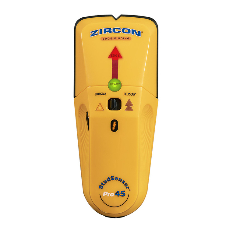
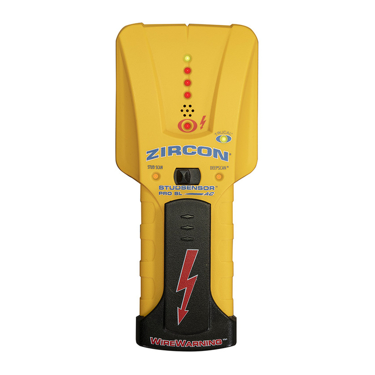
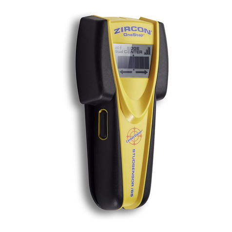
Popular Stud Sensor manuals by other brands

Sierra Monitor Corporation 4105 SERIES Applicability & effectivity manual

Sierra Monitor Corporation

Sierra Monitor Corporation 4105 SERIES Applicability & effectivity manual

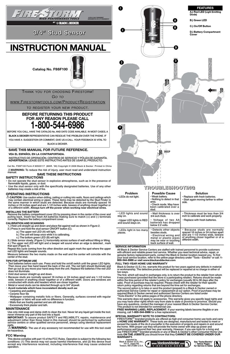
Black & Decker Fire Storm FSSF100 instruction manual

Black & Decker

Black & Decker Fire Storm FSSF100 instruction manual

PCE Instruments PCE-DPT1 manual

PCE Instruments

PCE Instruments PCE-DPT1 manual

Zircon StudSensor e30 manual

Zircon

Zircon StudSensor e30 manual

Precision Sensors Profinder 5000 Operating/safety instructions

Precision Sensors

Precision Sensors Profinder 5000 Operating/safety instructions

Stanley S150 user manual

Stanley

Stanley S150 user manual

BLACK DECKER SF100 instruction manual

BLACK DECKER

BLACK DECKER SF100 instruction manual

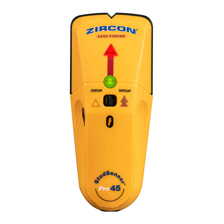
Zircon StudSensor Pro manual

Zircon

Zircon StudSensor Pro manual

manuals.online logo
manuals.online logoBrands
  • About & Mission
  • Contact us
  • Privacy Policy
  • Terms and Conditions

Copyright 2025 Manuals.Online. All Rights Reserved.