Trenton Systems HDEC Series User manual

THS2085
HDEC®Series
2U RACKMOUNT
COMPUTER
No. THS2085-xxx Revision A
INSTALLATION GUIDE
Publication No. 8402085-03396

WARRANTY
The following is an abbreviated version of Trenton Systems’ warranty policy for rackmount computer
products. For a complete warranty statement, contact Trenton or visit our website at
http://www.trentonsystems.com/.
All boards used in systems delivered by Trenton are covered under a pass-through warranty. For example,
if Trenton HDEC Series boards are used in the system then these boards will carry a five-year warranty.
All other system sub-components including but not limited to power supplies, DVDs, CD-ROMS, etc. are
covered under their original manufacturer’s warranty. All systems built by Trenton are warranted against
defects in material, workmanship and design for a period of one year from date of delivery. Repair or
replacement products will be warranted for a period of three months from the date of shipment or for the
remainder of the original warranty period for that particular product, whichever is longer. Any software or
firmware that is delivered by Trenton will be warranted for a period of one year to perform in accordance
with published specifications prepared, approved and issued by Trenton and/or the appropriate 3rd party
vendor. Contact Trenton for the complete system warranty policy.
Buyer agrees that if a Trenton product proves defective, Trenton is only obligated to repair, replace or
refund the purchase price of this product at Trenton's discretion. The warranty is void if the product has
been subjected to alteration, neglect, misuse, or abuse; if any repairs have been attempted by anyone other
than Trenton; or if failure is caused by accident, acts of God, or other causes beyond the control of Trenton.
Trenton reserves the right to make changes or improvements in any product without incurring any
obligation to similarly alter products previously purchased.
In no event shall Trenton Systems, Inc. be liable for any defect in hardware or software or loss or
inadequacy of data of any kind, or for any direct, indirect, incidental or consequential damages arising out
of or in connection with the performance or use of the product or information provided. Trenton Systems,
Inc.’s liability shall in no event exceed the purchase price of the product purchased hereunder. The
foregoing limitation of liability shall be equally applicable to any service provided by Trenton Systems,
Inc.
RETURN POLICY
Products returned for repair must be accompanied by a Return Material Authorization (RMA) number,
obtained from Trenton Systems prior to return. Freight on all returned items must be prepaid by the
customer, and the customer is responsible for any loss or damage caused by common carrier in
transit. Items will be returned from Trenton Systems via Ground, unless prior arrangements are made by
the customer for an alternative shipping method
To obtain an RMA number, call us at (800) 875-6031 or (770) 287-3100. We will need the following
information:
Return company address and contact
Model name
Serial number from chassis label
Description of the failure
An RMA number will be issued. Mark the RMA number clearly on the outside of each box, include a
failure report for each item and return the product(s) to our Lawrenceville, GA facility:
TRENTON Systems, Inc.
1725 MacLeod Drive
Lawrenceville, GA 30043
Attn: Repair Department
Contact Trenton for our complete service and repair policy.

TRADEMARKS
Trenton and Trenton Systems are trademarks or registered trademarks
of TRENTON Systems, Inc.
IBM, PC/AT, VGA, EGA, OS/2 and PS/2 are trademarks or registered trademarks
of International Business Machines Corp.
Intel is a registered trademark of Intel Corporation.
MS-DOS and Microsoft are registered trademarks of Microsoft Corp.
All other brand and product names may be trademarks or registered trademarks
of their respective companies.
LIABILITY DISCLAIMERS
In no event will Trenton Systems be responsible or liable for indirect or consequential damages resulting
from the use or application of this equipment.
The examples and diagrams in this manual are included solely for illustrative purposes. Because of the
many system variables and application requirements associated with any particular installation, Trenton
Systems cannot assume responsibility or liability for actual system use based on the examples and
diagrams. No patent liability is assumed by Trenton Systems with respect to the use of the information,
components, equipment or software described in this manual. This manual is as complete and factual as
possible at the time of publication; however, the information in this manual may have been updated since
that time. Trenton Systems, Inc. reserves the right to change the functions, features or specifications of
their products at any time, without notice.
Reproduction of the contents of this manual, in whole or part, without written permission of Trenton
Systems is prohibited.
Copyright ©2016 by Trenton Systems, Inc. All rights reserved.
E-mail: Support@TrentonSystems.com
Web: www.TrentonSystems.com
TRENTON Systems, Inc.
1725 MacLeod Drive • Lawrenceville, Georgia 30043
Sales: (800) 875-6031 • Phone: (770) 287-3100 • Fax: (770) 287-3150

THS2085 Installation Guide
Trenton Systems, Inc.
Table of Contents
HANDLING PRECAUTIONS I
BEFORE YOU BEGIN II
INTRODUCTION II
EXTERNAL POWER SOURCE II
INTERNAL 5V CURRENT LIMIT II
CHASSIS RACK MOUNTING II
CHAPTER 1 - SYSTEM OVERVIEW 1-1
DESCRIPTION 1-1
BACKPLANE,SHB &SYSTEM POWER SUPPLY MODELS 1-1
ADDITIONAL SYSTEM ELEMENTS 1-2
SHB BATTERY 1-2
PACKING LIST 1-2
CHAPTER 2 - SYSTEM DIMENSIONS & LAYOUT 2-1
SYSTEM DIMENSIONS 2-1
CHAPTER 3 - INSTALLATION INSTRUCTIONS 3-1
ENVIRONMENTAL CONSIDERATIONS 3-1
RACK MOUNTING 3-1
RACKMOUNT INSTRUCTIONS 3-1
SLIDE RAIL INSTALLATION 3-1
CONNECTING AC POWER 3-5
CHAPTER 4 - REPLACING SYSTEM COMPONENTS 4-1
OPENING THE THS2085 4-1
REPLACING COMPONENTS 4-1
COOLING FANS 4-1
STORAGE DRIVES 4-1
AIR FILTER 4-2
POWER SUPPLY -REDUNDANT 4-2
PREPARATION FOR SHIPMENT 4-2
CHAPTER 5 - CHASSIS SPECIFICATIONS 5-1
ENVIRONMENTAL 5-1
ELECTRICAL 5-1
PHYSICAL 5-1
AGENCY APPROVALS 5-1
CHAPTER 6 - CERTIFICATION DOCUMENTS 6-1

THS2085 Installation Guide
i Trenton Systems, Inc.
Handling Precautions
WARNING: This system has internal components which may be damaged by electrostatic discharge.
To protect internal components from electrostatic damage, be sure to observe the following precautions
when handling or storing the system:
• The THS2085 has a net chassis weight of approximately 23.8lbs. (10.8kg). This base chassis
weight includes the chassis, a system host board, a 2U butterfly format backplane and a rear-
mounted, 1U removable power supply. Use proper lifting techniques when moving and installing
the system.
• When removing or installing boards and sub-components, keep these components in their static-
shielded bag and/or packaging until you are ready to for component installation.
• Handle the sub-components by their edges.
• Do not touch any sub-component I/O connector pins. Do not apply pressure or attach labels to the
board-level sub-components.
• Use a grounded wrist strap at your system or ground yourself frequently by touching the metal
chassis of the system before handling any sub-components.
• Ensure the systems external power source has a solid connection to an earth ground.
• Use antistatic padding on all work surfaces when installing or removing sub-components.
• Avoid static-inducing carpeted areas.

THS2085 Installation Guide
Trenton Systems, Inc. ii
Before You Begin
INTRODUCTION
It is important to be aware of the information listed below before installing your Trenton rackmount
computer. System performance may be affected by incorrect usage of these features.
EXTERNAL POWER SOURCE
Incoming AC power must be supplied to each receptacle located at the rear of the chassis. This AC power
receptacle must be connected to a power source with a solid earth ground, and capable of delivering 110-
240VAC at 50 to 60Hz. The typical maximum current draw of the rackmount computer is 4.07A per
incoming power receptacle.
INTERNAL 5V CURRENT LIMIT
The maximum current limits for the +5V, +3.3V and +12V outputs from the system power supply are 32A,
32A and 65A respectively. The system’s power monitoring circuits will shut the system down if these
maximum current limits are drawn from the power supply.
CHASSIS AIRFLOW
When installing the chassis, ensure that a minimum free air space is available around the system. The
installation should have a minimum of 4-6 inches (101-152mm) behind the chassis and 7-8 inches
(178-203mm) in front of the chassis. Any front cabinet doors or access aisles must accommodate a
THS2085 front chassis clearance of at least 7.0” (178mm) in order to provide proper clearance for the
chassis’ front door, front panel I/O port connections and to gain access to the system air filter for
maintenance. Ideally, a chassis clearance of 0.5-1.5 inches (13-38mm) above the system is desirable, but
not required.
CHASSIS RACK MOUNTING
The THS2085 system can be installed in a rackmount cabinet that conforms to EIA standards for computer
equipment with 19-inch wide panels. The cabinet must be tall enough to accommodate the computer’s
height and deep enough to accommodate the system’s depth, while providing the proper clearances for air
flow and cabling. A cabinet with a standard depth of 31.5 inches (800mm) will provide the suggested
minimum rear chassis clearances needed for an installation.
THS2085 Installation Guide
1-1 Trenton Systems, Inc.
Chapter1-System Overview
DESCRIPTION
The Trenton THS2085-xxx is a CE-compliant and UL listed*, 2U rackmount computer chassis that offers
choices in HDD and media drive bay configurations with system support for the HDB8227, 2U butterfly
format backplane, an HDEC Series system host board such as the HEP8225, and a system power supply.
The THS2085 rackmount chassis supports two 3.5” HDD bays that are capable of supporting up to four 2.5”
hot swap HDD/SDD storage drives, a Slim-Line optical media bay, a single 860W system supply, or an up to
800W redundant supply, and a front access air filter. These components maximize power delivery and
cooling to ensure long-life system reliability with minimal Mean-Time-To-Repair (MTTR) times.
*Refer to the agency approval section in chapter five and the THS2085 Certificate Of Compliance document in chapter six for a
complete listing of the Council Directive: 2004/108/EC-EMC Directive standards to which conformity is declared.
BACKPLANE,SHB &SYSTEM POWER SUPPLY MODELS
NOTE: The chart below illustrates backplanes, SHBs and system power supplies supported in the Trenton
THS2085-xxx system. The three characters to the right on the hyphen indicate the specific backplane, SHB
and power supply combination.
System Model
Number
Backplane
Model
SHB Model
Number
Description of Backplane, SHB and System Power Supply
Combination
THS2085-000
HDB8227
HEP8225
Backplane: 1 SHB Slot, and 4 x16 PCIe option card slots
SHB: Dual-processor HDEC Series HEP8225 System Host Board
(part no. 92-822561800000) with two Intel®Xeon®E5-2680 v3 processors,
four 8GB DDR4-2133, and four 16GB DDR4-2133 DIMMs installed
System Power Supply: 2U 600W, rear-mount, redundant
See the HEP8225 web page for more SHB details
See the HDB8227 web page for more backplane details
THS2085-001
(CE, UL and
FCC Part 15,
Subpart B
compliant
configuration)
HDB8227
HEP8225
Backplane: 1 SHB Slot, and 4 x16 PCIe option card slots
SHB: Dual-processor HDEC Series HEP8225 System Host Board
(part no. 92-822561800000) with two Intel®Xeon®E5-2680 v3 processors,
four 8GB DDR4-2133, and four 16GB DDR4-2133 DIMMs installed
System Power Supply: 2U 650W, single-fixed mount power supply
See the HEP8225 web page for more SHB details
See the HDB8227 web page for more backplane details
THS2085-002
HDB8227
HEP8225
Backplane: 1 SHB Slot, and 4 x16 PCIe option card slots
SHB: Dual-processor HDEC Series HEP8225 System Host Board
(part no. 92-822561800000) with two Intel®Xeon®E5-2680 v3 processors,
four 8GB DDR4-2133, and four 16GB DDR4-2133 DIMMs installed
System Power Supply: 1U 500W, removable power supply
See the HEP8225 web page for more SHB details
See the HDB8227 web page for more backplane details

THS2085 Installation Guide
Trenton Systems, Inc. 1-2
ADDITIONAL SYSTEM ELEMENTS
Each THS2085-xxx configuration contains the following active components:
4 –SATAIII, 2.5” HDD, 500GB, with two each installed in two front access/hot swap drive carriers
1 –Slim-Line R/W DVD
4 –67CFM system fans
Consult with Trenton for available storage drives and optical media drives compatible with the THS2085.
SHB BATTERY
CAUTION: Risk of explosion if the system host board battery is replaced by an incorrect type. Dispose of
used batteries according to the instructions.
PACKING LIST
The CE-compliant and UL listed system is shipped with the following:
• THS2085 2U rackmount computer
• One or Two, 10ft. (3.1m) AC power cords

THS2085 Installation Guide
2-1 Trenton Systems, Inc.
Chapter2-System Dimensions & Layout
SYSTEM DIMENSIONS
Note: Ensure that
there is at least 4-6
inches (101-152mm)
behind the chassis and
7-8 inches
(178-203mm) in front
of the chassis of open
space in order to
allow for cable
connections, airflow,
and front door
mechanical clearance.
PCI Express option card slot locations
THS2085-001 Rear View (2U Fixed-mount Power Supply Configuration)
Front View
THS2085-002 Rear View (1U Removable Power Supply Configuration)
19.0”
(48.3cm)
SHB Slot
17.0”
(43.2cm)
3.5”
(8.9cm)
18.2”
(46.2cm)
THS2085-002 Inside View (SHB heat sinks and fans installed) Side View
Disk Drives
&
Media Bay
1U
Removable
Power
Supply
HDB8227
Butterfly
Backplane
HEP8225 SHB
(low profile cooling
solution installed)
3.5”
(8.9cm)
THS2085-000 Rear View (2U Redundant Power Supply Configuration)


THS2085 Installation Guide
3-1 Trenton Systems, Inc.
Chapter3-Installation Instructions
ENVIRONMENTAL CONSIDERATIONS
When installing the chassis, ensure that a minimum free air space is available around the system. The
installation should have a minimum 4-6 inches (101-152mm) of clearance behind the chassis and 7-8
inches (178-203mm) in front of the chassis. Ideally, a chassis clearance of 0.5-1.5 inches (13-38mm)
above the system is desirable, but not required. The computer is equipped with fans to help ensure proper
cooling.
RACK MOUNTING
The THS2085 system can be installed in a rackmount cabinet that conforms to EIA standards for computer
equipment with 19-inch wide panels. The cabinet must be tall enough to accommodate the computer’s
height and deep enough to accommodate the system’s depth, while providing the proper clearances for air
flow and cabling. A cabinet with a standard depth of 31.5 inches (800mm) should be sufficient.
The THS2085 is designed to be supported in the cabinet with rack slides or placed on a cabinet shelf. The
front flanges of the computer are designed to secure the THS2085 to the rack cabinet’s front mounting rails
RACKMOUNT INSTRUCTIONS
A) Elevated Operating Ambient - If installed in a closed or multi-unit rack assembly, the operating ambient
temperature of the rack environment may be greater than room ambient. Therefore, consideration should be
given to installing the equipment in an environment compatible with the maximum ambient temperature
(Tma) specified by the manufacturer.
B) Reduced Air Flow - Installation of the equipment in a rack should be such that the amount of air flow
required for safe operation of the equipment is not compromised.
C) Mechanical Loading - Mounting of the equipment in the rack should be such that a hazardous condition
is not achieved due to uneven mechanical loading.
D) Circuit Overloading - Consideration should be given to the connection of the equipment to the supply
circuit and the effect that overloading of the circuits might have on over current protection and supply
wiring. Appropriate consideration of equipment nameplate ratings should be used when addressing this
concern.
E) Reliable Earthing - Reliable earthing of rack-mounted equipment should be maintained. Particular
attention should be given to supply connections other than direct connections to the branch circuit (e.g. use
of power strips).
F) Chassis Access –Use in a RESTRICTED ACCESS LOCATION only.
NOTE: Only trained personnel shall install or operate this equipment

THS2085 Installation Guide
Trenton Systems, Inc. 3-2
SLIDE RAIL INSTALLATION
Trenton offers slide rail kits to help with the installation of a 2U Trenton Systems’ computer chassis. The
depth of your component rack will determine the best slide rail kit for you application. For example, when
using a typical 31.5”/800mm-deep component rack Trenton’s 24-30” slide rail kit (part no. 198500001016) is
the best choice. The 18-24” slide rail kit (part no. 198500001066) would be the best choice for component rack
with a smaller chassis depth dimension. The installation instructions are the same regardless of which
Trenton slide rail kit is selected. Note: The quantity of mounting hardware pieces may vary based on the
specific slide rail kit length selected.
1. Remove slide rails from the box along with the rail frames, optional rack frame mounting brackets
and the mounting hardware. The Trenton 18” slide rail kit includes the following items.
2, 18” slide rails
4, rail frames
4, rack frame mounting brackets (optional)
1, mounting hardware bag number S-047-0 includes:
10 mounting rail to computer chassis screws
1, mounting hardware bag number S-017-1 includes
36 rail frame to 19” rack mounting screws
10 nuts
10 flat washer
2. Take one of the slide rails and slide the inside portion of the rail completely out until you hear an
audible click.
3. On the inside of the rail, you will see a rail stop hook, push the hook up to release and detach the
inside portion of the slide completely from the outside portion of the rack slide.
4. Set aside this inside portion of the rack slide. You will be mounting this part of the rack slide to a
side of the computer chassis later in this procedure.
5. Repeat steps 3 and 4 for the other rack slide. (Refer to figure 1 as necessary)
6. Using four mounting screws from hardware bag S-047-0, attach an inside rail to the left side of the
computer chassis as shown in figure 2. Note –the rubber bumper on the inside rail slide needs to
be facing toward the front of the computer and the cut-out portion of the rail release latch should
be pointing downward indicating that the slide rail has been properly mounted to the correct side
of the computer chassis.
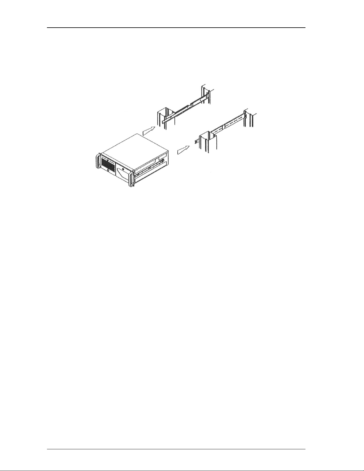
Figure 1 –Rail Stop Hook Detail
Figure 2 –Inside Rail Mounting Detail

THS2085 Installation Guide
3-3 Trenton Systems, Inc.
7. Repeat step 6 for the right side on the computer and refer to figure 2 as necessary.
8. Standard 19” instrument racks have a wide variety of mounting hole types. Some mounting holes
are threaded, but most of not, some mounting holes are located on side flanges rather than the
front and back of the rack supports and finally some holes are round while others are rectangular.
The following steps assume that your 19” instrument rack has round, non-threaded mounting holes
for the slide rail frames. The optional rack frame mounting brackets accommodate the side flange
rackmount hole placements. If your rack has other mounting hole types or placements, then you
may need to consult with your rack supplier to obtain the correct slide rail mounting hardware.
9. The rubber bumper on the outside portion of slide rails are to be located toward the rear of the
19”rack.
10. Refer to figure 3 and attach two rail frames each to the outside portion of both rack slides using
the hardware in bag number S-107-1.
11. If the mounting holes are on the inside portions of your rackmount supports, then mount each
assembly directly to the rack supports as shown in figure 4-A.
12. If the mounting holes are located on side flanges then you will need to use the optional rack frame
mounting brackets.
13. Attach the optional brackets to the rack slides as shown in figure 4-B and attach the completed
assembly to the rack supports.
14. You will need to supply the hardware necessary to mount your completed rail and frame
assemblies to the rackmount enclosure supports.
Figure 3 –Outside Rail and Frame Assembly
Figure 4A –Rail/Frame Mounting –Inside
Rackmount Hole Locations
Figure 4B –Rail/Frame Mounting –Side Flange
Rackmount Hole Locations
THS2085 Installation Guide
Trenton Systems, Inc. 3-4
15. CAUTION –Ensure that when mounting the completed rail and frame assemblies to the 19” rack
that the left and right assemblies are the same distance from the top or bottom of the rack. Failure
to align the slide rails properly will result in the computer not being level inside the rack. If the
slides are grossly misaligned then you may not be able to slide the chassis into the slide rails.
16. Refer to figure 5 and slide the chassis into the rails attached to the frame of the rackmount
enclosure. (You should have another person help you lift and slide the chassis into the enclosure.)
17. You should hear and audible “click” when the rail stop hooks on the slide engage with the chassis
stops inside the rails mounted to the enclosure supports.
18. Push up on the rail stop hooks and push the chassis completely into the enclosure.
19. Each Trenton System chassis has two through holes on each chassis-mounting flange. Use these
holes to secure your chassis to the enclosure. (Note: The hardware used in this step is highly
dependent on your enclosure type; therefore, Trenton does not provide the hardware for this step.)
20. Contact Trenton Systems if you require additional assistance.
Figure 5 –Chassis Installation
THS2085 Installation Guide
3-5 Trenton Systems, Inc.
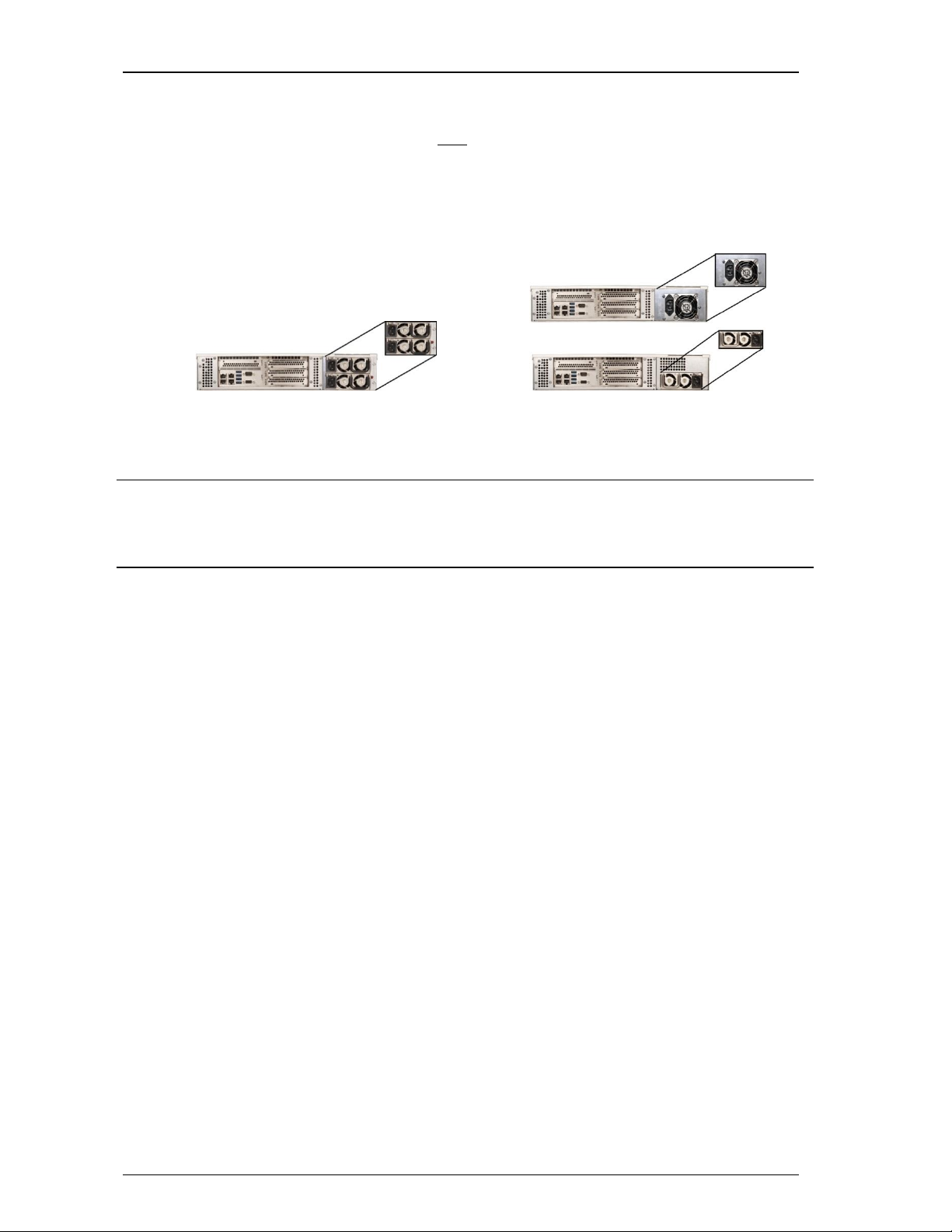
CONNECTING AC POWER
When using the THS2085 with the redundant power supply option, a single-phase power source providing
110-240VAC at 50 to 60Hz must be connected to each AC input power outlet located at the rear of the
chassis. The fixed-mount version of the THS2085 just has one AC input power outlet to connected to the
single-phase power source. Power must be available at all available three-pin AC input receptacles located
at the rear of the system. An over-current protection device shall protect each power cord.
To connect AC power to the computer:
1. Establish a chassis to earth ground connection to the THS2085 chassis.
2. Connect the AC power cords to all available AC receptacles.
3. Connect the plug end of the power cords into the main outlets.
NOTE: The maximum current limits for the +5V, +3.3V and +12V outputs from the system power supply
are 32A, 32A and 65A respectively. The system’s power monitoring circuits will shut the system down if
these maximum current limits are drawn from the power supply.
THS2085-000 with Redundant Power Supply THS2085-001/002 with Fixed-mount Power Supply


THS2085 Installation Guide
4-1 Trenton Systems, Inc.
Chapter4-Replacing System Components
OPENING THE THS2085
A trained electronics technician may need to remove the top cover of the THS2085 to install or remove the
option cards.
NOTE: When installing option cards into the THS2085 rackmount computer you must ensure that the card
installation does not result in non-conformance to the safety or EMC requirements for this product.
To open the computer:
1. Disconnect both AC power cords
2. Remove the twelve (12) screws attaching the cover to the chassis. There are three screws on the
right and left-side of the chassis, three screws on the back-front and three screws on the top-front
securing the cover to the chassis
3. Slide the cover back slightly and lift it off the chassis
4. Ensure you are properly grounded before installing or removing option cards
5. Remove the option card hold down bar to install or remove cards
NOTE: NEVER install or remove any option card from a backplane if any +5V AUX / Standby LED
is ON.
REPLACING COMPONENTS
The system fans and storage drives for the THS2085 are designed for easy access. Make sure you have a
front chassis clearance of at least 6” (152mm) to remove or install system cards.
COOLING FANS
The four 60mm cooling fans of the THS2085 are attached to a four-fan carrier assembly that is mounted to
front face of the main chassis just behind the front access door. The fan carrier assembly is secured to the
chassis front with quick release levers. Flip open each lever and pull the fan carrier assembly straight out
to remove. You may either replace all four fans at once with a new fan carrier assembly, or replace
individual fans as necessary. A connector on the fan carrier assembly connects each fan to the chassis’
+12V supply line.
STORAGE DRIVES
The storage drives of the THS2085 are mounted in lockable drive carriers that are accessible behind the
systems front door. Unlock a drive carrier to start the drive removable process. Drive carrier mounted
HDDs are secured to the chassis with either a black slide catch. Slide the black HDD catch to the left to
grasp the drive carrier handle and then pull out the carrier to remove. Once the carrier is removed, you may
mount or remove the drive or drives as necessary. Reverse the procedure to re-install a drive carrier. Don’t
forget to re-lock the carrier when finished.
THS2085 Installation Guide
Trenton Systems, Inc. 4-2
AIR FILTER
As the system ages and depending on the installation you may need to periodically clean or replace the
system’s air filter. The filter cleaning/replacement frequency is highly dependent on the installation
environment, but should be done at least once a year. Loosen the thumbscrews on systems front door to
remove the filter located inside the door for cleaning or replacement.
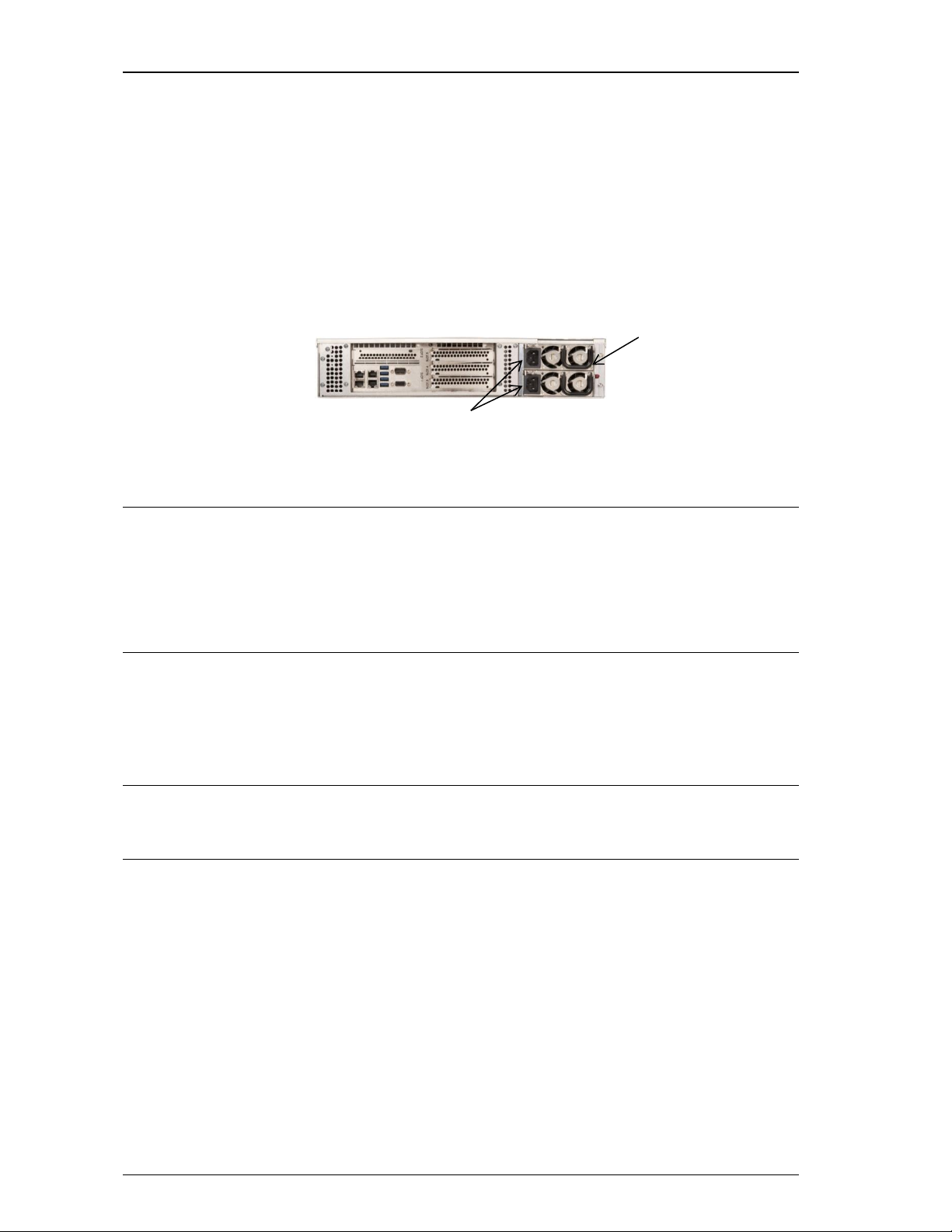
POWER SUPPLY -REDUNDANT
The 2U 600W redundant power supply used in the THS2085 rackmount computer is mounted in the rear of
the system as shown in the figure below.
The system’s redundant power supplies should only be removed and replaced by a trained electronics
technician.
NOTE: The maximum current limits for the +5V, +3.3V and +12V outputs from the system power supply
are 32A, 32A and 65A respectively. The system’s power monitoring circuits will shut the system down if
these maximum current limits are drawn from the power supply.
CAUTION: Risk of explosion if the system host board battery is replaced by and incorrect type. Dispose
of used batteries according to the instructions.
PREPARATION FOR SHIPMENT
The THS2085 should always be removed from the rack cabinet if the unit must be shipped to another site.
If possible, use the original shipping carton to ship the THS2085.
NOTE: Never ship the THS2085 when it is mounted inside a rack; damage to the computer and rack
cabinet will likely result.
Reverse the installation steps in chapter three to remove the THS2085 from the rack cabinet. Do not forget
to remove the chassis’ earth ground wire before attempting computer removal.
Redundant power supply
Incoming power connections

THS2085 Installation Guide
5-1 Trenton Systems, Inc.
Chapter5-Chassis Specifications
ENVIRONMENTAL
Temperature
Operating
5C to 35C typical
Storage
-20C to 70C
Cold Excursion Temp
-40C for up to sixteen hours
Relative Humidity
5% to 90%, non-condensing
Specific operating temperature ranges for the THS2085 are dependent on the number of option cards and
other system components installed. Extended operating temperature CPUs resulting in a system’s
achievable operating temperature range higher than what is stated here may be available for use on the
system host inside the THS2085. The reverse can also be true in that a system subcomponent could have a
lower operating temperature range that could lower the system’s overall operating temperature range.
Contact Trenton for more details.
ELECTRICAL
Line Voltage
110-240VAC
Line Frequency
50-60Hz
Power Consumption
450W typical, 650W max.
PHYSICAL
Approximate Dimensions
(W x H x D)
19” x 3.5” x 18.2”
48.3cm x 8.9cm x 46.2cm
Net Weight
23.8 lbs. (10.8 kg) (includes chassis, SHB, backplane, and 1U removable PS)
AGENCY APPROVALS
UL
(THS2085-001 system configuration)
UL listed product listed in file #E208896-A6-UL dated
2016-07-26
Environmental
(THS2085-001 system configuration)
IEC 60721-3-3:2002 including Class 3K3, 3Z3, 3Z4,
3M4 and 3S2
IEC 60721-3-2:1997 including Class IE23 and 2M3
CE –Application of Council Directive:
89/336/EEC - EMC Directive
(THS2085-001 system configuration)
IEC 55022: 2008 Class A, IEC 61000-3-2:2014 , IEC
61000-3-3: 2013, IEC 61000-4-2: 2008, IEC 61000-4-
3: 2006 + A1: 2007 + A2: 2010, IEC 61000-4-4: 2012,
IEC 61000-4-5: 2014, IEC 61000-4-6: 2013, IEC
61000-4-8: 2009 & IEC 61000-4-11: 2004
FCC Class B, Subpart 15
(THS2085-001 system configuration)
EN 55032: 2015 guidelines for Radiated & Conducted
Emissions

This manual suits for next models
1
Table of contents
Other Trenton Systems Desktop manuals


